manuals.online logo
Brands
  1. Home
  2. •
  3. Brands
  4. •
  5. ideal commercial
  6. •
  7. Boiler
  8. •
  9. ideal commercial IMAX XTRA E320 User manual

ideal commercial IMAX XTRA E320 User manual

USER GUIDE
IMAX XTRA
E320 E400 E480 E560
June 2018
UIN 211216 A04
When replacing any part on this appliance, use only spare parts that you can be assured conform to the safety and performance
specification that we require. Do not use reconditioned or copy parts that have not been clearly authorised by Ideal.
For the very latest copy of literature for specification and maintenance practices visit our website www.idealcommercialboilers.com
where you can download the relevant information in PDF format.
CAUTION.
To avoid the possibility of injury during the installation, servicing or cleaning of
this appliance care should be taken when handling edges of sheet steel components.
All Gas Safe Registered Engineers carry a Gas Safe Register ID card, and have a registration number. Both should
be recorded in your Log Book. You can check your installer by calling Gas Safe Register direct on 0800 4085500
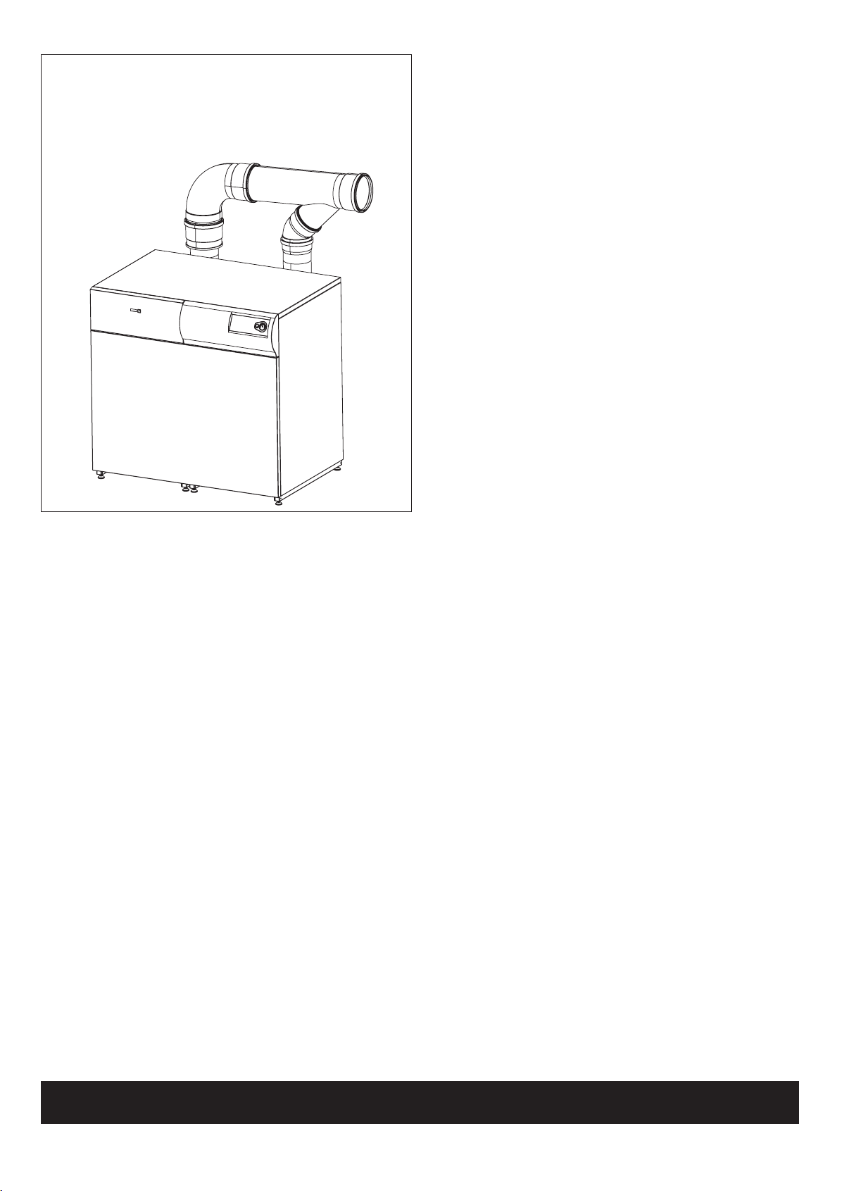
Introduction
The IMAX XTRA E boilers are fully automatically controlled, oor
standing, fanned, super efcient condensing appliances.
Due to the very high efciency, condensate is produced from the
ue gases and this is drained to a suitable disposal point through
the plastic waste pipe at the bottom of the boiler. A condensate
'plume' will also often be visible at the ue terminal.
Safety
Current Gas Safety (Installation & Use)
Regulations or rules in force.
In your own interest, and that of safety, it is the law that this boiler
must be installed and maintained by a Gas Safe Registered
Engineer or in IE a competent person, in accordance with the
above regulations.
The appliance should be serviced at least once a year by a Gas
Safe Registered Engineer or in IE a competent person.
It is essential that the instructions in this booklet are strictly
followed, for safe and economical operation of the boiler.
Electricity Supply
The appliance must be earthed.
Supply 230 V - 50 Hz. The fusing should be 7A for E320-E560.
This appliance is intended to be connected to the supply via two
double-pole switches, having a 3mm contact separation in both
poles, serving only the boiler and system controls. Alternatively,
two 3-pin UNSWITCHED sockets may be used.
Important Notes
• This appliance must not be operated without
the casing correctly tted.
• Do not store objects around or on the boiler, and keep access
clear at all times.
• Do not obstruct ventilation ducts, grilles or openings in the
boiler room, room space or compartment that the appliance is
installed in, or the passage of combustion and ventilation to
the boiler.
• Do not turn off the boiler if it is to be left unattended in frosty
weather.
• If it is known or suspected that a fault exists on the boiler then
it MUST NOT BE USED until the fault has been corrected by a
Gas Safe Registered Engineer or in IE a competent person.
• Flammable materials must not be placed in close proximity to
the appliance. Materials giving off ammable vapours must not
be stored in the same room as the appliance.
In cases of repeated or continuous shutdown a Gas Safe
Registered Engineer or in IE a competent person should be called
to investigate and rectify the condition causing this and carry out
an operational test after each intervention on the device. Only the
manufacturers original parts should be used for replacement.
Minimum Clearances
Rear:
1000mm or adequate space from the rear of the jacket to make
the ue connections and access to the ue sample point, drain
connection, ue and any safety or control devices.
Left Side:
450mm.
Right Side:
450mm.
Front:
600mm; except, access doors may be closer, but not less than
200mm and 600mm must still be available for service across the
width of the boiler.
Top:
500mm.
To light the boiler (Refer to Frame 1)
1. CHECK THAT THE ELECTRICITY SUPPLY TO THE BOILER
IS OFF.
2. Set the burner on/off switch (A) to off.
3. Switch on the electricity supply to the boiler and check that all
external controls, e.g. programmer, room thermostat etc. are
on. Allow the boiler to carry out a self check.
4. Set the burner on/off switch (A) to ON.
The boiler will commence the ignition sequence, supplying heat to
the system when required.
IMAX XTRA E
Natural Gas only
Destination Countries: GB, IE
2
0
I
xtra
MODE STEP STORE
RESET
+
A BC D
EF G H I
im8219
MASTER MODULE
CONTROL PANEL
1
BOILER CONTROLS / DISPLAY (MASTER PANEL SHOWN)
In normal operation the display (C) shows the boiler status (see
table above) and the water system ow temperature.
Blocking Mode
The boiler will enter blocking mode under certain fault
conditions. Whilst in blocking mode the burner is switched off.
Once the fault conditions are clear the boiler will automatically
reset itself. In blocking mode the display will alternate between
showing a '9' in digit one, along with the ow temperature in
digits 2, 3 and 4, e.g.
Followed by the blocking code 'bxx', e.g.
Error Mode
In error mode the display will ash on and off with the error code
shown, e.g.
The boiler will enter error mode under certain fault conditions.
9 9 6
b 1 8
The unit will be inoperative until the fault is rectied. The reset
button is used to reset the boiler control module after an error
has occurred.
Self Check and Anti-Seize Modes
After switching on the mains power or after a reset, the boiler
performs a selfcheck, i.e. the DHW valve (if connected) is
energised rst for 15 seconds then the CH pump is switched on
for a further 10 seconds. This cycle repeats itself every 24hrs,
as long as no heat request is given in 24hrs.
Burner on/off Switch
With the burner switch set to 'off' the boiler will not respond to a
CH demand. However, it will respond to a DHW demand and the
pump anti-seize and frost protection modes are still operational
any one of which could cause the boiler to re. Note. The burner
switch is NOT a mains isolation switch.
CH/DHW Systems
In standby mode pressing and holding the '+' button for 3
seconds turns the CH system on/off.
In standby mode pressing and holding the '-' button for 3
seconds turns the DHW system on/off.
E 3 6
3
RESET
C D
SLAVE MODULE
CONTROL PANEL
Sequence Boiler Status
A DHW valve energised
0 Standby, no heat request
1 Pre-purge, post purge
2 Ignition
3 Burner on in CH mode
4 Burner on in DHW mode
5 Waiting for air pressure switch to open or close
6 Burner off because a set value has been reached
7 Pump overrun in CH mode
8 Pump overrun in DHW mode
Operation
LEGEND
A. Burner switch
B. Pressure gauge
C. Display
D. Reset button
E. Mode button
F. Step button
G. Store button
H. + button (to increase values)
I. - button (to decrease values)
To shut Down the Boiler
1. For short periods
Set the external controls to OFF. Wait 10 minutes and then
isolate the mains supply to the boiler.
2. For longer periods
Set the external controls to OFF. Wait 10 minutes and then
isolate the mains supply to the boiler. For longer periods the
entire system should be drained, including the domestic hot
water supply.
To Relight the Boiler
Rell the system if it has been drained, taking care to ensure no
air is in the boiler or system.
Repeat the procedure detailed in 'To light the boiler'.
Frost Protection
The IMAX XTRA oiler has built into its control system the facility
to protect the boiler only against freezing.
Note.
This may not protect remote parts of the system, in which case
a separate frost protection should be tted.
Boiler Overheat
Boiler overheating is detected by electrical sensors connected
to the boiler control module. If the boiler overheats it will shut
down and the display will show E18. Press the 'reset' button
(D) and the boiler will relight. If the fault recurs turn off the
boiler and consult a Gas Safe Registered Engineer or in IE a
competent person.
Condensate Drain
The condensate drain must not be modied or blocked.
Blockage of the condensate drain, caused by debris or freezing,
can cause automatic shutdown of the boiler or leakage from the
condensate trap mounted on the bottom of the boiler.
If freezing is suspected and the pipe run is accessible an attempt
may be made to free the obstruction by pouring hot water over
the exposed pipe and clearing any blockage from the end of the
pipe. If this fails to remedy the problem the assistance of a Gas
Safe Registered Engineer or in IE a competent person should be
sought.
Escape of Gas
Should a gas leak or fault be suspected contact your local gas
supplier without delay.
Do NOT search for gas leaks with a naked ame.
Cleaning
For normal cleaning simply dust with a dry cloth.
To remove stubborn marks and stains use a damp cloth and mild
detergent.
DO NOT use abrasive cleaning materials.
Ideal is a trademark of Ideal Boilers.
Registered Oce
Ideal Boilers Ltd., PO Box 103, National Avenue, Kingston Upon Hull, HU5 4JN
Tel 01482 492251 Fax 01482 448858
Registration No. London 322 137
I
deal Technical Helpline: 01482 498376
www.idealcommercialboilers.com
Ideal Boilers Ltd. pursues a policy of continuing improvement in the design and performance of its products.
The right is therefore reserved to vary specification without notice.

This manual suits for next models

3

Other ideal commercial Boiler manuals

ideal commercial EVO S User manual

ideal commercial

ideal commercial EVO S User manual

ideal commercial Evomax 30 User manual

ideal commercial

ideal commercial Evomax 30 User manual

ideal commercial Evomax 40 User manual

ideal commercial

ideal commercial Evomax 40 User manual

ideal commercial Evomax 60 User manual

ideal commercial

ideal commercial Evomax 60 User manual

ideal commercial EVOMOD 250 User manual

ideal commercial

ideal commercial EVOMOD 250 User manual

ideal commercial HARRIER GTS 5 User manual

ideal commercial

ideal commercial HARRIER GTS 5 User manual

ideal commercial VICEROY GTS 8 User manual

ideal commercial

ideal commercial VICEROY GTS 8 User manual

Popular Boiler manuals by other brands

Viessmann Vitodens 200-W B2HA series Technical guide

Viessmann

Viessmann Vitodens 200-W B2HA series Technical guide

Baxi Eco5 Compact+ Operating and installation instructions

Baxi

Baxi Eco5 Compact+ Operating and installation instructions

Buderus Logano G234X user manual

Buderus

Buderus Logano G234X user manual

ACV delta pro rack Installation, operating and maintenance instructions

ACV

ACV delta pro rack Installation, operating and maintenance instructions

A.O. Smith Burkay HW-300 Installation & operation manual

A.O. Smith

A.O. Smith Burkay HW-300 Installation & operation manual

Alpha Alpha CombiMax 350 Installation guidelines

Alpha

Alpha Alpha CombiMax 350 Installation guidelines

Watts AERCO Benchmark Platinum 750 Reference manual

Watts

Watts AERCO Benchmark Platinum 750 Reference manual

Navien NCB-24LDWE User's information manual

Navien

Navien NCB-24LDWE User's information manual

Metal-Fach SLIM PELLET Technical and Operational Documentation

Metal-Fach

Metal-Fach SLIM PELLET Technical and Operational Documentation

Beretta C.S.I. installer and user manual

Beretta

Beretta C.S.I. installer and user manual

Instanta 1500 User instruction manual

Instanta

Instanta 1500 User instruction manual

Ferroli BLUEHELIX TECH S 45H manual

Ferroli

Ferroli BLUEHELIX TECH S 45H manual

Gorenje GBK 80 ORRN Instructions for use

Gorenje

Gorenje GBK 80 ORRN Instructions for use

Rima Heating Systems S.MAX Series Installation, operation & maintenance manual

Rima Heating Systems

Rima Heating Systems S.MAX Series Installation, operation & maintenance manual

Watts AERCO Benchmark OMM-0136 Operation and service manual

Watts

Watts AERCO Benchmark OMM-0136 Operation and service manual

Patterson-Kelley THERMIFIC MODU-FIRE Supplement

Patterson-Kelley

Patterson-Kelley THERMIFIC MODU-FIRE Supplement

Alarko ADK 200 Operation manual

Alarko

Alarko ADK 200 Operation manual

Potterton Gold H Range user guide

Potterton

Potterton Gold H Range user guide

manuals.online logo
manuals.online logoBrands
  • About & Mission
  • Contact us
  • Privacy Policy
  • Terms and Conditions

Copyright 2025 Manuals.Online. All Rights Reserved.