IDEAL Stripmaster 950 User manual

#45-950
#45-954
#45-950-1
Stripmaster
®Model 950™& Model 954
Wire Stripper

2
Table of Contents
Introduction..................................................................... 3
Warranty & Service Policy............................................... 3
Technical Data.................................................................
3
Unpacking....................................................................... 3
Operation
Hook-up Air............................................................... 4
Hook-up Air Regulator............................................... 4
Display ...................................................................... 4
Strip Length............................................................... 5
Service
Replacement Adjustment ........................................... 6
Replacement Guide.................................................... 7
Adjustments Clamp Stop ........................................... 7
Adjustments Partial Strip ........................................... 7
Circuit Board Adjustment........................................... 8
Stripmaster®Model 950™ & 950-1™
Alignment Adjustments.............................................. 9
Stripmaster®Model 954™
Adjustments............................................................... 10
Tips and Troubleshooting ............................................... 11
Ordering Blades and Wire Guides ................................... 12
Stripmaster®Model 950 & 954 Wire Stripper

3
Introduction
The IDEAL Stripmaster®Models 950™, 950-1 and 954 Wire Strippers are electrically operated, pneumatic precision production tools designed to strip a
variety of insulation types in the 10 to 30 AWG range.
Each unit is equipped to accommodate up to six different wire guide/blade and strip length configurations, allowing operators to strip multiple wire diame-
ters and insulations without switching tools or re-installing blade sets.
Consult the factory for standard guide and blade set availability. Special guides and blades are available upon request.
Warranty and Service Policy
Each unit is warranted to be free from defects in materials and workmanship under normal use and service for a period of 12 months after the date of
purchase. The obligations of IDEAL under this warranty shall be limited to repairing at the Sycamore, Illinois manufacturing facility any unit which
shall, within the 12 month period, be returned to use with the transportation charges prepaid, and with our examination shall disclosed to our satisfac-
tion to have been defective. This warranty shall not apply to any model which has been altered or repaired outside the factory in any way so as to affect
its operation nor which has been subject to misuse, negligence, accident or installed or operated in any other way than in accordance with our instruc-
tions, nor shall this warranty extend to repairs or replacement made necessary by the use of accessories not recommended by IDEAL.
Technical Data
Strip Lengths........................... Minimum: .125 inches (3mm)
Maximum: .63 inches (16mm)
Strip Capacity.......................... Minimum: #30 AWG (.05mm2)
Maximum: #10 AWG (6.0mm2)
Accuracy: ................................................. Meets Military specifications in most applications
Voltage:.................................................... 12 volts required for operation
120V/60Hz transformer supplied as standard
For 220V/50Hz application, order 45-951 transformer
Air Pressure: ............................................ 65 PSI max.
Air Filter:.................................................. Recommended, but not required
In-line Oiler:............................................. Not required
Blade Type: .............................................. Heat treated steel knife or die-type blades are available
Guide Bushings:....................................... Precision molded and machined Delrin
Strip Cycle: .............................................. Electronically adjustable strip and return speed
Dimensions:.................................. Width: 4-7/8 inches (124mm)
Depth: 10-1/2 inches (267mm)
Height: 5-1/4 inches (133mm)
Warranty:.................................................. 1-year limited warranty
Unpacking
Your IDEAL Stripmaster®Model 950™ and Stripmaster®Model 954 Wire Strippers have been factory preset and tested with the blades and wire guides
specified. Installation and hook-up of the unit to a CLEAN, DRY, REGULATED AIR SUPPLY IS REQUIRED FOR PROPER PERFORMANCE.
Models 950, 954 and 950-1 come equipped with a 12-volt adapter, air hose, IDEAL Mini T®Cutter (45-260), regulator mounting bracket, air regulator
kit and a set of hex key wrenches.
Description Cat. No.
Stripmaster®Model 950™ 45-950
Stripmaster®Model 954™ 45-954 (45-950 w/permanent face plate)
Special Stripmaster Model 45-950-1 45-950-1
Permanent Gripper Assembly (faceplate only) 45-950-4
Replacement Blades Consult Factory
Replacement Bushings Consult Factory
Air Regulator Kit 45-906
120V/60Hz Adapter K-7156
220V/50Hz Adapter 45-951
T®-Cutter Lite 45-260
Hex Key Set 691.02
Air Hose 45-807
Regulator Mounting Bracket LB-1135

Operation
Hook-up Electrical
Connect 12-volt supply to power jack located at the rear of the unit.
Plug wall mount transformer in standard 115V outlet (use 45-951 and
proper cord set for 220V service).
Hook-up Air
Connect 1/4” coiled air hose to the air inlet fitting located at the rear of the unit. This is a reusable compression type fitting.
Connect the air hose by inserting hose firmly into the compression fitting.
Hook-up Air Regulator
1. Attach regulator mounting
bracket to either side of the
unit, using two button-head
socket screws provided.
(#45-906)
2. Remove the retaining nut from the regulator body,
locate the regulator in the mounting bracket and
replace the retaining nut securely.
Thermal Head Rotation Speed
4
Connect the air line to a clean, dry,
regulated air supply.
Air pressure must be regulated to a
maximum 65 PSI.
To disconnect, simply depress the
red ring and pull on the air hose.
CAUTION: Do not attempt to
connect or disconnect the air
hose with compressed air in
the line.
1. Turn the power switch
to the ON position.
Green power indicator
light will illuminate.
2. Place the AUTO/SET-UP switch to the AUTO position.
Red indicator light will illuminate.
3. Actuate single-cycle switch to cycle the unit. This will show
unit is ready for operation.
Note: CYCLE IN PROGRESS
light will illuminate
during stripping cycle.
Display
With proper air and electrical connections, the unit is now ready for operation.
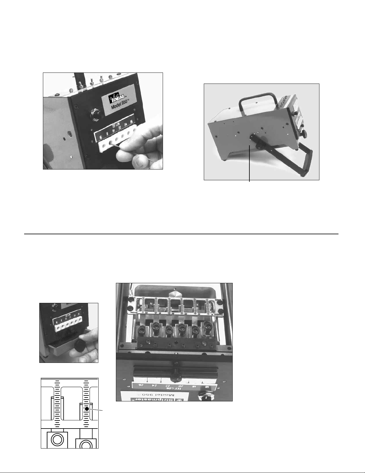
4. Observe the position of the trigger relative
to the indicating scale and loosen the
#8-32 socket head cap screw (use 5/32
hex wrench). Slide trigger to desired loca-
tion and retighten cap screw. Repeat this
procedure until all six triggers have been
set in their desired position.
Strip Length
Unit is equipped with six individual triggers. This allows
each wire port to be set-up to its own unique strip length.
1. Turn power switch to the OFF position. Leave air
supply connected.
2. Remove slug tray (Item 21)*.
3. Note position of wire port numbers 1 thru 6 from left to right with matching numbers
which correspond to the indicating scales on the contact plate (Item 19)*.
CONTACT PLATE (ITEM 19)*
TRIGGER ASSEMBLY (ITEM 16)*
8-32 CAP SCREW (ITEM 16)*
INDICATING SCALE 5. To check strip length, turn machine to its upright position and turn
power switch on. Strip several sample wires and verify proper strip
lengths. Repeat strip length adjustments as required.
CAUTION: Strip length range is 1/8” to 5/8”. Setting
strip length less than 1/8” may cause uncontrolled
cycling. Reset as required.
#2 #3
5
Operation (continued)
4. Insert the wire to be stripped into the wire guide hole until it engages the
trigger. Machine should cycle completely.
Note: Excessive force should not be required to
insert the wire into the proper wire guide.
CAUTION: The unit is designed to strip one wire per
cycle. DO NOT load multiple wires
simultaneously.
The unit is designed to accommodate as many as six blade and wire guide
configurations to speed production stripping jobs where more than one wire
type and size are to be stripped.
For increased operator comfort and efficiency the unit may also be adjusted to
operate at different angles from 00 (flat) to 450. Loosen knobs and spread the

6
Service (Qualified personnel only)
Replacement/Adjustment
Blade Installation
1. Disconnect the unit from air supply and turn power switch off.
2. Remove the four socket head screws (use 7/64 hex wrench)
located at the corners of the front cover plate.
5. Install the blade halves. Insert the #4-40 button head cap
screw (use 1/16 hex wrench) and lock washers but do not
tighten completely.
6. Back out all (6) set screws (use .050 hex wrench) located at
the bottom of the blade holder.
WARNING: Keep fingers away from the blade area.
7. Connect air supply and turn power switch on. Switch the AUTO
SET-UP switch to the SET-UP position. This will close all blades
firmly.
8. Check all blade sets for gaps. Adjust blade set screws accord-
ingly to ensure proper seating of blade sets. Care must be taken
not to over extend any one blade. This will result in gaps in
remaining blade sets.
9. With blades properly adjusted, tighten all blade holding screws.
10. Reconnect air line to the face plate
by inserting hose into the com-
pression fitting firmly.
11. Reinstall front cover plate, making
sure clamp dowel pins are
properly aligned with the clamp
yoke (Item 22)*.
12. Securely tighten the front cover
plate screws.
13. Turn AUTO/SET-UP switch to the AUTO position.
NOTE: Anytime blade adjustments are made, it is helpful to
back out the blade set screws.
3. Remove the front
cover plate. For
better access, dis-
connect the air line
leading to the face
plate by pushing in
red ring on connec-
tor.
4. Install the matched die type blades behind the
appropriate wire guides. Note that blade pairs have
been carefully matched and should remain as a set.
DO NOT MIX BLADES. Blades should be mounted
with the etched “HA” part
numbers facing outwards
on both halves. The 3-digit
serial numbers face inward.
Knife-type blades are not
serialized and can be locat-
ed with beveled surface
facing either direction.
Insure that both male and
female blade halves are of
the same part numbers.
110
HA2202
HA2202
110
FACE PLATE

Service (Qualified personnel only; continued)
Replacement Guide
Adjustments Clamp Stop
2. Remove old wire guide and insert new wire
guide, making sure that the cross slot of
each bushing faces downward.
If the wire guides have all been
removed it may be necessary
to spread the wire guide clamp
“slightly” to install the
first bushing. It is not
recommended to spread or
separate the wire guide clamp
any more than necessary
during installation.
3. Relocate retaining plate (Item 13)*
and thumb screw (Item 14)*.
1. Remove the guide
retaining plate (Item 13)*
by removing the thumb
screw (Item 14)*.
Adjustments Partial Strip
Cross slot at bottom position
It may become necessary to adjust the gripping action to increase or
decrease the gripping force. This unit is factory preset to increase or
decrease the grip with full force. Softer insulations may require less force
to minimize deformation.
1. Disconnect unit from air and power supply.
2. Remove face place (use 7/64 hex wrench).
3. Raise or lower set screws evenly (use 1/16 hex wrench). This will
allow for an increase or decrease in the gripping force of the bush-
ings.
4. Replace face plate.
NOTE: One clamp stop setting may not permit satisfactory gripping on dif-
ferent wires, due to the variety of wire types and gripping requirements.
B A
It may be desired to allow the stripped slug to remain on the wire to protect the con-
ductor during handling. The unit is factory preset to remove the slug completely. In
this initial position, the unit automatically actuates an air blasting device to aid in slug
removal. When a partial strip is set, the air blast is disarmed.
1. Disconnect air and power supply.
2. Remove slug tray and invert unit.
3. Loosen Socket head cap screw (A) (use 5/32 hex wrench) and reposition basket
stop pin (B) to obtain the desired
strip length.
4. Tighten Socket head cap screw to ensure basket stop pin is secure. Strip wire
to verify partial strip. Dissimilar wires will behave differently when stripped.
Therefore, it may be necessary to change the partial strip adjustment.
5. Turn the unit upright and insert the slug tray.
7
8
Service (Qualified personnel only; continued)
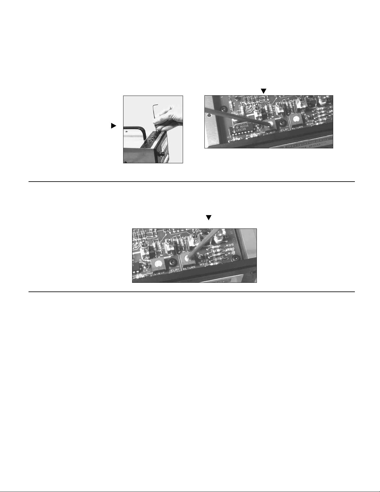
Circuit Board Adjustment
Strip Delay
Return Delay
It may be desirable to increase the time delay after cutting/gripping and
before pulling the slug off a wire. This will insure a more secure grip
and a better cut.
1. Remove the six #6-32 button head
cap screws (use 5/64 hex wrench)
and the top plate. Locate the circuit
board near the front of the unit.
2. Locate and adjust the “strip” delay by turning the potentiome-
ter screw with a small electronic screwdriver. Clockwise (+) to
increase delay and counterclockwise (-) to reduce delay.
3. Cycle the machine and continue to readjust as required.
4. Replace top plate.
It may be desired to increase the time delay after stripping a wire to
allow the operator more time to remove the wire before the unit resets
itself.
1. Remove the six #6-32 button head cap
screws (use 5/64 hex wrench) and the
top plate. Locate the circuit board near
the front of the unit.
2. Locate and adjust the “return” delay by turning the potentiom-
eter screw with a small electronic screwdriver. Clockwise (+) to
increase delay and counterclockwise (-) to reduce delay.
3. Cycle the machine and continue to read
just as required.
4. Replace top plate.
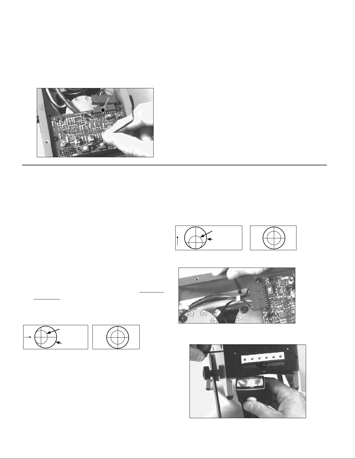
Service (Qualified personnel only; continued)
Circuit Board Adjustment
Replacement Circuit Board
Stripmaster®Model 950™ & 950-1™ Wire Strippers
Alignment Adjustments
Alignment
WIRE HARNESS CONNECTION
It may become necessary to replace the circuit board, in the unlikely
event of an electrical failure.
Your IDEAL Stripmaster®Model 950™ Wire Stripper has been aligned by IDEAL. After time, it may become necessary to realign. The following section
describes three different adjustments that are necessary to insure proper blade and guide alignment.
Adjustment Vertical
1. Remove top plate and slug tray.
2. Close blades using set up switch at top of machine.
It is helpful to use a light source beneath the machine to
illuminate the hole through the blade and bushing. Visually
check bushing and blade cutting holes for proper alignment.
3. Adjust set screws (use 1/16” hex wrench) located near both side
plates approximately 3 1/2” from the face plate, to raise or lower all
six blades to their proper vertical position if needed. Adjust both
sides evenly.
4. Install slug tray and top plate.
Adjustment Horizontal
1. Remove slug tray.
2. Close blades using set up switch at top of machine. It is
helpful to use a light source beneath the machine to illuminate the
hole through the blade and bushing. Visually check bushing and
blade cutting holes for proper alignment.
3. By turning both front left and front right set screws (use 3/32 hex wrench), repo-
sition the carriage left or right to obtain the proper alignment.
4. Install slug tray.
Important: Minimal side play is required for proper
alignment. But over tightening set screws will prohibit
carriage movement.
1. Remove the six #6-32 button head cap screws (use 5/64 hex
wrench) and the top plate. Locate the circuit board near the front
of the unit.
2. Remove the wire harness connector at the rear of the circuit
board.
3. Remove the four #6-32 button head cap screws (use 5/64 hex
wrench) on the circuit board.
4. Install the new circuit board and reverse removal procedures.
INCORRECT CORRECT
BLADE HOLE
GUIDE HOLE
9
INCORRECT CORRECT
BLADE HOLE
GUIDE HOLE

10
Stripmaster®Model 954™ Permanent Gripper Wire Stripper
Your IDEAL Stripmaster®Model 954™ Permanent Gripper Wire Stripper has been aligned by IDEAL. After time, it may become necessary to realign.
The following section describes three different adjustments that are necessary to insure proper blade and clamp bar alignment.
Permanent Gripper Faceplate
Adjustments Permanent
Faceplate Vertical
1. Remove top plate and slug tray.
2. Close blades using set up switch at top of machine. It is helpful to
use a light source beneath the machine to illuminate the hole through the
blade and bushing. Visually check bushing and blade cutting holes for
proper alignment.
3. Adjust set screws (use 1/16” hex wrench) located near both side plates
approximately 3 1/2” from the face plate, to raise or lower all six blades to
their proper vertical position if needed. Adjust both sides evenly.
4. Install slug tray and top plate.
Adjustments Permanent Faceplate Horizontal
1. Remove slug tray.
2. Close blades using set up switch at top of machine. It is helpful to use a light source beneath the machine to illuminate the hole through the blade
and bushing. Visually check bushing and blade cutting holes for proper alignment.
3. By turning both front left and front right set screws (use 3/32 hex wrench), reposition the carriage left or right to obtain the proper alignment.
4. Install slug tray.
Adjustments Permanent Faceplate Clamp Bar
1. With air connected to machines, turn power off and remove slug tray.
2. To raise gap of the clamp bar, turn setscrews clockwise. To reduce gap of the clampbar, turn setscrews counter-clockwise.
3. Replace Slug tray.
Note: Over extending one or both setscrews may result in wire being “pulled” into the machine during the stripping action. Not enough setscrew adjustment
could result in an excessive amount of clamping force resulting in damage to outer insulation.
Service (Qualified personnel only; continued)
Alignment Adjustments (continued)
Adjustments Clamp Yoke Stop
1. With air connected to machine, turn power off and remove slug tray.
It is again helpful to use a light source positioned at or between blade and
trigger area to illuminate the hole through the blade and bushing.
2. With blades in open position, look through all wire guides to see if blades are
obstructing the wire entry path. No part of the blade should be
visible.
3. If an adjustment is needed, disconnect the air supply and raise or lower clamp
yoke stop screws evenly (use 7/64 hex wrench). This will raise or lower blades,
thus ensuring a clear path for wire entry in all six bushings.
4. Insert slug tray.
INCORRECT CORRECT
BLADE EDGES
GUIDE HOLE
INCORRECT CORRECT
BLADE HOLE
GUIDE HOLE
INCORRECT CORRECT
BLADE HOLE
GUIDE HOLE
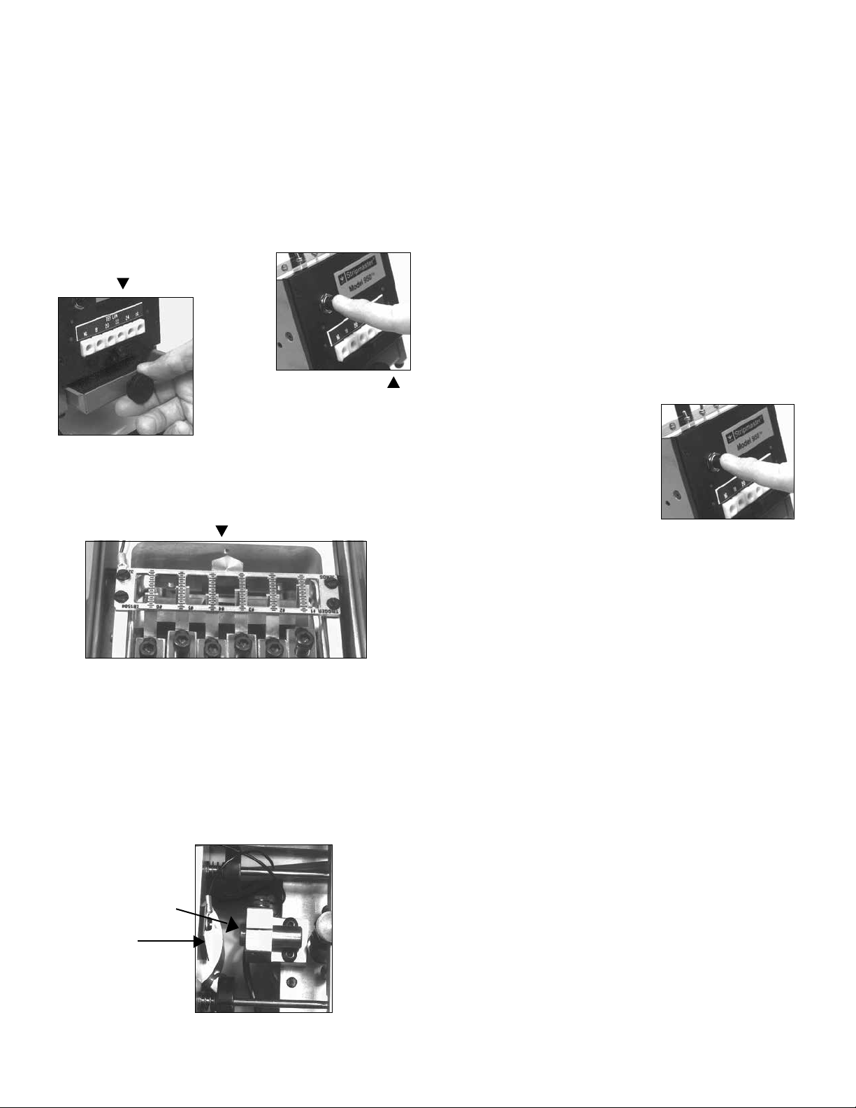
THIS PIN SHOULD
CONTACT THIS
PLATE DURING
CYCLE
11
Tips and Troubleshooting
CAUTION: Always disconnect air and power supply before ser-
vicing unit.
UNIT WILL NOT CYCLE
n Actuate manual switch.
n Check to see that you have proper air supply.
n Empty slug tray and make sure all slugs have
been removed from the unit.
n Check to see that no slugs are
trapped in the blade or trigger area. If
a slug is present, clear with a blast of
air (Item 11)*.
n Check to see that all triggers are clean and making necessary
contact with the contact plate (Item 19)*. These surfaces should be
lubricated with IDEAL Noalox®Anti-Oxidant: Part number 30-024.
Unit Will Not Cycle Remaining in Tripped Position
n Actuate manual switch.
n Check basket stop pin to see that contact is being made.
n Check basket stop pin and carriage plate contact for excessive
wear or contamination. Wipe both mating surfaces clean.
n Insure basket stop contact wire is properly connected and not broken.
Multiple or Continuous Cycling
On occasion the unit may repeat cycles while clearing a slug. If the con-
dition becomes excessive, the following steps may help you in identifying
and eliminating the problem.
n Make sure stripped wire is removed promptly after each cycle.
n Empty the slug removal tray and make sure that all slugs have been
removed from the unit.
n Disconnect the unit from the air and power supply and check to see that
no insulation slugs are trapped between the blades and triggers.
n If a slug is trapped, remove carefully.
Unit Will Not Strip Wire
n Use air switch slug blast (Item 11)* to clear any slugs away from the
blade/guide area and manually actuate the
machine.
n Check to see that the wire is being
inserted into the proper wire guide/blade.
n Check to see that the wire being used is
proper mil. spec. and within the proper
tolerance.
n Insure proper alignment and installation of blades (see Blade and Wire
Guide Installation).
n Check to see that the blades and wire guides are not damaged or worn.
If there is any question, replace the affected guides and blades or
consult IDEAL.
Wire Strip is Incomplete or Damages the Conductor
n Use air switch slug blast (Item 11)* to clear any slugs away from the
blade/guide area and manually actuate the machine.
n Check to see that the wire is being inserted into the proper guide/
blade.
n Check to see that the wire being used is proper mil. spec. and within
the proper tolerance.
n Insure proper alignment and installation of blades (see Blade and Wire
Guide Installation).
n Check to see that the blades and wire guides are not damaged or worn.
If there is any question, replace the affected guides and blades or con-
sult IDEAL.

1 2 3 4 5 6
LABEL FORMAT
1 Single Line
2 Single line Plus
3 Double Line Plus
4 Character max each
port
Top line 30 character
max. 4 character max.
each port
5 character max. each
line each port
Wire Information
AWG Insulation Mil Spec Stripping Comments
1
2
3
4
5
6
Comments
Ordering Blades and Wire Guides
Due to varying manufacturing techniques, standard wire gauge sizes have begun to indicate “nominal” wire sizes and no longer indicate conductor
diameters accurately. Therefore, in order to maintain accurate precision wire stripping, IDEAL requests that exact mil spec. information for the types of
wire and insulation you will be stripping be provided to IDEAL when ordering blades and wire guides.
IDEAL also requests wire samples when ordering. If an IDEAL Custom Stripmaster™ Wire Stripper® hand tool is currently being used to strip the par-
ticular wire please specify the blade number being used with each wire type and size.
Due to varying outside diameter dimensions on every wire, IDEAL recommends ordering multiple wire guide bushings to match a given wire.
Depending upon wire tolerances, it may be necessary to order a wire guide one size larger and one size smaller than supplied with the machine. Guides
are easily interchanged to match varied wire size
When ordering, please specify the preferred face plate location and number designation for each blade/guide set.
For larger wire sizes (e.g. 10 AWG, 12 AWG, 14 AWG) blade location is preferred in the center ports of the machine.
Specification Chart Instructions
List the wire size, insulation type and mil. spec. per each wire size and type for which you are ordering stripping blades and wire guides under the
location/s (1 thru 6) you prefer.
Indicate numerical wire gauge legends (10 thru 30) or any identification you wish to appear above each corresponding air guide/blade configuration.
(Choose and complete the desired label format below. 1, 2 or 3)
Note: For better stripping results, locate 10, 12, 14 gauge wires nearest to center ports.
12
13
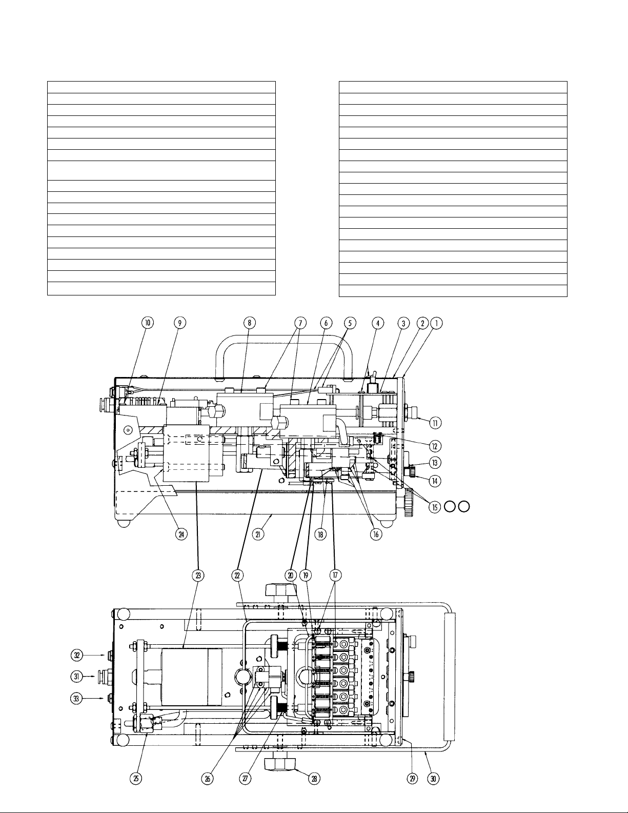
ITEM REQ NAME PART NO.
1 1 FRONT PLATE ASSEMBLY IA1819
2 1 TOP PLATE ASSEMBLY LB1523RP
3 1 CIRCUIT BOARD ASSEMBLY K-7109
4 14 SCREW #6-32 X .25 BHCS 115.002
5 1 WIRE HARNESS IA1892
6 1 BLADE CYLINDER ASSEMBLY K-7124RP
7 4 SCREW 113.095
#10-32 X 1.50 SHCS
8 1 CLAMP CYLINDER ASSEMBLY K-6863RP
9 2 SOLENOID VALVE 1532.007
10 4 SCREW #6-32 X 1.00 BHCS 115.028
11 1 AIR SWITCH SLUG BLAST LB1524
12 2 SPRING LB1513
13 1 BUSHING RETAINING PLATE K-6940
14 1 RETAINING SCREW LB1525
15 1 BLADE HOLDER H-2472
16 6 TRIGGER ASSEMBLY LB1526RP
17 5 SCREW #4-40 X .25 PH NYLON 358.033
ITEM REQ NAME PART NO.
18 4 WASHER #4 NYLON 637.006
19 1 CONTACT PLATE LB1504
20 1 CUT YOKE K-6806
21 1 SLUG TRAY ASSEMBLY K-7112RP
22 1 YOKE CLAMP K-6800
23 1 STRIP CYLINDER ASSEMBLY K-6864RP
24 2 SCREW #10-32 X 2.00 SHCS 113.096
25 1 AIR BLAST VALVE ASSEMBLY K-7153RP
26 1 BASKET STOP ASSEMBLY LB1527RP
27 2 SPRING LB1514
28 2 KNOB 341.016
29 4 SCREW #6-32 X .38 SHCS 113.100
30 1 HANDLE LB1528RP
31 1 AIR HOSE K-6865
32 1 PLUG-IN TRANSFORMER K-7156
BLADE MOUNTING SCREWS 115.010
BLADE MOUNTING WASHERS 633.051
NAMEPLATE HOLDER LA-2675
NOT SHOWN
NOT SHOWN
NOT SHOWN
NOT SHOWN
MANUAL SLUG BLAST
34 35
Stripmaster®Model 950™

Notes:

Notes:

IDEAL INDUSTRIES, INC.
1375 Park Avenue, Sycamore, IL 60178 – 800-435-0705 in U.S.A.
Ajax, Ontario, L1S 2E1, Canada – 800-527-9105 in Canada
Warrington, Cheshire WA55TN, England – 44 1925 444.446
www.idealind.com
Warranty limited solely to repair or replacement; no warranty of merchantability, fitness for a particular purpose or consequential damages.
1000 Park Avenue, Sycamore, IL 60178 — Manufacturing facility
Rev. 12/15
Printed in U.S.A.
Form No. ND 3558-2
©2015 IDEAL INDUSTRIES, INC.
This manual suits for next models
4
Table of contents


