Frama AF User manual

Service Manual –
Automatic Feeder Matrix AF / AFS
English Version

FRAMA AG
CH-3438 LAUPERSWIL / BERN
TITLE:
SERVICE MANUAL
SUB ECT: AU OMA IC FEEDER MA RIX AF / AFS
AUTHOR(S): ROLAND BÄR SCHI (BAER)
FILE: PER_MAN_R0102_EN_SERVICE MANUAL AF_AFS.DOC
DOC. REF:
DOC. R01.02
CREATED
:
31.10.13 16:10
MODIFIED: 19.11.13 13:11 PAGE
2
OF 40

FRAMA AG
CH-3438 LAUPERSWIL / BERN
TITLE:
SERVICE MANUAL
SUB ECT: AU OMA IC FEEDER MA RIX AF / AFS
AUTHOR(S): ROLAND BÄR SCHI (BAER)
FILE: PER_MAN_R0102_EN_SERVICE MANUAL AF_AFS.DOC
DOC. REF:
DOC. R01.02
CREATED
:
31.10.13 16:10
MODIFIED: 19.11.13 13:11 PAGE
3
OF 40
Service Manual
Automatic Feeder Matrix AF / AFS
R01.02
31.10.2013
AU HOR(S): Roland Bärtschi (baer)
---For internal use only---

FRAMA AG
CH-3438 LAUPERSWIL / BERN
TITLE:
SERVICE MANUAL
SUB ECT: AU OMA IC FEEDER MA RIX AF / AFS
AUTHOR(S): ROLAND BÄR SCHI (BAER)
FILE: PER_MAN_R0102_EN_SERVICE MANUAL AF_AFS.DOC
DOC. REF:
DOC. R01.02
CREATED
:
31.10.13 16:10
MODIFIED: 19.11.13 13:11 PAGE
4
OF 40
Document Overview
The following table shows in a short form the Intention of this document. There all instances (target readers)
mentioned where this document is intended for. The point restrictions shows which points or themes are not treated
in this document. Any points or themes with reference to other documents are mentioned under the point
references.
Document Overview
Document Content/Goal: Service Manual
Intended for: Technical staff, trained on the Frama AG Matrix MOL and TOL franking system.
Restrictions:
References:
Document History
The following table records all changes that were made in this document. In case of little changes (e.g. format,
spelling, minor corrections or omissions) the version number after the [.] has to be incremented. For important
changes (e.g. content) the version number before the [.] has to be increased.
Date
Version
Action
Authors
11.08.2011 D01.00 Creation baer
08.12.2011 R01.00 Release baer
26.03.2013 R01.01 Tool list (10.3.2) with thickness gauge completed baer
19.11.2013 R01.02 New tool 1019410 for separator lever adjustment
added. Setting value changed to 0.2mm (Chapter
10.3.1)
baer

FRAMA AG
CH-3438 LAUPERSWIL / BERN
TITLE:
SERVICE MANUAL
SUB ECT: AU OMA IC FEEDER MA RIX AF / AFS
AUTHOR(S): ROLAND BÄR SCHI (BAER)
FILE: PER_MAN_R0102_EN_SERVICE MANUAL AF_AFS.DOC
DOC. REF:
DOC. R01.02
CREATED
:
31.10.13 16:10
MODIFIED: 19.11.13 13:11 PAGE
5
OF 40
L
IST OF
C
ONTENT

FRAMA AG
CH-3438 LAUPERSWIL / BERN
TITLE:
SERVICE MANUAL
SUB ECT: AU OMA IC FEEDER MA RIX AF / AFS
AUTHOR(S): ROLAND BÄR SCHI (BAER)
FILE: PER_MAN_R0102_EN_SERVICE MANUAL AF_AFS.DOC
DOC. REF:
DOC. R01.02
CREATED
:
31.10.13 16:10
MODIFIED: 19.11.13 13:11 PAGE
6
OF 40
1.
IN RODUC ION ............................................................................................................................ 8
1.
IN RODUC ION ............................................................................................................................ 8
2.
SECURI Y NO ES .......................................................................................................................... 9
3.
AU OMA IC FEEDER SPECIFICA ION ....................................................................................... 10
4.
AU OMA IC FEEDER MA RIX AF AND AFS ............................................................................. 11
4.1.
Parts designation .................................................................................................................... 11
4.1.1.
Table Right TR and Table Left TL......................................................................................................... 13
5.
ELEC RONICS .............................................................................................................................. 14
6.
LIGH BARRIER DIAGNOS IC ES ............................................................................................ 15
6.1.
Test Feeder Matrix AF / AFS .................................................................................................... 15
6.2.
Position of Light Barriers in Feeder Matrix AF / AFS ................................................................. 16
7.
SOF WARE UPDA E ................................................................................................................... 16
8.
DISASSEMBLING FEEDER MA RIX AF / AFS ............................................................................. 17
8.1.
Upper Mechanics .................................................................................................................... 19
8.1.1.
Disassembling Clutch of Separator Roller ............................................................................................ 21
8.2.
Lower mechanics .................................................................................................................... 22
8.3.
Removing the Main Board ...................................................................................................... 23
8.4.
Exchange of the grey intake rollers ......................................................................................... 23
8.5.
Exchange of the red intake rollers ........................................................................................... 24
8.6.
Exchange of the transport rollers ............................................................................................ 25
8.7.
Exchange of the motor for the red intake rollers ..................................................................... 25
8.8.
Exchange of the motor for the stack rollers ............................................................................ 26
8.9.
Exchange of the motor for the transport rollers ...................................................................... 27
9.
ASSEMBLING FEEDER MA RIX AF / AFS ................................................................................... 28
9.1.
Lower mechanics .................................................................................................................... 28
9.2.
Upper mechanics .................................................................................................................... 29
9.3.
Assembling upper & lower mechanics .................................................................................... 31
10.
ADJUS MEN S............................................................................................................................ 32
10.1.
Separation roller ..................................................................................................................... 32
10.2.
Belts ....................................................................................................................................... 33
10.2.1.
Belt – Transport Rollers ................................................................................................................... 33
10.2.2.
Belt - Stack Rollers .......................................................................................................................... 33
10.2.3.
Belt - Motor transmission ............................................................................................................... 34
10.2.4.
Belt – Manual Control for correct belt tension................................................................................. 34
10.3.
Adjustment of Separator Levers .............................................................................................. 35
10.3.1.
Adjustment of lever retarded motion .............................................................................................. 36
10.3.2.
Tool list .......................................................................................................................................... 36
11.
MAIN ENANCE INS RUC ION ................................................................................................... 37
11.1.
General measures ................................................................................................................... 37
11.2.
Cleaning of the Rubber Rollers ............................................................................................... 37
11.3.
Lubrication chart .................................................................................................................... 37
11.4.
General information about the lubrication method ................................................................. 38
11.5.
Lubrication for after sales service ............................................................................................ 38
11.6.
Bearing and lever joints .......................................................................................................... 38
12.
NO ES – MA RIX FEEDER AF / AFS ........................................................................................... 39

L
IST OF
P
ICTURE

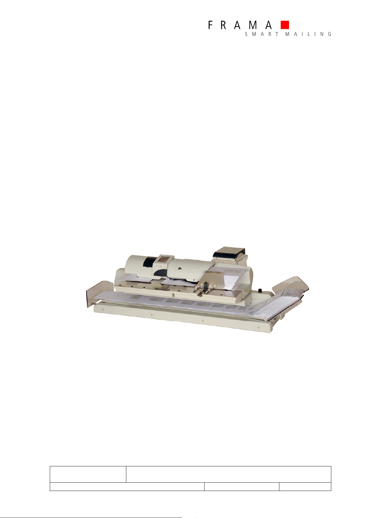
Figure 1 - Matrix F8 with Feeder AFS, Extension Table TR / TL ..................................................................................... 9
Figure 2: Parts Designation ...................................................................................................................................... 12
Figure 3: Parts Designation ...................................................................................................................................... 12
Figure 4: Parts Designation ...................................................................................................................................... 12
Figure 5: Parts Designation ...................................................................................................................................... 13
Figure 6: Parts Designation ...................................................................................................................................... 13
Figure 7: Parts Designation ...................................................................................................................................... 13
Figure 8: Parts Designation ...................................................................................................................................... 14
Figure 9: Parts Designation ...................................................................................................................................... 14
Figure 10: Main Board AF and AFS .......................................................................................................................... 15
Figure 11: Connector board AF and AFS .................................................................................................................. 15
Figure 12: Service Diagnostic ................................................................................................................................... 16
Figure 13: Service Diagnostic ................................................................................................................................... 17
Figure 14: Separation Matrix – Feeder ...................................................................................................................... 18
Figure 15: Removing – Sealer Unit ........................................................................................................................... 18
Figure 16: Disassembling – Top Cover ...................................................................................................................... 18
Figure 17: Disassembling - Upper Mechanics ........................................................................................................... 19
Figure 18: Disassembling – Upper Mechanics ........................................................................................................... 19
Figure 19: Disassembling - Upper Mechanics ........................................................................................................... 19
Figure 20: Disassembling - Upper Mechanics ........................................................................................................... 20
Figure 21: Disassembling – Upper Mechanics ........................................................................................................... 20
Figure 22: Disassembling - Upper Mechanics ........................................................................................................... 20
Figure 23: Disassembling - Label Dispenser .............................................................................................................. 21
Figure 24: Disassembling - Label Dispenser .............................................................................................................. 21
Figure 25: Disassembling – Clutch Separator ............................................................................................................ 22
Figure 26: Disassembling – Clutch Separator ............................................................................................................ 22
Figure 27: Disassembling - Lower Mechanics ........................................................................................................... 23
Figure 28: Disassembling – Lower Mechanics ........................................................................................................... 23
Figure 29: Disassembling - Lower Mechanics ........................................................................................................... 23
Figure 30: Disassembling - Main PCB ....................................................................................................................... 24
Figure 31: Disassembling – Gray Intake Rollers ......................................................................................................... 24
Figure 32: Disassembling - Gray Intake Rollers ......................................................................................................... 24
Figure 33: Disassembling - Red Intake Rollers ........................................................................................................... 25
Figure 34: Disassembling - Red Intake Rollers ........................................................................................................... 25
Figure 35: Disassembling - Red Intake Rollers ........................................................................................................... 25
Figure 36: Disassembling - Transport Rollers ............................................................................................................ 26
Figure 37: Disassembling - Transport Rollers ............................................................................................................ 26
Figure 38: Disassembling - Motor Replacement ........................................................................................................ 26
Figure 39: Disassembling - Motor Replacement ........................................................................................................ 27
Figure 40: Disassembling - Motor Replacement ........................................................................................................ 27
Figure 41: Disassembling - Motor Replacement ........................................................................................................ 27
Figure 42: Disassembling - Motor Replacement ........................................................................................................ 28
Figure 43: Disassembling - Motor Replacement ........................................................................................................ 28
Figure 44: Disassembling - Motor Replacement ........................................................................................................ 28
Figure 45: Assembling - Lower Mechanics ............................................................................................................... 29
Figure 46: Assembling - Lower Mechanics ............................................................................................................... 29
Figure 47: Assembling - Lower Mechanics ............................................................................................................... 29
Figure 48: Assembling - Label Dispenser .................................................................................................................. 30
Figure 49: Assembling - Label Dispenser .................................................................................................................. 30
Figure 50: Assembling - Upper Mechanics ............................................................................................................... 30
Figure 51: Assembling - Upper Mechanics ............................................................................................................... 31
Figure 52: Assembling - Upper Mechanics ............................................................................................................... 31
Figure 53: Assembling – Upper & Lower Mechanics ................................................................................................. 31
Figure 54: Assembling - Upper & Lower Mechanics .................................................................................................. 32
Figure 55: Assembling – Upper & Lower Mechanics ................................................................................................. 32
Figure 56: Assembling - Top Cover .......................................................................................................................... 32
Figure 57: Adjustments - Separation Roller .............................................................................................................. 33
Figure 58: Adjustments – Separation Roller .............................................................................................................. 33
Figure 59: Adjustments - Separation Roller .............................................................................................................. 33
Figure 60: Adjustments - Belt................................................................................................................................... 34
Figure 61: Adjustments - Belt................................................................................................................................... 34
Figure 62: Adjustments - Belt................................................................................................................................... 35
Figure 63: Adjustments - Belt................................................................................................................................... 35
Figure 64: Adjustments – Separator Lever ................................................................................................................ 36
Figure 65: Adjustments – Separator Lever ................................................................................................................ 36

Figure 66: Adjustments – Separator Lever ................................................................................................................ 36
Figure 67: Adjustments - Belt................................................................................................................................... 37

FRAMA AG
CH-3438 LAUPERSWIL / BERN
TITLE:
SERVICE MANUAL
SUB ECT: AU OMA IC FEEDER MA RIX AF / AFS
AUTHOR(S): ROLAND BÄR SCHI (BAER)
FILE: PER_MAN_R0102_EN_SERVICE MANUAL AF_AFS.DOC
DOC. REF:
DOC. R01.02
CREATED
:
31.10.13 16:10
MODIFIED: 19.11.13 13:11 PAGE
10
OF 40
1. Introduction
This document, provided by Frama AG, contains general technical information of the automatic Feeder
Matrix AF and AFS. Furthermore it includes a detailed description for the disassembling and assembling
procedure.
This document is mainly designed for technical staff and is based on the technical training performed by
Frama AG.
Subject to change without notice.
Related documents:
Spare parts manual: Version R03.00 and update R04.00
Operating guide: Frama Matrix F8
Figure 1 - Matrix F82 with Feeder AFS, Extension able R / L
and Conveyer Stacker CF

FRAMA AG
CH-3438 LAUPERSWIL / BERN
TITLE:
SERVICE MANUAL
SUB ECT: AU OMA IC FEEDER MA RIX AF / AFS
AUTHOR(S): ROLAND BÄR SCHI (BAER)
FILE: PER_MAN_R0102_EN_SERVICE MANUAL AF_AFS.DOC
DOC. REF:
DOC. R01.02
CREATED
:
31.10.13 16:10
MODIFIED: 19.11.13 13:11 PAGE
11
OF 40
2. Security Notes
he franking system must be turned off before removing or replacing any
periphery devices!
By open machine avoid touch moving parts while the system is in operation!
Observe precautions for handling electrostatic sensitive parts!

FRAMA AG
CH-3438 LAUPERSWIL / BERN
TITLE:
SERVICE MANUAL
SUB ECT: AU OMA IC FEEDER MA RIX AF / AFS
AUTHOR(S): ROLAND BÄR SCHI (BAER)
FILE: PER_MAN_R0102_EN_SERVICE MANUAL AF_AFS.DOC
DOC. REF:
DOC. R01.02
CREATED
:
31.10.13 16:10
MODIFIED: 19.11.13 13:11 PAGE
12
OF 40
3. Automatic Feeder Specification
Franking per hour: 8500 letters / h (C6)
Maximum envelop thickness: 10 mm
Operating Noise: 53.8 dBA (Matrix TOL and Feeder AFS)
Dimensions
Dimensions AFS: 515 x 217 x 205 mm
Wight: 9,0kg
Power consumption
Matrix F8 / AFS: Standby 12,6Watt
In Operation: 54Watt
Nominal data power supply
Automatic feeder AFS: 90-264V AC, 47-62Hz, 0,75A, T2A fused
Matrix Feeder ypes:
AF Matrix Feeder without envelope seal function
AFS Matrix Feeder with envelope seal (S) function

FRAMA AG
CH-3438 LAUPERSWIL / BERN
TITLE:
SERVICE MANUAL
SUB ECT: AU OMA IC FEEDER MA RIX AF / AFS
AUTHOR(S): ROLAND BÄR SCHI (BAER)
FILE: PER_MAN_R0102_EN_SERVICE MANUAL AF_AFS.DOC
DOC. REF:
DOC. R01.02
CREATED
:
31.10.13 16:10
MODIFIED: 19.11.13 13:11 PAGE
13
OF 40
4. Automatic Feeder Matrix AF and AFS
This section provides a general overview of the Feeder Matrix AF / AFS. It comprises a description for
disassembling / assembling and adjustments as well as recommendations for maintenance.
4.1. Parts designation
1. Side stop
2. Letter separation roller
3. Letter stack roller
4. Letter vibrator roller
5. Water tank
6. Label dispenser device
7. Docking mechanism extension
table (5x) TR and TL
Figure 2: Parts Designation
1. Letter separator roller
2. Additional separator roller for big
size letter
3. Label dispenser unit
4. Additional separator lever for big
sized enveloped
Figure 3: Parts Designation
1.
Separator roller
2. Clutch
Figure 4: Parts Designation
4
2
3
5
6
1
7
1
2
3
4
1
2

FRAMA AG
CH-3438 LAUPERSWIL / BERN
TITLE:
SERVICE MANUAL
SUB ECT: AU OMA IC FEEDER MA RIX AF / AFS
AUTHOR(S): ROLAND BÄR SCHI (BAER)
FILE: PER_MAN_R0102_EN_SERVICE MANUAL AF_AFS.DOC
DOC. REF:
DOC. R01.02
CREATED
:
31.10.13 16:10
MODIFIED: 19.11.13 13:11 PAGE
14
OF 40
1. Motor 1 Transport-rollers
2. Motor 2 Intake-rollers (red)
3. Motor 3 Stack drive-rollers (grey)
4. Light barrier motor start and short letter
control
5. Letter release lever
6. Main board feeder
Figure 5: Parts Designation
1.
Connector board
.
Power and Data supply for Matrix
system
2. Power supply
3. Main power socket with fuse
Figure 6: Parts Designation
1. Fissile wedge.
2. Seal unit
Figure 7: Parts Designation
2
1
1
2
3
1
2
3
4
5
6

FRAMA AG
CH-3438 LAUPERSWIL / BERN
TITLE:
SERVICE MANUAL
SUB ECT: AU OMA IC FEEDER MA RIX AF / AFS
AUTHOR(S): ROLAND BÄR SCHI (BAER)
FILE: PER_MAN_R0102_EN_SERVICE MANUAL AF_AFS.DOC
DOC. REF:
DOC. R01.02
CREATED
:
31.10.13 16:10
MODIFIED: 19.11.13 13:11 PAGE
15
OF 40
4.1.1. able Right R and able Left L
Table TR
Only available for matrix F8 system
Figure 8: Parts Designation
Table TL
Only available for Matrix F8 system
Figure 9: Parts Designation

FRAMA AG
CH-3438 LAUPERSWIL / BERN
TITLE:
SERVICE MANUAL
SUB ECT: AU OMA IC FEEDER MA RIX AF / AFS
AUTHOR(S): ROLAND BÄR SCHI (BAER)
FILE: PER_MAN_R0102_EN_SERVICE MANUAL AF_AFS.DOC
DOC. REF:
DOC. R01.02
CREATED
:
31.10.13 16:10
MODIFIED: 19.11.13 13:11 PAGE
16
OF 40
5. Electronics
Figure 10: Main Board AF and AFS
Figure 11: Connector board AF and AFS
kçK
=
aÉëÅêáéí
áçå
=
kçK
=
aÉëÅêáéíáçå
=
1
Motor
–
Intake
-
rollers (red)
11
Water
-
level sensor
2
Motor
–
Intake
-
rollers (
grey
)
12
Sensor
–
Solenoid sealer
3
Motor
–
Transport
-
rollers
15
Water
-
tank sensor
4
Power supply
16
Light barrier BA1 and BA2
5
Connector board
17
Ma
in board
6
Light barrier
–
Motor intake
-
rollers (red)
18
Label dispenser motor and light barrier
7
Light barrier
–
Motor transport
A
Data cable (grey)
8
Light barrier
–
Motor intake
-
rollers (
grey
)
9
Solenoid sealer
10
Light barrier
–
Release lev
er
15
16
17
A
18
1
2
3
4
5
6
7
8
9
10
11
12
A
1

FRAMA AG
CH-3438 LAUPERSWIL / BERN
TITLE:
SERVICE MANUAL
SUB ECT: AU OMA IC FEEDER MA RIX AF / AFS
AUTHOR(S): ROLAND BÄR SCHI (BAER)
FILE: PER_MAN_R0102_EN_SERVICE MANUAL AF_AFS.DOC
DOC. REF:
DOC. R01.02
CREATED
:
31.10.13 16:10
MODIFIED: 19.11.13 13:11 PAGE
17
OF 40
6. Light barrier diagnostic test
During the start up procedure a check of all light barriers will be automatically performed. In case of an
occurring malfunction an error code will be displayed. It is possible to display the status of each light
barrier to facilitate the error searching. Therefore, press the service button as soon an error is displayed.
As an example, the following display should be displayed:
6.1. est Feeder Matrix AF / AFS
Figure 12: Service Diagnostic
S: Light barrier stack release switch
1 = Light barrier active
0 = Light barrier inactive
L: Sensor water level
0 = Light barrier active (tank empty)
1 = Light barrier inactive (tank full)
: Light barrier water tank
0 = Light barrier active (tank inserted)
1 = Light barrier inactive (tank removed)
M: Sensor solenoid
0 = Light barrier active (magnet falling
off)
1 = Light barrier inactive (magnet
attracted)
B: Light barriers
Position: Letter table BA2
1 = Light barrier active
0 = Light barrier inactive
2. Position: Letter table BA1
1 = Light barrier active
0 = Light barrier inactive
E: Light barrier motor transmitters
1. Transmitter motor transport
0 = Light barrier active
1 = Light barrier inactive
2. Transmitter motor separation
0 = Light barrier active
1 = Light barrier inactive
3. Transmitter motor intake
0 = Light barrier active
1 = Light barrier inactive
--
F4/F6 service diagnostic
--
Error E0004
S:1 L:0 :0 M:1 B:01 E:010
S:0110 P:101 L:0 B :101 :10
--
F4/F6 service
diagnostic
--

FRAMA AG
CH-3438 LAUPERSWIL / BERN
TITLE:
SERVICE MANUAL
SUB ECT: AU OMA IC FEEDER MA RIX AF / AFS
AUTHOR(S): ROLAND BÄR SCHI (BAER)
FILE: PER_MAN_R0102_EN_SERVICE MANUAL AF_AFS.DOC
DOC. REF:
DOC. R01.02
CREATED
:
31.10.13 16:10
MODIFIED: 19.11.13 13:11 PAGE
18
OF 40
6.2. Position of Light Barriers in Feeder Matrix AF / AFS
Figure 13: Service Diagnostic
7. Software update
In case of a necessary software update on the AF and AFS feeder follow the instructions below:
Switch off the franking system.
Plug in the corresponding software box or USB memory stick to the Matrix F6 or F8.
Switch on the franking system. The machine detects a connected software box and checks the
content of the box. Afterwards, the machine starts to copy the box content and overwrites the
existing software version. This process takes approximately 4 minutes and can be followed by the
percentage bar.
Do not switch off the machine during the loading process!!! A power interruption
would cause a damage of the memories on the feeder main PCB.
After the successful loading of the new software switch off the machine and remove the loading
box.
At the restart of the machine the new software version should be shown in the display during the
start up procedure.
Note:
For some countries the software down load can be processed online (modem). The operator
needs to carry out an inspection load and in the situation a new feeder software version is
available the Matrix System starts the download automatically.
S
T
B1 B2
E1 E2
E3
L
M
Letter transport

FRAMA AG
CH-3438 LAUPERSWIL / BERN
TITLE:
SERVICE MANUAL
SUB ECT: AU OMA IC FEEDER MA RIX AF / AFS
AUTHOR(S): ROLAND BÄR SCHI (BAER)
FILE: PER_MAN_R0102_EN_SERVICE MANUAL AF_AFS.DOC
DOC. REF:
DOC. R01.02
CREATED
:
31.10.13 16:10
MODIFIED: 19.11.13 13:11 PAGE
19
OF 40
8. Disassembling Feeder Matrix AF / AFS
The section comprises a description of the dissembling procedure of the Feeder Matrix AF / AFS.
Turn off the device, disconnect the cord
from the rear of the periphery device
and separate the feeder as described in
the operating guide.
Note:
Never separate franking machine and
automatic feeder if they are switched
on!
Figure 14: Separation Matrix – Feeder
Remove the water tank on the back
side.
Remove the seal unit.
Figure 15: Removing – Sealer Unit
Unscrew and remove the four screws
underneath the flap and remove the
whole cover.
Figure 16: Disassembling – Top Cover
1

FRAMA AG
CH-3438 LAUPERSWIL / BERN
TITLE:
SERVICE MANUAL
SUB ECT: AU OMA IC FEEDER MA RIX AF / AFS
AUTHOR(S): ROLAND BÄR SCHI (BAER)
FILE: PER_MAN_R0102_EN_SERVICE MANUAL AF_AFS.DOC
DOC. REF:
DOC. R01.02
CREATED
:
31.10.13 16:10
MODIFIED: 19.11.13 13:11 PAGE
20
OF 40
Unscrew the three screws
(1)
which are
fixing the cover (2) and remove it.
Unhook the water level detection
sensor board which is snapped inside
the cover (2).
Figure 17: Disassembling - Upper Mechanics
Disconnect cable 18
(1)
from the
connector board.
Remove the two clips (2).
Move the locking lever (3) and lift up
the upper mechanics.
Remove both compression springs (4)
and pay attention for the washers.
Figure 18: Disassembling – Upper Mechanics
Figure 19: Disassembling - Upper Mechanics
1
2
4
3
1
2
This manual suits for next models
1
Table of contents
Popular Wire Feeder manuals by other brands

Textron
Textron Greenlee 6810 instruction manual

Neutrasafe
Neutrasafe NSSF6-2 Installation, operation and maintenance instructions

GALA
GALA D-12 A instruction manual

FRONIUS
FRONIUS WF 25i Case D200 Operating instructions/spare parts list

FRONIUS
FRONIUS VR 1530-11 operating instructions

Delta Regis
Delta Regis DRFF-530 OPERATION AND SETUP MANUAL