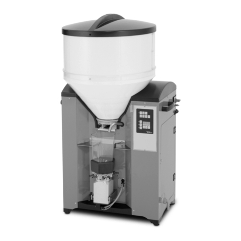
Graco G-Flex 1500 Instruction Manual

332462A
EN
Operation - Repair - Parts
G-Flex 1500 Feeder
- For professional use only -
Model 16V133 - 120V
Vibratory Parts Feeder for separating and presenting parts.
Important Safety Instructions
Read all warnings and instructions in this
manual. Save these instructions.
MAIN
POWER
TABLE HOPPER
ti21442a

2332462A
Contents
Warnings . . . . . . . . . . . . . . . . . . . . . . . . . . . . . . . . . 3
Component Identification . . . . . . . . . . . . . . . . . . . . 5
Installation . . . . . . . . . . . . . . . . . . . . . . . . . . . . . . . . 6
Floor Preparation . . . . . . . . . . . . . . . . . . . . . . . . 6
Lifting Instructions . . . . . . . . . . . . . . . . . . . . . . . . 6
Wiring Connections . . . . . . . . . . . . . . . . . . . . . . . 7
PLC Interface . . . . . . . . . . . . . . . . . . . . . . . . . . . 7
General Information . . . . . . . . . . . . . . . . . . . . . . . . 8
Control Menu . . . . . . . . . . . . . . . . . . . . . . . . . . . 8
Power Setting . . . . . . . . . . . . . . . . . . . . . . . . . . . 8
Auto Scan . . . . . . . . . . . . . . . . . . . . . . . . . . . . . . 8
Start-Up Procedure . . . . . . . . . . . . . . . . . . . . . . . . . 9
Perform Auto Scan . . . . . . . . . . . . . . . . . . . . . . . 9
Operation . . . . . . . . . . . . . . . . . . . . . . . . . . . . . . . . 10
Part Table Feed Rate . . . . . . . . . . . . . . . . . . . . 10
Hopper Feed Rate . . . . . . . . . . . . . . . . . . . . . . 10
Control Menu Layout . . . . . . . . . . . . . . . . . . . . . 12
Manual Operation in Override Mode . . . . . . . . . 13
Detailed Control Adjustment . . . . . . . . . . . . . . . . 13
Amplitude Power Setting . . . . . . . . . . . . . . . . . . 13
Limiting Maximum Output of Control . . . . . . . . . 13
Setting Minimum Output of Control . . . . . . . . . . 13
Soft-Start . . . . . . . . . . . . . . . . . . . . . . . . . . . . . . 13
CFR Positive and Negative Gain . . . . . . . . . . . 13
Frequency Settings . . . . . . . . . . . . . . . . . . . . . . 13
Resonate Threshold Level . . . . . . . . . . . . . . . . 14
AutoTrack Dead Band . . . . . . . . . . . . . . . . . . . . 14
Diagnostics . . . . . . . . . . . . . . . . . . . . . . . . . . . . 14
Security Settings . . . . . . . . . . . . . . . . . . . . . . . . 14
Default Memory . . . . . . . . . . . . . . . . . . . . . . . . . 14
Language . . . . . . . . . . . . . . . . . . . . . . . . . . . . . 14
Over Current Protection . . . . . . . . . . . . . . . . . . 14
CFR Set Point . . . . . . . . . . . . . . . . . . . . . . . . . . 15
Repair . . . . . . . . . . . . . . . . . . . . . . . . . . . . . . . . . . . 16
Power Disconnect . . . . . . . . . . . . . . . . . . . . . . . 16
Air Gap Specifications . . . . . . . . . . . . . . . . . . . . 16
Table and Brush Spacing . . . . . . . . . . . . . . . . . . 16
Table Adjustment . . . . . . . . . . . . . . . . . . . . . . . . 16
Brush Adjustment . . . . . . . . . . . . . . . . . . . . . . . 16
Electromagnet and Armature Spacing . . . . . . . . 17
Spring Replacement . . . . . . . . . . . . . . . . . . . . . 17
Electromagnet Replacement . . . . . . . . . . . . . . . 18
Display (Keypad) Replacement . . . . . . . . . . . . . 20
Accelerometer Replacement . . . . . . . . . . . . . . . 22
Troubleshooting . . . . . . . . . . . . . . . . . . . . . . . . . . . 24
Parts . . . . . . . . . . . . . . . . . . . . . . . . . . . . . . . . . . . . 25
Parts List . . . . . . . . . . . . . . . . . . . . . . . . . . . . . . 26
Wiring Diagram . . . . . . . . . . . . . . . . . . . . . . . . . . . 29
Technical Specifications . . . . . . . . . . . . . . . . . . . . 30
Box Wiring . . . . . . . . . . . . . . . . . . . . . . . . . . . . . 31
CFR Values Table . . . . . . . . . . . . . . . . . . . . . . . . . . 32
Notes . . . . . . . . . . . . . . . . . . . . . . . . . . . . . . . . . . . . 33
Graco Standard Warranty . . . . . . . . . . . . . . . . . . . 34

Warnings
332462A 3
Warnings
The following warnings are for the setup, use, grounding, maintenance, and repair of this equipment. The exclama-
tion point symbol alerts you to a general warning and the hazard symbols refer to procedure-specific risks. When
these symbols appear in the body of this manual or on warning labels, refer back to these Warnings. Product-specific
hazard symbols and warnings not covered in this section may appear throughout the body of this manual where
applicable.
WARNING
ELECTRIC SHOCK HAZARD
This equipment must be grounded. Improper grounding, setup, or usage of the system can cause electric
shock.
•
Turn off and disconnect power at main switch before disconnecting any cables and before servicing or
installing equipment.
•
Connect only to grounded power source.
•
All electrical wiring must be done by a qualified electrician and comply with all local codes and regula-
tions.
EQUIPMENT MISUSE HAZARD
Misuse can cause death or serious injury.
•
Do not operate the unit when fatigued or under the influence of drugs or alcohol.
•
Check equipment daily. Repair or replace worn or damaged parts immediately with genuine manufac-
turer’s replacement parts only.
•
Do not alter or modify equipment. Alterations or modifications may void agency approvals and create
safety hazards.
•
Make sure all equipment is rated and approved for the environment in which you are using it.
•
Use equipment only for its intended purpose. Call your distributor for information.
•
Route cables away from traffic areas, sharp edges, moving parts, and hot surfaces.
•
Keep children and animals away from work area.
•
Comply with all applicable safety regulations.
PERSONAL PROTECTIVE EQUIPMENT
Wear appropriate protective equipment when in the work area to help prevent serious injury, including eye
injury, hearing loss, and burns. This protective equipment includes but is not limited to:
•
Protective eyewear, and hearing protection.

Component Identification
4332462A
Component Identification
MAIN
POWER
TABLE HOPPER
C
D
F
EH
J
A
B
ti21443a
K
L
MN
P
QR
Ref. Description Ref. Description
A Parts Table Left Half K M12 Connector
B Parts Table Right Half L Fuses
C Adjustable Gate M Hopper Feed Table
D Parts Hopper N Electromagnet Left Half
E Lifting Points P Electromagnet Right Half
F Control Display and Touch Pad Q Electromagnet Hopper
H Main Power Switch/Lock Out R Power-in Junction Box
J Floor Mounting Plate

Lifting Instructions
332462A 5
Lifting Instructions
1. Always use BOTH designated mounted lifting lugs
when lifting the G-Flex 1500. See Component
Identification, page 4, for location of lifting lugs.
Installation
When choosing a location for the G-Flex 1500, make
sure the mounting plate is a minimum of 4 in. away from
any other piece of equipment. Refer to the anchor bolt
manufacturer for a minimum edge distance to the con-
crete slab. Follow local regulations in regards to spacing
for control panel access.
Floor Preparation
1. The G-Flex 1500 must be mounted on a level con-
crete surface.
2. To mount the G-Flex 1500 postition it in the desired
location. The G-Flex 1500 Floor Mounting Plate (J)
is designed to be anchored using four 3/8 in. con-
crete anchor bolts.
3. Use a concrete drill bit of the size recommended by
the anchor bolt manufacturer. Drill 4 holes in the
concrete using the Floor Mounting Plate holes as a
guide. Install the anchor bolts per the manufac-
turer’s instructions.
4. A minimum of 1 in. of stud length must protrude
from the floor for proper installation.
5. Install four washers (64) and four nuts (65) provided
to secure the G-Flex 1500 to the concrete surface.
6. Torque to anchor bolt manufacturer recommenda-
tion.
To prevent crush injury or equipment damage when lift-
ing the G-Flex
™
1500, only use approved (e.g., ANSI)
slings and equipment rated for the weight of the
G-Flex
™
1500 (see Technical Specifications, page
30).
ti21756a
ti21685a
ti21660a
ti21683a
ti21685a
64
65

Installation
6332462A
Wiring Connections
Supply Wiring Connections
Connect power to the G-Flex 1500 at the Power-in Junc-
tion Box (R). See Component Identification, page 4,
for location of Junction Box. Use a minimum of 14 AWG
solid wires from the power supply. Insulation strip length
is 0.43 in. (11 mm). Connect the Hot (L1), Neutral (N),
and Ground wires to coincide with the G-Flex 1500
wires at the terminal block.
Ensure all connections are secure and install the cover
on the junction box.
PLC Interface
The G-Flex 1500 is designed to be PLC controlled
through the M12 5-Pin connector. Refer to the M12 Pin
Diagram for details about the M12 connector. To run the
unit without PLC control, see Manual Operation in
Override Mode, 12.
M12 Pin Diagram
The table and hopper signal must be between 5-30
VDC. The common signal is 0 VDC.
All electrical wiring must be done by a qualified electri-
cian and comply with all local codes and regulations.
ti21441a
Connector on Housing Pin-out
ti21994a
(4)
(1)
(2)
(3)
(5)
1NotUsed
2 Table Signal
(5-30 VDC)
3Common
(0 VDC)
4 Hopper Signal
(5-30 VDC)
5GND

General Information
332462A 7
General Information
Control Menu
The control uses four programming keys to operate the
control. The power key controls manual operation in
override mode.
Power Setting
The G-Flex 1500 comes from the factory set to “Auto
Track” for both Amplitude Source and Frequency Mode.
This allows the user to adjust the CFR (Constant Feed
Rate) value to the desired feed rate. The control will
automatically adjust the Amplitude and the Frequency to
ensure a constant feed rate even as the parts load
changes. To show when frequency Auto Tracking is
enabled, the normal display menu will show a bold “F”.
When “=” is shown in bold, the control is locked onto the
resonate frequency of the table. The amplitude and fre-
quency can be changed to Manual adjustment if desired
(see Control Menu Layout, page 11).
Auto Scan
Before the G-Flex 1500 can be operated, the control
output frequency needs to be adjusted to match the nat-
ural frequency of both the tray and hopper. Auto Scan
locates the tray and hopper resonate frequency. Once
auto tracking has found the resonate frequency, it can
maintain the resonate frequency and amplitude as the
parts load changes. See Start-Up Procedure, page 8,
for Auto Scan Set Up.
Key Function
ENTER - Allows entry to menu and access to
adjust each setting. Push and hold the enter
key to enter program mode. If security feature
has been enabled, enter proper code. Once
inside the menu, the enter key selects a menu
item or a parameter to adjust. Any changes to
the settings are saved at power-down.
BACK - Moves the current menu location up
one level higher than it was before. It is also
used to get back to the normal operating dis-
play.
Arrow Down - Allows the user to step down
through the program menu or decrease a set-
ting.
Arrow Up - Allows the user to step up through
the program menu or increase a
setting.
Power - Allows the user to temporarily stop or
to start control operation. When the LCD status
reads “Stop/Run”, hold the power key down for
just over a second and the control will start the
override operation. In override mode, the hop-
per or table turns on regardless of input con-
nection and signal from the PLC at the M12.
NOTE: See Control Menu Layout, page 11, for the menu
structure. When in menu mode and no keys are pressed for
one minute, the display reverts to normal
operating display mode.

Start-Up Procedure
8332462A
Start-Up Procedure
Perform Auto Scan
1. Confirm no parts are on the table or in the hopper.
2. Ensure no person or thing is touching the unit.
3. Press main power switch to the ON position.
4. On the TABLE CONTROL TOUCH PAD, press and
hold the ENTER key to access the main menu.
5. Press DOWN ARROW to select the Frequency sub-
menu and press the ENTER key.
6. Press the UP ARROW three times to select Auto
Scan from the menu.
7. Press the ENTER key to perform an Auto Scan.
8. The table will cycle through different amplitudes and
frequency for about 15 seconds until the resonate
frequency has been found. If the resonate fre-
quency cannot be found, see Troubleshooting
page 23.
9. The table and hopper were Auto Scanned at manu-
facture. The serial label below the POWER IN
JUNCTION BOX (J) lists the natural frequency of
the table and hopper when the G-Flex 1500 was
manufactured.
10. Confirm the resonate frequency is between
60-67Hz. If it falls outside of this range, see Trou-
bleshooting page 23.
11. With the table running, press and hold the DOWN
ARROW key until the amplitude is set to a value of
0.0. CFR value will also read 000.0.
12. Press the POWER key on the TABLE CONTROL
TOUCH PAD to turn the part table OFF.
13. Repeat the Auto Scan procedure for the hopper
using the HOPPER CONTROL TOUCH PAD. The
resonate frequency for the hopper should be
between 70-95Hz.
14. With the hopper running, press and hold the DOWN
ARROW key until the amplitude is set to a value of
0.0 CFR value will also read 000.0
15. Press the POWER key on the HOPPER CONTROL
TOUCH PAD to turn the hopper OFF.
For a detailed explanation on all control settings, see
Detailed Control Adjustment, page 12.
***FIRST TIME USE ONLY***
Prior to performing the start-up procedure for the first
time confirm the two halves of the part table are not
touching. This is accomplished by sliding a spacer
down the center of the parts table in between the two
table halves. If the tables are touching see Air Gap
Specification, page 15.
ti21993a
ti21921a
ti21922a
ti21922a

Operation
332462A 9
Operation
BEFORE OPERATING THE G-FLEX 1500, AN AUTO
SCAN MUST BE PERFORMED TO FIND THE
RESONATE FREQUENCY OF THE TABLE AND THE
HOPPER. Refer to Startup Procedure, page 8.
Part Table Feed Rate
1. Place 4 to 20 parts on the table.
2. Turn the table on either through the M12 input or
manually, see Manual Operation in Override
Mode, page 12.
3. For course adjustment, PRESS AND HOLD the UP
or DOWN arrow key until the parts are moving close
to the desired feed rate. This directly changes the
Amplitude value.
4. For fine tune adjustment REPEATEDLY PRESS the
UP or DOWN arrow keys to dial in on the desired
feed rate. This directly changes the CFR Value.
5. Once the feed rate is determined, record the CFR
value of the part for future reference on the CFR
Value table provided on page 31.
6. When the feed rate is set, turn table OFF.
Hopper Feed Rate
1. Ensure hopper door is set at its lowest position.
2. Insert parts into the hopper.
3. Set hopper door to desired location to control how
parts transfer from hopper to feed tray.
NOTE: If the hopper adjustable gate is set too low,
parts can get jammed and not properly feed.
4. Turn the hopper on either through the M12 input or
manually, see Manual Operation in Override
Mode, page 12.
5. For course adjustment, PRESS AND HOLD the UP
or DOWN arrow keys until the parts are moving
ti21444a
ti21920a
ti21919a
ti21478a
ti21659a

Operation
10 332462A
close to the desired feed rate. This directly changes
the Amplitude value.
6. For fine tune adjustment, REPEATEDLY PRESS
the UP or DOWN arrow keys to dial in on the
desired feed rate. This directly changes the CFR
Value.
7. Once the feed rate is determined, record the CFR
value of the part for future reference on the CFR
Value table provided on page 31.
NOTE: The chart below illustrates a general rule for
operating the G-Flex 1500. Parts with less surface area
and more mass will require a greater CFR to move parts
around the table.
NOTE: This completes the typical start up and operation that should be used for most part applications. The follow-
ing section covers advanced programming operating instructions that should only be used in highly unique applica-
tions.
ti21920a
ti21919a
Surface Area
Mass
SmallerLarger
More
Less
CFR Value
Lower
Higher
ti21440a

Operation
332462A 11
Control Menu Layout
Main Menu Sub Menu Adjustments
Power Settings
Amplitude [ 0.0 to 100.0 ]%
Max Amplitude [ 100.0 to 40.0 ]%
Min Amplitude [ 0.0 to 95.0 ]%
Soft Start Time [ 0.0 to 10.0 ] Seconds (0.0 Default)
Amplitude Source [ Auto Tracking Manual, 0-10V, 4-20mA ]
**Auto Tracking or Manual only on G-Flex 1500
CFR Positive Gain [ 25 Default ]
CFR Negative Gain [ 5Default ]
Frequency Settings
Frequency [ 5.0 to 140.0 ] Hz (60.0 Hertz Default)
Max Frequency [ 15.0 to 140.0 ] Hz (140.0 Hertz Default)
Min Frequency [ 5.0 to 130.0 ] Hz (45.0 Hertz Default)
Frequency Mode [ Auto Tracking, Manual ]
Auto Scan [ Press ENTER to perform an automatic frequency scan ]
Resonate Threshold Level [ 200 Default ]
Auto Track Dead Band [ 64 Default ]
Timer Settings
On Delay [ 0.0 to 20.0 ] Seconds (0.0 Default)
Off Delay [ 0.0 to 20.0 ] Seconds (0.0 Default)
Empty Bowl Timer [ 5 to 255 ] Seconds (10 Default) **Not used on G-Flex 1500
Power Key Interface
Sensor Polarity [ Inverted, Normal ]
Sensor Type [ Auto, NPN, PNP ]
Run Mode [ Normal, Always On, 2-Speed, High/Low ]
Empty Bowl [ Normal, Stop ] **Not used on G-Flex 1500
Aux Output Mode [ Normal, Inverted, Alarm, Inv Alarm, Air Jet ] **Not used on G-Flex 1500
Diagnostics
Software Version [ Software Revision Level ]
Accelerometer [ data ]
Over Amps [ data, data ]
DC Volts [ data ]
Internal Temperature [ data ] °C
Security
Keypad Lock [ Unlocked, Amplitude Only, Locked ]
Security Code [ 000 to 999 ]
Defaults
Restore Settings 1 [ ‘Enter’ Restores User Settings 1 ]
Restore Settings 2 [ ‘Enter’ Restores User Settings 2 ]
Restore Settings 3 [ ‘Enter’ Restores User Settings 3 ]
Save Settings 1 [ ‘Enter’ Saves User Settings 1 ]
Save Settings 2 [ ‘Enter’ Saves User Settings 2]
Save Settings 3 [ ‘Enter’ Saves User Settings 3]
Factory Reset [ ‘Enter’ Resets Control to Factory Default Settings (Shown in bold) ]
Language
Pick Language [ English, Spanish, French, German ]
The normal operating display shows the status of the control with regard to input signals and control settings. They are listed from highest to
lowest in priority. The highest priority message takes precedence over all other messages.
Stop/Run - The Power button has been pushed to disable control operation.
Override - The Power button has been pushed and held so the control will feed without interruption from the “Sensor” or “Run” inputs.
Run Input - The run jumper has not been made.
Zero Speed - The output is off because the output is set to 0.0%.
Run - The feeder is running normally.
Run/CFR - Constant Feed Rate sensor is regulating the feed rate (Autotune
®
).
Main Menu
Normal Operation Display
Press and hold ‘Enter’ to enter the program menu or get the security menu.
Use the arrow up and down keys to adjust the security number. Press enter to test the security number.
Normal Display Message Priority
Gun/CFR
CFR=024.5
A= 40.0%
F= 60.0 Hz
R = 1
S = 1
O = 1
A = 1
Run Input: 1=on/closed & 0=off/open
Sensor input: 1=on/closed & 0=off/open
Output to vibratory feeder: 1=on & 0=off (Not used on G-Flex 1500)
Aux Output: 1=on & 0=off (Not used on G-Flex 1500)
Status Line Message
CFR Set Point
Amplitude
Frequency

Detailed Control Adjustment
12 332462A
Manual Operation in Override
Mode
When the LCD status reads “Stop/Run”, hold the power
key for 1.5 seconds. This will start the override operation
and the table or hopper will turn on. To turn off the table
or hopper, press the power key again.
Detailed Control
Adjustment
NOTE: The following section covers advanced pro-
gramming operating instructions that should only
be used in highly unique applications.
Amplitude Power Setting
Output power is controlled by the up and down arrow
keys. Power setting can be adjusted with the keys
unless the security feature lock has been selected.
Once the proper security code has been entered, the
power setting may be adjusted under Power menu.
NOTE: The power setting may not be above the maxi-
mum power setting or below the lower power setting
level. The amplitude power setting is displayed in the
following manner: “A=50.0%”
Limiting Maximum Output of
Control
The Max Amplitude setting can be adjusted to keep a
vibratory feeder from hammering or vibrating exces-
sively when the control is turned up to full power. The
maximum power setting can be found under the Power
menu. It can be adjusted from 100.0% down to 40.0%.
Setting Minimum Output of
Control
The Min Amplitude setting can be adjusted to the
desired low level of vibration. The minimum power set-
ting can be found under the Power menu. It can be
adjusted up from 0.0% to 95.0%. NOTE: The software
does not allow the minimum level to be within 5.0 counts
of the maximum level.
Soft-Start
The start-up of the control output can be adjusted to
gradually build up to the desired output level, rather than
starting abruptly. The soft start setting can be found
under Power Settings menu. The soft-start can be set
from 0.0 to 10.0 seconds. Factory default is 0. Changing
the soft-start can adversely affect the cycle time of the
part finding sequence.
CFR Positive and Negative Gain
The CFR Positive and Negative Gain settings control
the rate that the feeder vibration level is corrected by the
control. When the vibration decreases below the set
point, the “CFR Positive Gain” sets the rate at which the
output gets boosted to compensate for a vibration
decrease. When the vibration increases, the “CFR
Negative Gain” sets the rate at which the output gets
lowered to compensate for a vibration increase. If either
the CFR Positive or Negative gain is set too low, it will
take longer than desired to get back to the original feed
rate. If either gain is set too high, the control may
over-shoot beyond the original feed rate. The CFR
Positive and Negative Gain settings effect control
operation when the CFR sensor is used, and the
“Amplitude Control” is set to “Auto Track”.
Frequency Settings
The “Frequency” menu contains the portion of the menu
that controls the frequency settings. The frequency can
be adjusted from 30 to 140Hz. The spring/mass ratio of
the hopper/table determines the natural vibrating
(resonate) frequency. The control output frequency
needs to be adjusted to match the natural frequency.
The control can be manually tuned or automatically
tuned.
The “Frequency Mode” setting selects either manual
frequency adjustment or auto tracking frequency
adjustment.
NOTICE
Amplitude will continue to increase if the system cannot
get back to desired vibration level. Use the CFR feature
to limit the Max Output level to prevent the feeder coil
from overheating and damaging the feeder.

Detailed Control Adjustment
332462A 13
To manually find the resonate frequency of the bowl, set
the amplitude to approximately 30%. Then adjust the
frequency across its range. The hopper/table should be
expected to vibrate the parts at more than one spot
across the frequency range. The resonate frequency is
the frequency with the most vibration. Once the best
feeding frequency has been found, fine tune the
frequency for the best parts movement. To increase
feeder stability for parts load fluctuations, adjust the
frequency down by .2 or .3 Hz so that the feeder
becomes slightly over-tuned.
“Auto Scan” is used to find the resonate frequency of the
hopper/table. Once auto tracking has found the
resonate frequency, it can maintain resonate frequency
and amplitude of the feeder as the parts load changes.
The CFR sensor is needed in order for auto tracking to
operate, and “Auto Tracking” needs to be turned on
under both “Amplitude Source” and “Frequency Mode”
menus. To show when frequency “Auto Tracking” is
enabled, the normal display menu will show a bold “F”.
When “=” is shown in bold, the control is locked onto the
resonate frequency of the feeder.
The minimum frequency limit can protect the feeder
from feeding at a low frequency if a spring or weld
breaks. The Min. or Max. frequency can block out
undesirable frequencies during Auto Scan.
Resonate Threshold Level
Resonate Threshold Level sets the minimum level of
vibration that the control considers as a resonate
condition. The setting should be reduced if an Auto
Scan cannot find the resonance frequency within two
scan attempts. Adjustment is not normally needed.
AutoTrack Dead Band
Auto Track Dead Band controls how far the resonate
frequency of the vibratory feeder can deviate before the
output frequency of the control is adjusted to follow it.
Decreasing the setting narrows the range, and
increasing the settings makes the dead band range
larger before a reaction takes place. This setting
normally does not need to be changed.
Diagnostics
The first menu item under the diagnostic menu shows
the software revision level. The next four items under
the software revision level show certain software regis-
ters that may be helpful to Graco while troubleshooting
over the phone.
Security Settings
The Security menu contains the portion of the menu
that controls access to the program menu settings.
When enabled, the security code is a number from 000
to 999. The preset code is 123, but it can be changed by
user.
The control comes with the security setting Unlocked so
the control can be set up. The amplitude can be
adjusted from the normal operating display. Press and
hold Enter to enter the program menu and adjust the
software settings.
The amplitude only (Ampl. Only) adjustment allows
operators to adjust the amplitude through the normal
operating display, but not get to the program menu set-
tings without the security code.
The Lock setting locks the control from any adjustment
without the use of the security code. If the security code
has been forgotten, enter the security code #010, press
and hold Enter until entry has been granted.
NOTE: Ignore the “Wrong Security Code” message.
Once in the programming menu, be sure to set the
security code.
Default Memory
It may be necessary to get back to a known setting.
Once a feed system has been set up properly, the set-
ting should be manually saved into the “Save Settings1”
memory. If an operator disturbs the settings, the
“Restore Settings1” feature can restore the control to an
established set up. When different parts are used on the
same feed system, two other memory locations called
“Save Settings2” and “Save Setting3” can be used for
the second part. Operators can recall settings 1, 2, or 3
based on the part being used. Three memory locations
are available for software versions 1.15 and higher. The
“Factory Reset” selection will put the original factory set-
tings into the memory.

Detailed Control Adjustment
14 332462A
Language
The run display and programming menus can be set to
display in English, Spanish (Espanol), French (Fran-
cais), or German (Deutsch).
Over Current Protection
The control has a coarse over-current fault protection
that trips when the output is above the rated current.
The G-Flex 1500 is rated 3A at 120V and 1.5A at 240V.
The operator should monitor the output current to
ensure that it is within the desired range. If an “Over
Current” occurs, press the “1/0” key to restart the con-
trol. The operator should also monitor the temperature
of the coils on the vibratory feeder. The coils should
never be too hot to hold.
CFR Set Point
The CFR set point sets the amplitude vibration level that
the control regulates to. The G-Flex 1500 control adjusts
the amplitude automatically to match the CFR set point.
The CFR set point can be adjusted by pressing the UP
and DOWN arrow keys. Hold an arrow key down to
adjust the amplitude setting instead of the CFR set
point.
The CFR set point only appears on the display when the
“Amplitude Source” menu under power settings is set to
“Auto Track” and the CFR sensor is attached. The fea-
ture is included on Version 1.05 software and greater.

Repair
332462A 15
Repair
Power Disconnect
Prior to performing any repair procedure the power to
the unit must be disconnected at the main power source
(breaker box, hard wire plug).
Air Gap Specifications
The G-Flex arrives from the factory with certain air gaps
specifically designed for optimum performance. Make
sure the dimensions shown below are maintained after
installation or any time a repair or adjustment is made.
Table and Brush Spacing
The two tables on the G-Flex 1500 need to move inde-
pendent of each other for optimal operation. It is impor-
tant to keep a minimum of .020 in. spacing between the
tables. This includes the brush that is connected to the
tables.
Table Adjustment
1. Loosen the top two bolts of all four spring packs.
Adjust the table to minimum spacing.
2. Ensure tables are level with each other.
3. When tables are level and spaced correctly, torque
all bolts to 150±10 in-lb.
4. If a spacing adjustment has been made to the
tables, perform an Auto Scan, page 7.
Brush Adjustment
1. If brushes are touching each other from one tray to
the other, remove the brush by peeling it off the
table.
2. Confirm there is a minimum .020 in. spacing
between the tables.
3. Install the brushes so they are lined up just to the
edge of their respective table.
4. If a spacing adjustment has been made to the
tables, perform an Auto Scan, page 7.
ti22055a
ti21772a
.020 in.
ti21995a
ti21991a
ti21992a
ti21997a

Repair
16 332462A
Electromagnet and Armature
Spacing
The spacing between the electromagnet and armature
must be .090 in.
1. To adjust, loosen the two bolts on the electromagnet
mount and adjust to appropriate spacing.
2. Retighten the two bolts and torque to 150±10 in-lb.
3. If a spacing adjustment has been made to the elec-
tromagnet and armature, perform an Auto Scan,
page 7.
Spring Replacement
Table
1. Remove screws (44) holding spring pack (30, 24,
26, 25).
2. Remove and replace spring pack, replace screws -
hand tighten only.
3. Level table front to back and left to right with other
table half. Ensure proper spacing between the two
halves of the part table.
4. Torque spring mounting screws to 140-160 in-lbs.
5. Perform Auto Scan, see page 7.
Hopper
1. Remove screws (10) holding spring pack (9, 6, 8).
2. Remove and replace spring pack, replace screws -
torque to 190-210 in-lbs.
ti21773a
.090 in.
ti21996a
ti22021a
ti22022a
ti21991a
ti22023a

Repair
332462A 17
Electromagnet Replacement
Table
1. Disconnect power to the unit. See Power Discon-
nect, page 15.
2. Remove display panel (11). See Display (Keypad)
Replacement Procedure, page 19
3. Remove electromagnet wiring (29) from harness
(74) for appropriate electromagnet. Disconnect
ground pin from ground bar. Loosen strain relief and
remove wire from control panel area.
4. Remove wire clamps holding wire to pedestal, pull
wire through pedestal.
5. Remove screws (47) from electromagnet (29).
6. Take electromagnet out of unit.
7. Replace electromagnet. Ensure there is an air gap
of .090” between electromagnet (29) and armature
(28).
8. Torque screws to 40-50 in-lbs. If necessary, loosen
screws (46) to adjust air gap, retighten to 140-160
in-lbs.
9. Route wire through unit and strain relief. Replace
cable clamps.
ti22025a
GREEN
BLACK
WHITE
BLACK
WHITE
WHITE
BLACK
GREEN
BLACK
WHITE
FROM
ELECTROMAGNET
FROM
ELECTROMAGNET
ti22040a
ti22035a
ti22030a
ti22034a
ti21773a
ti22035a

Repair
18 332462A
10. Attach wire ends to harness and ground bar. Tighten
strain relief.
11. Reattach display panel.
12. Connect power.
Hopper
1. Disconnect power to the unit. See Power Discon-
nect, page 15.
2. Remove display panel (11). See Display (Keypad)
Replacement Procedure, page 19
3. Remove electromagnet wiring (13) from hopper
control board. Disconnect ground pin from ground
bar. Loosen strain relief and remove wire from con-
trol panel area.
4. Remove wire clamps holding wire to hopper. Pull
wire through hopper frame.
5. Remove screws (4) and nuts (15) that attach elec-
tromagnet (13) to mounting bar (5).
6. Take electromagnet out of unit.
7. Replace electromagnet, ensure there is an air gap
of .090” between electromagnet (13) and armature
on bottom of part tray (7).
8. Torque screws to 25-30 ft-lbs.
GREEN
BLACK
WHITE
BLACK
WHITE
WHITE
BLACK
GREEN
BLACK
WHITE
FROM
ELECTROMAGNET
FROM
ELECTROMAGNET
ti22038a
ti22040a
BLACK
WHITE
GREEN
ti22041a
ti22029a
ti22028a
ti22130a
.090 in.

Repair
332462A 19
9. Route wire through unit and strain relief. Replace
cable clamps.
10. Attach wire ends to control board and ground bar.
Tighten strain relief.
11. Reattach display panel.
12. Connect power.
Display (Keypad) Replacement
1. Disconnect power to the unit. See Power Discon-
nect, page 15.
2. Remove screws (3) from panel (11).
3. Remove switch housing on harness (75) from back
of switch (76).
4. Remove nuts (67) holding switch bracket (91).
ti22036a
BLACK
WHITE
GREEN
ti22041a
MAIN
POWER
TABLE HOPPER
ti22000a
3
11
ti22001a
75
76
ti22002a
67
91

Repair
20 332462A
5. Remove nut (67) holding ground wire (73).
6. Disconnect ribbon cables from membrane switch on
control board (2 places).
7. Disconnect ribbon cable from display connector on
control board (2 places).
8. Replace display panel.
9. Reverse steps for reassembly.
ti22003a
73
67
ti22004a
ti22005a
Other manuals for G-Flex 1500
1
This manual suits for next models
1
Table of contents