IDEC HG1T User manual

HG1T Small Teaching Pendant
1258
Operability combined with communication function
Well-suited for use as a teaching pendant for robots, various machines, and devices.
General Specifications
Electrical Specifications
Rated Power Voltage24VDC(ripple: 10% maximum)
Power Voltage Range 21.6 to 26.4V DC
Power Consumption 4W maximum
Allowable Momentary
Power Interruption 10 ms maximum
Inrush Current 15A maximum
Dielectric Strength 500V AC 10 mA, 1 minute
(between power and FG terminals)
Insulation Resistance
10 MΩminimum
(between power and FG terminals)
(500V DC megger)
Environmental Specifications
Operating Temperature 0 to 40°C (no freezing)
Operating Humidity 30 to 85% RH (no condensation)
Storage Temperature –20 to +60°C (no freezing)
Storage Humidity 30 to 85% RH (no condensation)
Vibration Resistance
(Damage Limit)
10 to 55Hz: 9.8 m /s2(2 hours each on three mutu-
ally perpendicular axes)
Shock Resistance
(Damage Limit)
98 m/s2(5 shocks each on three mutually perpen-
dicular axes)
Noise Immunity
Fast transient/burst test,
Common mode: Level 3
Power terminals: ±2 kV
Communication line: ±1 kV
IEC61000-4-4
Electrostatic Discharge
ESD-3 (RH-1)
Level 3
(Contact ±6 kV, aerial ±8 kV)
IEC61000-4-2
Atmosphere No corrosive gas
Construction
Specifications
Ground Functional ground (connect to the ground to
ensure correct operation)
Degree of Protection IP54 (not including the cable connector)
Cable Length RS232C: 3 to 10m, RS422/485: 3 to 20m
Dimensions 133W ×255H ×58.3D mm
Weight (approx.) 600g maximum (not including cable)
Mounting Hand-held (or can be hung on the wall using the
mounting bracket)
Programming
Standard programming is designed to reduce the burden of soft-
ware development by a customer. It performs screen display control
and transmits information to the host device, when pressing keys in
response to the commands from the host.
Command List
Command Character Description
CClearscreen
VLCDON/OFF
MSetcharacter display mode
PSetcursorposition
ASetcharacter display area
ISetcursorshape
ESetautomaticscrolling
SDisplaycharacter
LDrawline
QDrawrectangle
RInvertselectedarea
ODrawcircle/eclipse
DDrawdot
HDrawcharacter
eDeleteallsaved drawings
bSavea drawing
rSavea drawing on display
wDrawsavedscreen
cDrawsaveddrawing
dGraphicdrawing
vReaddrawingstorage status
gReadsaveddrawing
NEnablenumerical input mode
ZDisablenumericalinputmode
KReadkey pressing condition
TReadtouchpanelpressing condition
JLEDON/OFF
BBuzzerON/OFF
FSetoperation
GReadoperation setting
XReadversion
UNoaction
•
Features 3-position enabling switch
Optional design to meet specific needs of key sheet and me-
chanical switches
Designed for easy one-hand operation. Lightweight 600g
(not including cable)
Software development for the HG1T is not necessary due to
the standard system program
Host communication with RS232C, RS485, and RS422
Degree of protection IP54
* HG1T with emergency stop switch (red button) is c-UL listed.
HG1T with stop switch (gray button) is not c-UL listed.
•
•
•
•
•
•
Type List
LCD Host I/F Type No.
(Ordering Type No.) Remarks Package
Quantity
Transmissive LCD
with backlight RS232C/422 HG1T-SB12UH-A3 Cable length: 3m, Emergency stop switch (Button color: Red): 1
Illuminated pushbutton switch: 2, Selector switch (2-position): 1 1
Accessories (Options)
Product Name Type No. (Ordering Type No.) Remarks Package
Quantity
Maintenance Cable HG9Z-TCM22 Length: 2m
1
Grip Belt HG9Z-TS1 Used to hold pendant securely in hand
Wrist Strap∗HG9Z-PS1 Used to hold pendant securely on wrist
Wall Mounting Bracket∗HG9Z-TK1 Aluminum, black
∗Supplied with HG1T-SB12UH-A3
•
HG1T Small Teaching Pendant
Control
Units
Display
Lights
Display
Units
Safety
Products
Terminal
Blocks
Comm.
Terminals
AS-Interface
Relays &
Timers
Sockets
Circuit
Protectors
Power
Supplies
PLCs &
SmartRelay
Operator
Interfaces
Sensors
Control
Stations
Explosion
Protection
References
Flush
Silhouette
1259
Display Specifications
Display Device Transmissive STN Monochrome LCD (with
backlight)
Effective Display Area 95.96W ×31.96H mm
Display Resolution 192W ×64H pixels
Display Color
(Background and backlight)
Transmissive LCD with backlight:
Dark blue (Yellow green)
Operation Specifications
Membrane Switch Specifications
Method Tactile switch
No. of Switches 9 ×5 columns
Operating Force3Nmaximum
Life 500,000 operations minimum
Indicator LED1 to 15: Amber
Mechanical Switch Specifications
(Example: HG1T-SB12UH-A3)
Item Emergency Stop
Switch ∗1Enabling Switch ∗1
Code A E
Type No. HA1E-V2S2VR (IDEC) HE3B-M2 (IDEC)
Quantity 1 1
Contact Rating 24V DC, 1A ∗224VDC,50mA
Contact
Configuration 2NC 3-position contact ×2
(OFF-ON-OFF)
Item Illuminated Pushbutton
(Momentary) ∗3
Illuminated Pushbutton
(Momentary) ∗3
Code B1 B2
Type N o. LA1L- M1T14VR (IDEC) LA1L-M1T14VG (IDEC)
Quantity 1 1
Contact Rating 24V DC, 50 mA 24V DC, 50 mA
Contact
Configuration 1NO 1NO
LED Color Red Green
Item Selector Switch w/o Switch
Code C1 C2
Type No. LA1S -2T2 ( IDEC ) –
Quantity 1 –
Contact Rating 24V DC, 50 mA –
Contact
Configuration 1NO-1NC –
∗1: EN60947-1 compliant
∗2: With a larger applied current, the voltage drop tends to be bigger due to
resistance of the cable.
∗3: LED illumination can be controlled for up to 3 LEDs to turn on and off.
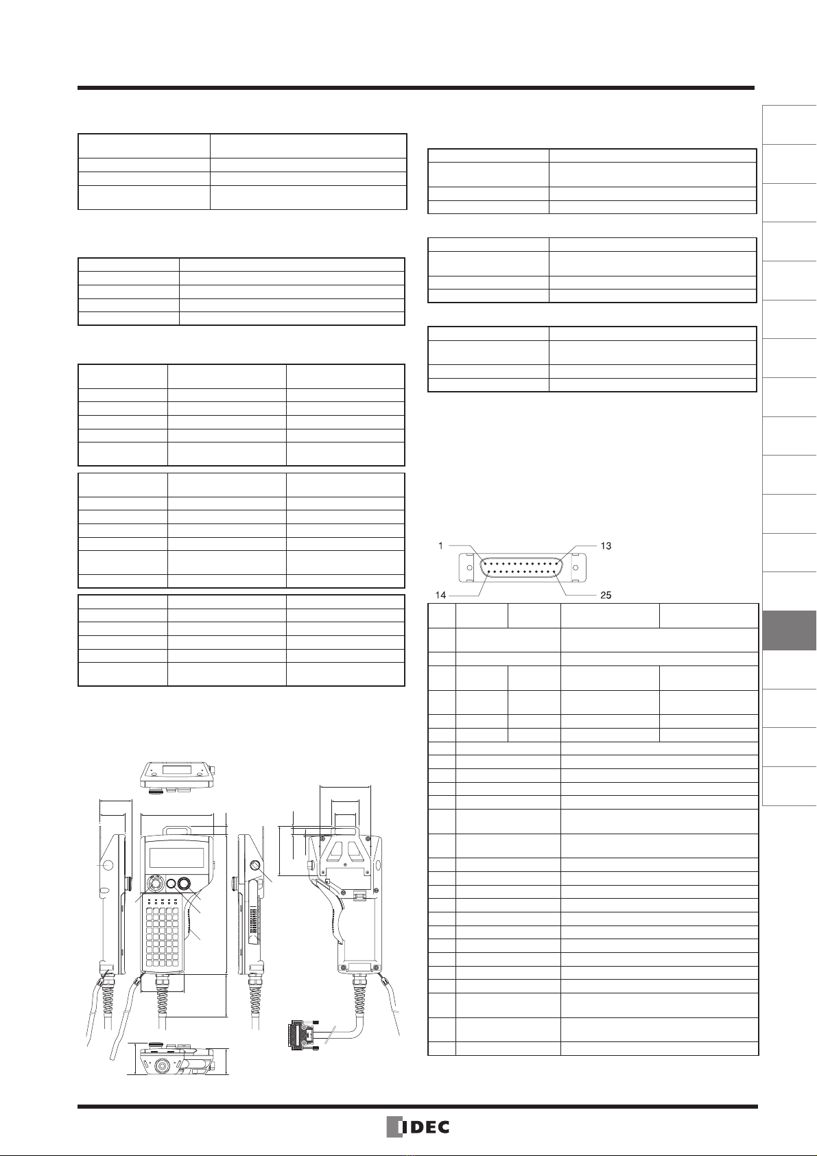
Dimensions
92.6
255
90
46.7
C2
AB2
B1
E
58.3 51.0
38.0
11.5 3.5
1.5
133
All dimensions in mm.
80
46.7
58.3
15
89.8
C1
•
•
Interface Specifications
RS232C
Electrical Characteristics EIA RS232C compliant
Transmission Spee d 38400, 19200, 9600, 4800, 2400, 1200, 600,
300 bps
Synchronization Asynchronous
Communication Method Full duplex or half duplex
RS485
Electrical Characteristics EIA RS485 compliant
Transmission Spee d 38400, 19200, 9600, 4800, 2400, 1200, 600,
300 bps
Synchronization Asynchronous
Communication Method Half duplex
RS422
Electrical Characteristics EIA RS422 compliant
Transmission Spee d 38400, 19200, 9600, 4800, 2400, 1200, 600,
300 bps
Synchronization Asynchronous
Communication Method Full duplex
Note 1:
The HG1T is only available with RS232C/422 interface or
RS232C/485 interface, not available with RS422/485 interface.
RS232C, RS422, and RS485 cannot be used simultaneously.
Note 2: Precaution for communication conditions
Select communication specifications, such as transmission speed,
synchronization system, and communication method.
When a substantially high transmission rate is selected, performance
of the LCD indicator and other response are slower and the data can-
not be received correctly. Specify a proper transmission rate suited to
the application.
Connector Pin Assignment and Functions
D-sub 25-pin connector (plug)
(17JE-23250-02 made by DDK)
RS
232C/422
RS
232C/485 RS232C/422 RS232C/485
Pin
No. Name Function
1 FG Frame ground
2 RD2− TDB RS422
Receive data−
RS485
Communication data B
3 RD2+ TDA RS422
Receive data+
RS485
Communication data A
4 SD2− NC RS422 Send data− Unused
5 SD2+ NC RS422 Send data+ Unused
6 SG Communication signal ground
7 DR (CTS) RS232C communication control input
8 ER (RTS) RS232C communication control output
9 E_NO1 E enabling switch contact 1 (NO)
10 E_C1 E enabling switch contact 1 (COM)
11 A _ N C11 A emergency stop switch contact 1
terminal 1 (NC)
12 A_NC12 A emergency stop switch contact 1
terminal 2 (NC)
13 24V DC (–) Power supply 24V DC (–)
14 RD1 RS232C Receive data
15 SD1 RS232C Send data
16 B1_NO (Note) B1 illuminated pushbutton NO contact
17 B2_ NO (Note) B2 illuminated pushbutton NO contact
18 C1_NO (Note) C1 selector switch NO contact
19 C1_NC (Note) C1 selector switch NC contact
20 SG Communication signal ground
21 E_NO2 E enabling switch contact 2 (NO)
22 E_C2 E enabling switch contact 2 (COM)
23 A_NC21 A emergency stop switch contact 2
terminal 1 (NC)
24 A_NC22 A emergency stop switch contact 2
terminal 2 (NC)
25 24V DC (+) Power supply 24V DC (+)
Note: B1, B2, and C1 (COM) are connected to the power supply 24V DC (–)
pin inside of the HG1T.
•
•
•
HG1T Small Teaching Pendant
1260
Ordering Information
IDEC tailors HG1T small teaching pendants to your specific requirements. Available options are shown on the specification
sheet below. Please discuss your specifications with IDEC’s sales representatives before ordering. Minimum ordering quan-
tity is 100 per lot.
Customer
Contact Person
Address
Type No.
Applications
Department
TEL
Host communication code: U (RS232C/422), W (RS232C/485)
Cable length code: Specify an integer in meters
When using RS232C: 3 to 10 (3 to 10m), When using RS422 or RS485: 3 to 20 (3 to 20m)
MK∗∗∗∗ shows IDEC control number.
Lot Quantity Annual Quantity
() –
Date:
(Ordering Type No.)
HG1T Specifications Sheet
Please use this sheet for specifications of the HG1T small teaching pendant.
Host
HG1T Sheet 01
HG1T –SB12 H –MK –S
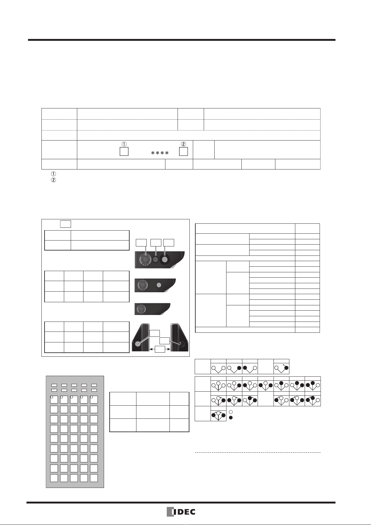
Specify the Mechanical Switches
Determine the arrangement of mechanical switches first. For switch A, select the switch model (button color) and check the box. For switches
B1, B2, C1, and C2, fill in the following columns for Switch Code, Color Code, and Contact with reference to the table on the right.
Switch AMechanical Switch
Arrangement
Front
AB1 B2
Side
Front
C2
C1
•
Switch
Position Switch Model (Button Color)
A®Emergency stop switch (red)
®Stop switch (gray)
Switch B1, B2, C1, C2 (L6 Series
Round)
Front
Switch
Position
Switch
Code
Color
Code
Contact
(1NO, 2NO)
B1
B2
An extended button guard is provided
around B2.
Side
Switch
Position
Switch
Code
Color
Code
Contact
(1NO, 2NO)
C1
C2
Specify the Key Sheet
LED
1
LED
2
LED
3
LED
4
LED
5
LED
6
LED
11
SW41
LED
12
SW42
LED
13
SW43
LED
14
SW44
LED
15
SW45
SW33 SW25 SW17 SW9 SW1
SW34 SW26 SW18 SW10 SW2
SW35 SW27 SW19 SW11 SW3
SW36 SW28 SW20 SW12 SW4
SW37 SW29 SW21 SW13 SW5
SW38 SW30 SW22 SW14 SW6
SW39 SW31 SW23 SW15 SW7
SW40 SW32 SW24 SW16 SW8
LED
7
LED
8
LED
9
LED
10
For the key sheet arrangement, refer to
the figure on the left. Check the indica-
tors and keys to use and write the quanti-
ties in the table below.
No. of LED
Indicators pcs
15 pcs
maximum
No. of Mem-
brane Keys pcs
45 pcs
maximum
No. of Sheet
Colors colors
The LED indicator color is amber.
IDEC will make a key sheet as specified
by a customer. The customer is request-
ed to design the key sheet and provide
the data [File format: ∗.AI (Adobe Il-
lustrator)]. IDEC can also design a key
sheet for customer at an extra charge.
When specifying B1 only
•
Switch Code (other codes are not available)
ø16 A6 Series Control Units
for Switches B1, B2, C1, C2
Switch
Code
Illuminated Pushbutton
(LED, gold contact, 24V DC)
Momentary R11
Maintained R12
Pushbutton Switch
(gold contact)
Momentary R21(L) ∗1
Maintained R22(L) ∗1
Pilot Light (LED, 24V DC) R31
Selector
Switch
(Gold contact)
2-position Maintained R41
Spring return from right R42
3-position
Maintained R43
Spring return from right R44
Spring return from left R45
Spring return two way R46
Key Selector
Switch
(Gold contact)
2-position Maintained R51_ ∗2
Spring return from right R52_ ∗2
3-position
Maintained R53_ ∗2
Spring return from right R54_ ∗2
Spring return from left R55_ ∗2
Spring return two way R56_ ∗2
Dummy Unit R91
∗1: When ordering the "Illuminated lens type" button, add "L" to
the switch code.
∗2: When ordering a key selector switch, add the following key
removable position code to the switch code.
ABCDEGH
LCRLCRLCRLCRLCR
ABC B
LRLRLRLR
LCRLCR
BDG CDH
LCR
D
LCR
LCRLCRLCRLCRLCR
3-pos.
Return
from
Left
3-pos.
Return
from
Right
3-pos.
Return
2-way
2-pos.
Main-
tained
2-pos.
Return
from
Right
3-pos.
Main-
tained
: Key removable position.
: Key retained position.
Color Code (except for selector and key selector switches)
Illuminated Pushbutton and Pilot Light:
A (amber), G (green), R (red), W (white), Y (yellow)
Pushbutton:
B (black), G (green), R (red), S (blue), W (white), Y (yellow)
•
•
When not specifying B1/B2
•
HG1H/HG1T Small Teaching Pendant
Control
Units
Display
Lights
Display
Units
Safety
Products
Terminal
Blocks
Comm.
Terminals
AS-Interface
Relays &
Timers
Sockets
Circuit
Protectors
Power
Supplies
PLCs &
SmartRelay
Operator
Interfaces
Sensors
Control
Stations
Explosion
Protection
References
Flush
Silhouette
1261
Safety Precautions
All products are manufactured under IDEC’s rigorous quality con-
trol system, but users must add a backup or failsafe provision in ap-
plications where heavy damage or personal injury may be caused
in case the HG1H/HG1T should fail.
In this catalog, safety precautions are categorized in order of im-
portance to Warning and Caution:
!Warning signifies a hazard that could result in
personal injury or death in the case of improper
handling.
!Caution signifies a hazard that could result in personal
injury or physical damage in
the case of improper handling.
!Warnings
The unit uses an LCD as a display device. The liquid inside the
LCD is harmful to the skin. If the LCD is broken and the liquid gets
on your skin or clothes, wash the liquid off using soap, and consult
a doctor immediately.
Emergency stop circuits must be configured outside the HG1H/
HG1T by using its emergency stop switch.
Connect the equipped emergency stop switch and enabling
switches to the HG1H/HG1T so that they work in the stop cat-
egory "0" or "1" in accordance with EN60204-1.
The D-sub connector provided with the HG1H/HG1T cable is not
a water or dust-proof type. If you need a water and/or dust-proof
connector, apply a waterproofing treatment to the inlet of cable
connector or replace it with a D-sub connector that is waterproof.
When using the HG1H/HG1T, make sure to securely place your
finger on the enabling switch.
!Caution
Use of the HG1H/HG1T at high temperature and humidity, with
condensation, corrosive gas, excessive vibration, and/or shocks
may cause electric shock, fire, and/or malfunction.
Do not drop the unit when handling or during transportation.
It may cause failure and/or breakage of the unit.
Connect the unit to a power source with a suitable rating. Improp-
er connection may cause a fire.
For wiring, select a suitable wire for the applied current and volt-
age.
Fully check for safety before starting or stopping. Improper opera-
tion may cause damage to the machine and/or accidents.
Do not disassemble, modify, or alter the unit.
Dispose of the HG1H/HG1T unit as industrial waste.
•
•
•
•
•
•
•
•
•
•
•
•
Instructions
Installation environment
In consideration of the product performance and safety, avoid in-
stalling the unit in the following locations:
Where there is a high level of dust, salt air, or iron particles
Where oil or chemical splashes occur
Where direct sunlight falls on the unit
Where a corrosive gas or flammable gas exists
Where the HG1H/HG1T unit is subjected to vibration or shock
Where condensation occurs due to rapid temperature change
Where high-voltage devices or arc-generating equipment (such
as electromagnetic switches, no-fuse breakers, etc.) are located
nearby.
Operating environment
Take the following points into consideration when installing the
HG1H/HG1T on a wall.
Install the HG1H/HG1T so that it will not be exposed to heat
generated by other equipment.
If you plan not to operate the unit using your hands, mount it on a
wall or a stand. For wall mounting, use the mounting bracket on
the back of the HG1T. For the HG1H, use the optional wall mount
bracket (Type No.: HG9Z-HK1).
Do not apply direct force to the D-sub connector.
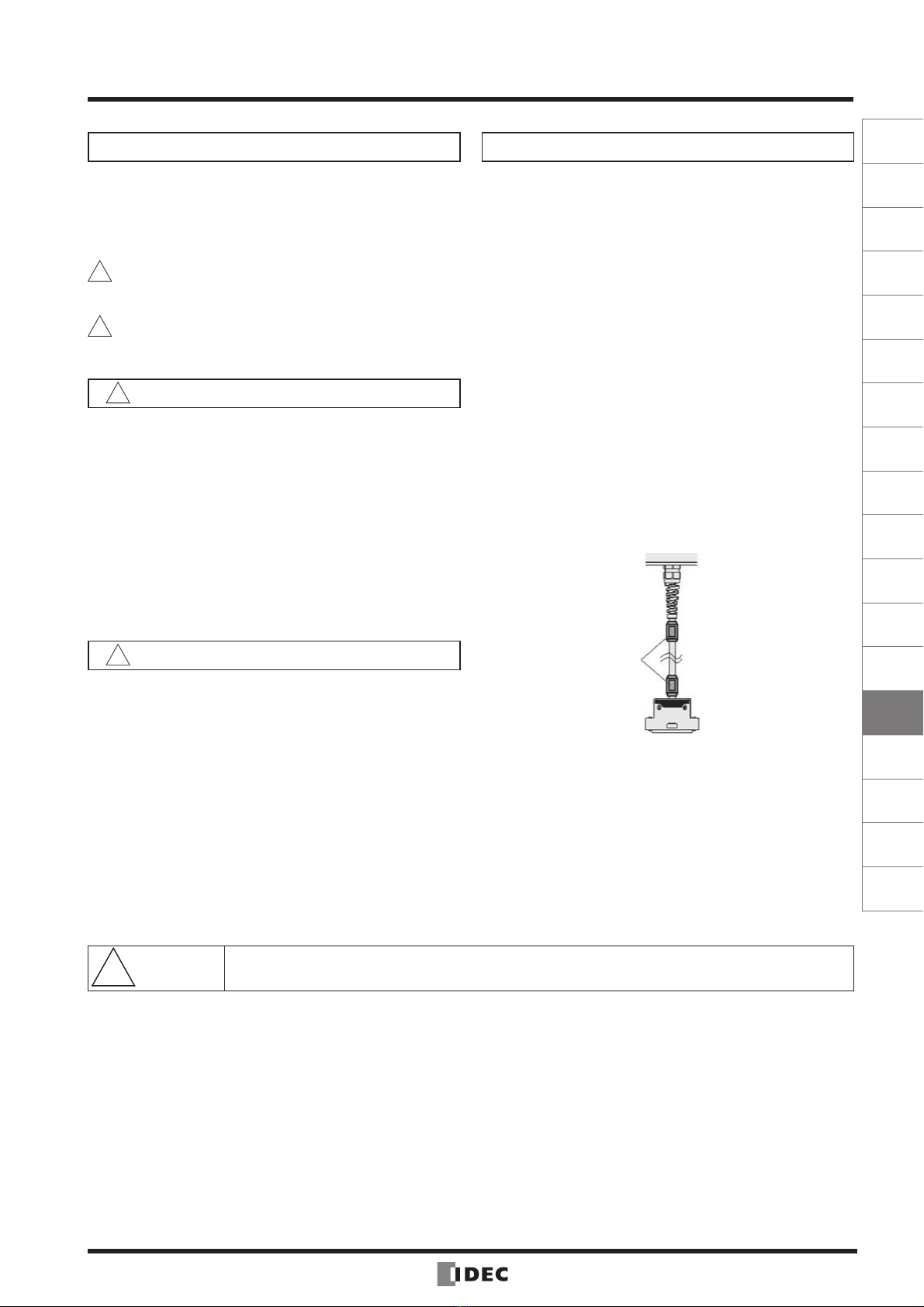
Installation of ferrite cores
When using the HG1T in environments where it is subjected to
a lot of noise, it is recommended that ferrite cores be attached
(ZCAT2436-1330: TDK Corporation, or equivalent) to either or
both ends of the cable.
Ferrite core
•
•
•
•
•
•
•
•
•
•
•
•
•
!Safety
Precautions
Read safety precautions and operating instructions described in the instruction or operation manual and be
sure to use the product properly.
•


