Idex Corken FD151 Installation instructions manual

Warning: (1) Periodic inspection and maintenance of Corken products is essential. (2) Inspection, maintenance and installation of Corken products must be made only
by experienced, trained and qualified personnel. (3) Maintenance, use and installation of Corken products must comply with Corken instructions, applicable laws and
safety standards (such as NFPA Pamphlet 58 for LP-Gas and ANSI K61. 1-1972 for Anhydrous Ammonia). (4) Transfer of toxic, dangerous, flammable or explosive
substances using Corken products is at user’s risk and equipment should be operated only by qualified personnel according to applicable laws and safety standards.
IE103
IMPORTANT
INSTRUCTIONS
FD151 GAS COMPRESSOR


TABLE OF CONTENTS
CHAPTER ONE:HOW YOUR CORKEN COMPRESSOR WORKS . . . . . . . . . . . . . . . . . . . . . . . . . . . . . 4
1.1 Why Corken Compressors are Special. . . . . . . . . . . . . . . . . . . . . . . . . . . . . . . . . . . . . . . . . . . . . . 4
1.2 Running Gear . . . . . . . . . . . . . . . . . . . . . . . . . . . . . . . . . . . . . . . . . . . . . . . . . . . . . . . . . . . . . . . . . 5
1.3 Piston Rod Packing / Distance Pieces . . . . . . . . . . . . . . . . . . . . . . . . . . . . . . . . . . . . . . . . . . . . . . 5
1.4 Piston / Piston Rings. . . . . . . . . . . . . . . . . . . . . . . . . . . . . . . . . . . . . . . . . . . . . . . . . . . . . . . . . . . . 6
1.5 Valves . . . . . . . . . . . . . . . . . . . . . . . . . . . . . . . . . . . . . . . . . . . . . . . . . . . . . . . . . . . . . . . . . . . . . . . 6
1.6 Cooling . . . . . . . . . . . . . . . . . . . . . . . . . . . . . . . . . . . . . . . . . . . . . . . . . . . . . . . . . . . . . . . . . . . . . . 6
1.7 Suction Valve Unloaders . . . . . . . . . . . . . . . . . . . . . . . . . . . . . . . . . . . . . . . . . . . . . . . . . . . . . . . . . 6
CHAPTER TWO:INSTALLING YOUR CORKEN COMPRESSOR . . . . . . . . . . . . . . . . . . . . . . . . . . . . . . 8
2.1 Location. . . . . . . . . . . . . . . . . . . . . . . . . . . . . . . . . . . . . . . . . . . . . . . . . . . . . . . . . . . . . . . . . . . . . . 8
2.2 Foundation . . . . . . . . . . . . . . . . . . . . . . . . . . . . . . . . . . . . . . . . . . . . . . . . . . . . . . . . . . . . . . . . . . . 8
2.3 Piping . . . . . . . . . . . . . . . . . . . . . . . . . . . . . . . . . . . . . . . . . . . . . . . . . . . . . . . . . . . . . . . . . . . . . . . 8
2.4 Liquid Traps. . . . . . . . . . . . . . . . . . . . . . . . . . . . . . . . . . . . . . . . . . . . . . . . . . . . . . . . . . . . . . . . . . . 8
2.5 Driver Installation / Flywheels . . . . . . . . . . . . . . . . . . . . . . . . . . . . . . . . . . . . . . . . . . . . . . . . . . . . 10
2.6 Crankcase Lubrication. . . . . . . . . . . . . . . . . . . . . . . . . . . . . . . . . . . . . . . . . . . . . . . . . . . . . . . . . . 11
2.7 Purging and Draining of Distance Piece . . . . . . . . . . . . . . . . . . . . . . . . . . . . . . . . . . . . . . . . . . . . 12
2.8 Relief Valves . . . . . . . . . . . . . . . . . . . . . . . . . . . . . . . . . . . . . . . . . . . . . . . . . . . . . . . . . . . . . . . . . 13
CHAPTER THREE:START UP OF YOUR CORKEN COMPRESSOR . . . . . . . . . . . . . . . . . . . . . . . . . . 14
3.1 Inspection After Extended Storage . . . . . . . . . . . . . . . . . . . . . . . . . . . . . . . . . . . . . . . . . . . . . . . . 14
3.2 Flywheel and V-belt Alignment . . . . . . . . . . . . . . . . . . . . . . . . . . . . . . . . . . . . . . . . . . . . . . . . . . . 14
3.3 Crankcase Oil Pressure Adjustment . . . . . . . . . . . . . . . . . . . . . . . . . . . . . . . . . . . . . . . . . . . . . . . 15
3.4 Adjustment of Mechanical Unloader Controls . . . . . . . . . . . . . . . . . . . . . . . . . . . . . . . . . . . . . . . . 15
3.5 Startup Check List. . . . . . . . . . . . . . . . . . . . . . . . . . . . . . . . . . . . . . . . . . . . . . . . . . . . . . . . . . . . . 16
CHAPTER FOUR:ROUTINE MAINTENANCE CHART. . . . . . . . . . . . . . . . . . . . . . . . . . . . . . . . . . . . . . 17
CHAPTER FIVE: ROUTINE SERVICE AND REPAIR PROCEDURES. . . . . . . . . . . . . . . . . . . . . . . . . . 18
5.1 Valves . . . . . . . . . . . . . . . . . . . . . . . . . . . . . . . . . . . . . . . . . . . . . . . . . . . . . . . . . . . . . . . . . . . . . . 18
5.2 Cylinder and Head . . . . . . . . . . . . . . . . . . . . . . . . . . . . . . . . . . . . . . . . . . . . . . . . . . . . . . . . . . . . 19
5.3 Piston Rings and Piston Ring Expanders . . . . . . . . . . . . . . . . . . . . . . . . . . . . . . . . . . . . . . . . . . . 19
5.4 Piston Replacement . . . . . . . . . . . . . . . . . . . . . . . . . . . . . . . . . . . . . . . . . . . . . . . . . . . . . . . . . . . 19
5.5 Piston Rod Packing Adjustment . . . . . . . . . . . . . . . . . . . . . . . . . . . . . . . . . . . . . . . . . . . . . . . . . . 20
5.6 Bearing Replacement . . . . . . . . . . . . . . . . . . . . . . . . . . . . . . . . . . . . . . . . . . . . . . . . . . . . . . . . . . 20
5.6.1 Wrist Pin Bushing Replacement. . . . . . . . . . . . . . . . . . . . . . . . . . . . . . . . . . . . . . . . . . . . . . . . . 21
5.6.2 Connecting Rod Bearings . . . . . . . . . . . . . . . . . . . . . . . . . . . . . . . . . . . . . . . . . . . . . . . . . . . . . 21
5.6.3 Roller Bearings. . . . . . . . . . . . . . . . . . . . . . . . . . . . . . . . . . . . . . . . . . . . . . . . . . . . . . . . . . . . . . 21
5.7 Oil Pump Inspection . . . . . . . . . . . . . . . . . . . . . . . . . . . . . . . . . . . . . . . . . . . . . . . . . . . . . . . . . . . 22
CHAPTER SIX: EXTENDED STORAGE PROCEDURES. . . . . . . . . . . . . . . . . . . . . . . . . . . . . . . . . . . . 23
APPENDIX
A. Material Specifications . . . . . . . . . . . . . . . . . . . . . . . . . . . . . . . . . . . . . . . . . . . . . . . . . . . . . . . . . . 24
B. Mechanical Specifications and Bolt Torque Valves . . . . . . . . . . . . . . . . . . . . . . . . . . . . . . . . . . . . 25
C. Clearance and Dimensions, Purging and Draining of Distance Piece . . . . . . . . . . . . . . . . . . . . . . 26
D. Piston Details . . . . . . . . . . . . . . . . . . . . . . . . . . . . . . . . . . . . . . . . . . . . . . . . . . . . . . . . . . . . . . . . . 27
E. Distance Piece / Packing Details . . . . . . . . . . . . . . . . . . . . . . . . . . . . . . . . . . . . . . . . . . . . . . . . . . 28
F. Head / Valve Details . . . . . . . . . . . . . . . . . . . . . . . . . . . . . . . . . . . . . . . . . . . . . . . . . . . . . . . . . . . . 29
G. Connecting Rod and Crosshead Assembly Details . . . . . . . . . . . . . . . . . . . . . . . . . . . . . . . . . . . . 31
H. Crankcase Details . . . . . . . . . . . . . . . . . . . . . . . . . . . . . . . . . . . . . . . . . . . . . . . . . . . . . . . . . . . . . 32
I. Parts List FD151 . . . . . . . . . . . . . . . . . . . . . . . . . . . . . . . . . . . . . . . . . . . . . . . . . . . . . . . . . . . . . . . 34
GENERAL
J. Compressor Troubleshooting . . . . . . . . . . . . . . . . . . . . . . . . . . . . . . . . . . . . . . . . . . . . . . . . . . . . . 36
K. Compressor Startup Log Sheet . . . . . . . . . . . . . . . . . . . . . . . . . . . . . . . . . . . . . . . . . . . . . . . . . . . 37

4 FD151 Gas Compressor
Corken industrial gas compressors are unique
among compressors their size. Unlike ordinary
lubricated gas compressors, Corken compressors
completely isolate the pressurized gas in the
compression chamber from the crankcase. While
piston rings seal the piston tightly enough for it to do
compression work, they do not provide enough
sealing to isolate the compression chamber from the
crankcase. To further seal the compression chamber,
a crosshead/piston rod design with seals around the
piston rod is required (see Figure 1.1A).
By utilizing specialized piston-rod sealing systems,
Corken compressors can compress pressurized,
flammable and toxic gases. It is also used to
compress harmless gases where oil-free
compression or elevated suction pressures are
required. With a numerous selection of design
options available, Corken offers the most versatile
line of small gas compressors in the world.
1.1 WHY CORKEN COMPRESSORS ARE SPECIAL
Unloader Assembly
(Optional)
Piston Assemblies
Packing set (Upper)
Suction Valve Assembly
Oil Deflector Ring
Packing Set (Lower)
Wrist Pin
Connecting Rod
Oil Level Bayonet
Main Bearing
Inspection Plate
(Model and
Serial Number)
Crosshead and
Piston Rod Assembly
Oil Pressure
Adjustment Screw
Oil Pump
Oil Pressure Gauge
Head
Discharge Valve
Assembly
Outlet
Cylinder
Intercooler
(2-Stage Only)
Distance Piece
Crosshead Guide
Crankcase
Flywheel
Figure 1.1A
Cross Section of a Typical Corken Oil-Free Vertical Compressor
CHAPTER ONE
HOW YOUR COMPRESSOR WORKS

FD151 Gas Compressor 5
1.2 RUNNING GEAR
Corken gas compressors are mounted on sturdy oil-
lubricated crankcases. Crankshafts are supported by
heavy-duty roller bearings. The connecting rods ride
the crankshaft on journal bearings. All compressor
crankcases are pressure lubricated. An automatically
reversible gear-type oil pump circulates oil through
passages drilled in the crankshaft and connecting
rod to lubricate journal bearings and wrist pins (see
Figure 1.2A). Sturdy iron crossheads transmit
reciprocating motion to the piston.
Corken's automatically reversible oil pump design
allows the machine to function smoothly in either
direction of rotation. A replaceable 10-micron spin-on
oil filter ensures long life.
1.3 PISTON ROD PACKING / DISTANCE
PIECES
Piston rod packing is used to seal gas in the
compression chamber and prevent seepage of oil out
of the crankcase into the compressor cylinder. The
packing consists of several PTFE V-rings
sandwiched between a male and female ring (see
Figure 1.3A). The packing rings are spring loaded to
allow a small amount of “float” to alleviate cyclic
stresses, reduce wear, and assure a positive seal.
WRIST PIN BUSHING
JOURNAL BEARING
CRANKSHAFT
OIL PUMP
Pressure Lubrication System
Figure 1.2A

6 FD151 Gas Compressor
Corken manufactures compressors with one, two,
or three packing sets. Standard-style units contain
one packing set. For completely oil-free
compression, two packing sets are used (see
Figure 1.3A). Oil-free compressors are designated
by the prefix “D". Oil that seeps past the first
packing set is prevented from reaching the second
by an oil deflector ring. Three packing sets and two
distance pieces are available on special machines
for compressing highly corrosive gases. Units with
three packing sets are designated by the prefix "T".
The construction of the "D"- and "T"-style units
ensures that no part of the rod which travels into
the crankcase enters the cylinder.
The distance pieces may be vented or purged with
an inert gas. The orientation of the packing varies
with the application. See Sec. 2.10 and Appendix F
for more details.
1.4 PISTON/PISTON RINGS
Corken compressors use iron pistons that are
locked to the piston rod. The standard piston ring
material is a glass-filled PTFE polymer specially
formulated for non-lubricated service. Piston ring
expanders are placed behind the rings to insure that
the piston rings seal against the cylinder wall (see
Figure 1.4A).
1.5 VALVES
The typical Corken compressor valve consists of a
seat, bumper, spring and valve disk, as shown in
Figure 1.5A. Special heat-treated alloys are utilized
to prolong the life of the valve in punishing non-
lubricated services. The valve opens whenever the
pressure on the seat side exceeds the pressure on
the spring side. The discharge valve is an inverted
version of the suction valve.
1.6 COOLING
Your Corken compressor model FD151 is air-cooled.
It is important to maintain good air flow around your
compressor. Keep this in mind as you select the
location where the compressor will operate.
1.7 SUCTION VALVE UNLOADERS
(OPTIONAL)
Some Corken compressors are equipped with
suction valve Unloaders. Check your model number
against Appendix A to determine the valve/unloader
Gas Pressure Forces
Ring Against Wall
Piston Ring
Groove
Piston Ring
Expander
Piston Ring
Cylinder Wall
Figure 1.4A
Gas flows down from cylinder
Figure 1.5A
Figure 1.3A
Suction Valve
Spec 4, 7, 78, 8, 9
Discharge
Valve
Suction
Valve Seat
Suction
Valve Plate
Suction
Spring
Suction Valve
Bumper
Discharge
Valve Bumper
Discharge
Valve Spring
Discharge
Valve Plate
Discharge
Valve Seat
Distance Piece (‘D’ Style)
V-Ring
Packing
Deflector
Ring
Packing
Spring
Packing
Adjustment
Nut

FD151 Gas Compressor 7
arrangement for your machine. If the valve/unloader
number for your machine is 3 or 4, proceed to
chapter 2 (your machine has no unloaders).
The suction valve unloader is a small piston and
cylinder assembly that is installed over the suction
valve (see Figure 1.1A). The small piston is connected
to a rod that extends into the suction valve assembly.
The unloader piston is depressed when gas
pressurized to 40 psi or more above suction pressure
is injected into the unloader cylinder.
In the depressed position, the piston pushes the rod
against the suction valve disk to hold the suction
valve in an open position. In this position, no
compression will occur, even though the pistons are
still moving up and down.
The unloaders are controlled by devices which
control the flow of gas into and out of the unloader
cylinder. The different types of unloader controls may
be summarized as follows:
SPECIFICATION 9 - When the gas being
compressed cannot be vented to the atmosphere,
electronic controls should be used as shown in
Figure 1.7D. The use of an optional three-way
solenoid valve allows gas from the unloader to be
vented back to the compressor suction instead of to
atmosphere. A time delay may be used to achieve
loadless start and a pressure switch may be used
to achieve constant-speed unloading.
Specification 9
Figure 1.7D
Unloaded Loaded

8 FD151 Gas Compressor
2.1 LOCATION
Corken compressors are designed and
manufactured for outdoor duty. For applications in
which the compressor will be subjected to extreme
conditions for extended periods, such as hot boiler
rooms, corrosive environments, arctic or desert
conditions, etc., consult Corken. Check local safety
regulations and building codes to assure installation
will meet local safety standards.
Corken recommends that machines compressing toxic
or flammable gases be placed outdoors. If such units
are placed indoors, make sure the area is well
ventilated. Vent the distance piece to the outdoors or
purge the distance piece with an inert gas and vent to
a safe disposal area.
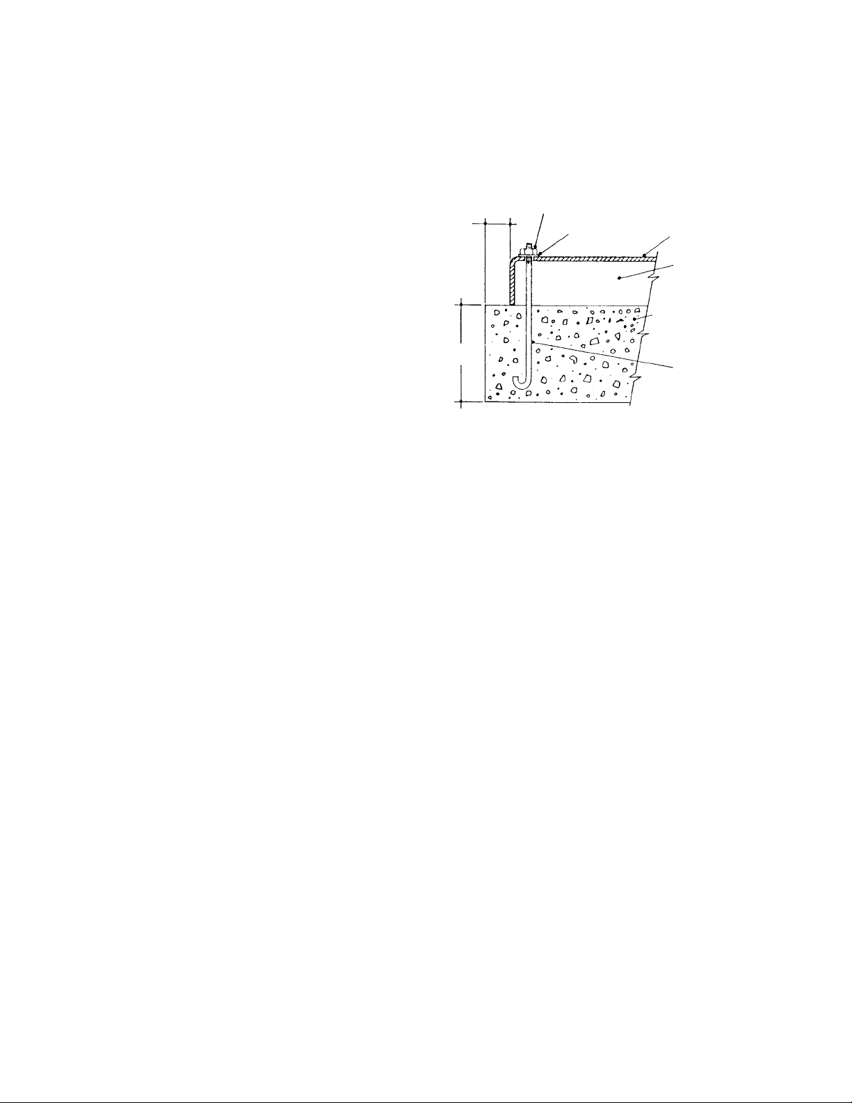
2.2 FOUNDATION
Proper foundations are essential for a smooth running
compression system. Corken recommends the
compressor be attached to a concrete slab at least 8"
thick, with a 2" skirt around the circumference of the
baseplate. The baseplate should be securely
anchored into the foundation by 1/2"diameter "J" bolts
12" long. The total mass of the foundation should be
approximately twice the weight of the compressor
system (compressor, baseplate, motor, etc.). After
leveling and bolting down the baseplate, the volume
beneath the channel must be grouted iron baseplate
to prevent flexing of the top portion of the "J" bolt that
extends beyond the foundation. The grout also
improves the dampening capabilities of the
foundation by creating a solid interface between the
compressor and foundation.
On models mounted on a longer baseplate a hole
can be cut in the baseplate for filling the middle
section of the channel-iron base with grout. See
additional foundation design aids in appendix H.
2.3 PIPING
Proper piping design and installation is as important
as the foundation is for smooth operation of the
compressor. Improper piping installation will result
in undesirable transmission of compressor vibration
to the piping.
DO NOT SUPPORT PIPING WITH THE
COMPRESSOR.
Unsupported piping is the most frequent cause of
pipe vibration. The best method to assure
transmission of vibration from the compressor to the
piping is minimized by using flexible connectors (see
Figure 2.3A).
Pipe must be adequately sized to prevent excessive
pressure drop between the suction source and the
compressor, as well as between the compressor and
the final discharge point. In most cases, piping should
be at least the same diameter as the suction nozzle
on the compressor.
Care must be taken if a restriction device such as a
valve, pressure regulator, or back-check valve is to
be installed in the compressor's suction line. The
suction line volume between the restrictive device
and the compressor suction nozzle must be at least
ten times the swept cylinder volume.
Piping must be installed to prevent condensate from
draining into the compressor. This is especially
important on applications where gas is being handled
at or near its saturation point.
Figure 2.2A
2” Min.
All Sides
8” Min.
Hex Nut
Washer Compressor
Baseplate
Grout Beneath
Base
Concrete Foundation
With Reinforcements
Should be Used on
All Models
1/2” “J” Bolts
12” Long
Recommended Foundation Details
for Corken Compressors
Note:
Locate “J” Bolts Per
Compressor Outline
Dimension Drawings
CHAPTER TWO
INSTALLING YOUR CORKEN COMPRESSOR

FD151 Gas Compressor 9
On oil-field gas compressors, "heavy ends" such as
pentane, hexane, heptane, etc., may accumulate
beneath the piston over a period of time. For this
reason, lubricated compressors are equipped with a
drain cock to allow draining of the volume beneath the
piston before start-up.
2.4 LIQUID TRAPS
Compressors are designed to pressurize gas, not to
pump liquids. Since liquids are incompressible, the
entry of even a small amount of liquid into the
compressor can result in a highly undesirable
phenomenon called "liquid slugging”. Since the
compressor attempts to compress a non-
compressible fluid in this situation, high-impact
stresses are created that will result in serious
damage to the compressor.
On applications where the presence of entrained
liquids in the suction gas is a possibility, a liquid
trap must be used to prevent the entry of liquid into
the compressor.
Corken offers three types of liquid traps for removal
of entrained liquids. The simplest is a mechanical
float trap (see Figure 2.4A). As the liquid enters the
trap, the gas velocity is greatly reduced, allowing
the entrained liquid to drop out. If the liquid level
Figure 2.3A
Figure 2.4A
Mechanical Trap
Rigid Piping
Flexible Connectors
Rigid Piping
Support Support
Outlet
Vacuum Breaker
Valve
Ball Float
Drain Valve
Inlet
Piping Details

10 FD151 Gas Compressor
Figure 2.4B Figure 2.4C
Automatic Liquid Trap ASME Automatic Trap
rises above the inlet, the float will plug the
compressor suction. The compressor creates a
vacuum in the inlet piping and continues to operate
until it is manually shut down by the operator.
Before restarting the compressor, drain the trap
and open the vacuum-breaker valve to allow the
float to drop back to the bottom of its holder. This
type of trap is only appropriate for use where the
compressor is kept under fairly close observation
by the operator.
For continuous-duty operation applications such as
those found in the chemical industry, an automatic
trap should be used (see Figure 2.4B). The automatic
trap replaces the mechanical float with electrical float
switches. If the liquid level should rise too high, the
level switch will open and disconnect the power to
the motor starter, stopping the compressor. This
design ensures the machine will be protected even
when it is not under close observation.
Corken's most sophisticated trap provides the most
thorough liquid separation (see Figure 2.4C). This
trap is larger and is ASME-code stamped. It contains
two level switches, one for alarm and one for
shutdown. In some cases, the alarm switch can
activate a dump valve (not included with trap) or
sound an alarm. A drain valve is included to manually
drain the trap. This trap also contains a mist pad (a
mesh of interwoven wire to disentrain fine-liquid
mists). The ASME-code trap is an available option on
most models.
Outlet
Liquid Level
Float Switch
Baffle
Inlet
Drain Valve
Drain
Drain
Liquid-Level
Alarm Switch
High-Liquid-Level
Shutdown Switch
Inlet
Mist Pad
Pressure Gauge
Outlet
Relief Valve

FD151 Gas Compressor 11
A typical wiring diagram for the liquid level switch is
shown in Figure 2.4D. The switches can be set for
either normally open or normally closed operation.
Some level switches vary in operation. follow
manufacturers instructions for operating mode you
have selected.
NOTE: The level switch MUST be removed from
the trap before grounding any welding devices
to the trap or associated piping! Failure to do so
will damage the switch contacts.
If your compressor is equipped with a liquid trap of
other than Corken manufacture, make sure it is of a
size adequate to thoroughly remove any liquid
entrained in the suction stream.
2.5 DRIVER INSTALLATION / FLYWHEELS
Corken vertical compressors may be driven either by
electric motors or combustion engine (gasoline,
diesel, natural gas, etc.). Corken compressors are
usually V-belt driven, but they are suitable for direct-
drive applications as well. Direct-drive applications
require an extended crankshaft to allow the
attachment of a rigid metal coupling. NOTE:
FLEXIBLE COUPLINGS ARE NOT SUITABLE FOR
RECIPROCATING COMPRESSORS. NEVER
OPERATE A RECIPROCATING COMPRESSOR
WITHOUT A FLYWHEEL.
Select drivers so that the compressor operates
between 350 to 825 RPM. Do not operate the unit
without the flywheel; severe torsional imbalances will
result that could cause vibration and high
horsepower requirement. The flywheel should never
be replaced by another pulley unless it has a higher
wk2value than the flywheel.
A humid climate can cause problems, particularly in
explosion-proof motors. The normal breathing of the
motor, as well as alternating between being warm
when running and cool when stopped, can draw
moist air into the motor. This moist air will condense,
and may eventually add enough water inside the
motor to cause it to fail. To prevent this, make a
practice of running the motor at least once a week on
a bright, dry day for an hour or so without the V-belts.
In this period of time, the motor will heat up and
vaporize the condensed moisture, driving it from the
motor. No motor manufacturer will guarantee
explosion-proof or totally enclosed (TEFC) motors
against damage from moisture. For installation with
engine drivers, thoroughly review instructions from
the engine manufacturer to assure the unit is
properly installed.
ACCEPTABLE CRANKCASE OIL PRODUCTS
FOR CORKEN COMPRESSORS
CONSTANT WEIGHT - NON-DETERGENT - R&O INHIBITED
OIL PRODUCT ISO VI SAE AMBIENT TEMP
Exxon®
TERESSTIC 100 95 30 65° - 100° F
68 95 20+ 45° - 70° F
46 95 20 35° - 50° F
Mobil®
RARUS 427 Reciprocating 100 95 30 65° - 100° F
Compressor Oil
DTE Oil Heavy Medium 64 95 20+ 45° - 100° F
Dectol R&O Oil 44 95 20 35° - 50° F
Conoco®
Dectol R&O Oil 100 98 30 35° - 50° F
68 97 20+ 45° - 70° F
46 99 20 35° - 50° F
Texaco®
Regal R&O Oil 100 92 30 65° - 100° F
68 97 20+ 45° - 70° F
46 102 20 35° - 50° F
Sun®
SunVis 900 Oil 100 100 30 65° - 100° F
68 100 20+ 45° - 70° F
46 100 20 35° - 50° F
Figure 2.6A
Compressor Model Approximate Capacity
Quarts Liters
FD151 1.5 1.4
Figure 2.6B
Figure 2.4D
Wiring Diagram
L1
Stop Start
Level Switch
#2462 OLR
M
M
Protective Thyrector
110VAC CORKEN #3848 or G.E. #V150-LA1
220VAC CORKEN #3849 or G.E. #V300-LA2
L2

12 FD151 Gas Compressor
2.6 CRANKCASE LUBRICATION
Non-detergent oil is recommended for Corken
compressors. Detergent oils tend to keep wear
particles and debris suspended in the oil, whereas
non-detergent oils let them settle to the bottom of the
crankcase. When non-detergent oils are not
available, detergent oils usually may be substituted
successfully, although compressors handling
ammonia, amine, or imine gases are notable
exceptions. These gases react with the detergent
and cause the crankcase oil to become corrosive and
contaminated. Figures 2.6A & B show recommended
oil viscosities and crankcase capacities.
New or rebuilt units should be filled with oil
through the opening behind the compressor
nameplate. This provides excellent lubrication for
the crossheads on initial startup (see Figure 2.6C).
Synthetic lubricants are generally not necessary.
Please consult the factory if you are considering the
use of a synthetic oil.
2.7 PURGING AND DRAINING OF
DISTANCE PIECES
The key to leakage control and oil-free operation of
Corken compressors is the distance piece. Distance
pieces are equipped with tapped holes to purge,
vent and drain. Proper connections to and from
these tapped holes are essential for optimum
compressor performance.
Since some oil will pass the bottom packing set,
regular draining of the distance piece is essential
to maintain oil-free operation (See Figure 2.7).
Corken recommends checking and draining the
distance piece once a week for units in
continuous-duty operation. Installing a drain cock
to the distance piece drain will help simplify draining
of the distance piece.
Compressors with "A"-Style packing arrangements
are shipped with all connections plugged. The
distance piece will pressurize in this type application.
Corrosive gases should be prevented from
entering the crankcase, since even minute
amounts of leakage into the crankcase can
seriously contaminate the crankcase oil. To
prevent this contamination, the distance piece
may be purged, buffered, or both purged and
buffered by a dry, clean, non-corrosive gas like air
or nitrogen.
Figure 2.7
Flywheel
Side
Figure 2.6C
Remove this plug periodically to
drain distance piece.
Typical connection points for distance
piece drain, vent or purge lines.
Note: Fill crankcase with oil through this opening

PURGING. Purging without buffering can only be
performed on units with “A”-Style packing
arrangements. Purge gas at a lower pressure than
the suction pressure fed into the distance piece
through the purge connection and discharged from
the vent. Moisture and condensate can be removed
from the distance piece with the purge gas by
opening the vent connection at the bottom of the
distance piece. By purging the distance piece,
leakage into the distance piece is quickly diluted by
the purge gas and swept away. The purge gas should
be vented to a safe release area, flare, or treatment
facility, depending on the gas and local regulations.
PURGE & BUFFER. For applications with vacuum
inlet pressures and/or low operating pressure (200
psig or less), buffering offers advantages over purge-
only systems. For buffered systems, the distance
piece is pressurized ABOVE discharge pressure with
a clean, dry, inert gas (usually dry air or nitrogen). The
top packing set is inverted to point up. For “B” & “E”-
Style packing arrangements, disconnect and plug
lines running to the discharge of the compressor (first
or second stage). Otherwise, the purge gas will tend
to leak into the compression chamber. Purging and
buffering can be accomplished by venting the distance
piece to a safe release area. A backpressure valve
may be used to maintain proper distance piece
pressure.
VENT ONLY. Compressors used for flammable but
non-toxic, non-corrosive gases or for indoor
applications require the distance piece to be vented to
an appropriate release area, flare, or treatment facility.
HIGHLY CORROSIVE GASES. The compressor
should be blocked from the system via valves on
the suction and discharge piping, then purged with
dry inert gas before being shut down. Experience
has proven this significantly lowers possible
corrosion damage to the machine.
2.8 RELIEF VALVES
Any line leading to or from the compressor that can
be blocked by a valve or other restrictive device
must be equipped with a relief valve. The relief
valve should be able to relieve a volume of gas
higher than the piston displacement of the
compressor. Relief valves should be made of
materials compatible with the gas being
compressed. For compressors handling toxic or
flammable gases, the relief valves should be piped
to an area where it is safe to release gas.
FD151 Gas Compressor 13

14 FD151 Gas Compressor
NOTE: Read entire chapter before going to start-
up checklist.
3.1 INSPECTION AFTER EXTENDED
STORAGE
If your compressor has been out of service for a long
period of time, verify that the cylinder bore and valve
areas are free of rust and other debris (see the
maintenance section of this manual for valve and/or
cylinder head removal instructions).
Drain the oil from the crankcase and remove the
nameplate and crankcase inspection plate. Inspect
the running gear for signs of rust and clean or replace
parts as necessary. Replace the crankcase
inspection plate and fill the crankcase with the
appropriate lubricant. Squirt oil on the cross-heads
and rotate the crank by hand to ensure that all
bearing surfaces are coated with oil.
Rotate the unit manually to ensure that the running
gear functions properly. Replace the nameplate and
proceed with start-up.
3.2 FLYWHEEL AND V-BELT ALIGNMENT
Before working on the drive assembly, be sure
that the electric power is disconnected.When
mounting new belts, always make sure the driver and
compressor are close enough together to avoid
forcing the belts on.
Normal rotation is counterclockwise, facing the flywheel.
This is important for two-stage units with intercoolers.
Improper belt tension and sheave alignment can
cause vibration, excessive belt wear and premature
bearing failures. Before operating your compressor,
check the alignment of the V-grooves of the
compressor and drive sheaves, visual inspection will
often indicate if the beIts are properly aligned, but use
of a square is the best method.
The flywheel is mounted on the shaft via a split,
tapered bushing and three bolts (Figure 3.2A). These
bolts should be tightened in an even and progressive
manner until torqued as specified below. There must
be a gap between the bushing flange and the sheave
when installation is complete. Always check the
flywheel runout before start-up and readjust if it
exceeds the value listed in Appendix D.
Tighten the belts so that they are taut but not
extremely tight. Consult your V-belt supplier for
specific tension recommendations. Belts that are too
tight may cause premature bearing failure.
Figure 3.2b
Bushing Diameter Bolt Torque
Size In. (cm) ft.-lb. (kg-meter)
SF 4.625 (11.7) 30 (4.1)
E 6.0 (15.2) 60 (8.3)
FLYWHEEL INSTALLATION
Figure 3.2a
CHAPTER THREE
STARTING UP YOUR CORKEN COMPRESSOR
Typically
1/4” to 3/8”
(6.4 MM to 9.5 MM)

FD151 Gas Compressor 15
3.3 CRANKCASE OIL PRESSURE
ADJUSTMENT
Your Corken compressor Model FD151 is
equipped with an automatically reversible
geartype oil pump. Ensure that the pumping
system is primed and the oil pressure is properly
adjusted to assure smooth operation.
Before starting your compressor, check and fill the
compressor crankcase with the proper quantity of
lubricating oil.
To assure critical lubrication of crossheads and
crosshead guide during the initial start-up period:
• Remove inspection plate from crosshead guide.
• Fill crankcase with lubricating oil through the
inspection
plate opening (Figure 2.6C).
• Allow the oil to lubricate the crossheads and guide
as it fills into the crankcase.
• Check crankcase oil level at the oil bayonet. (Re-
install the inspection plate and gasket.)
• Follow any other pre-start-up procedures that may
be necessary in your application.
• Double-check the crankcase oil level.
• Start compressor, observing the crankcase oil
pressure gauge. If oil-pressure gauge does not
register 20 - 30 PSIG after 30 seconds, stop the
unit. Refer to Trouble-Shooting Guide in Appendix
J. Consult the Factory if condition cannot be
corrected. DO NOT continue to run the
compressor without the correct oil pressure.
The oil pressure should be about 20 psi (2.4 Bars)
minimum for normal service. If the discharge
pressure is above 200 psi (14.8 Bars) or if the
compressor is equipped with a hydraulic unloader
(Specification 7 or 78; see Figure 3.4A), the oil
pressure must be maintained at a minimum of 25
psi (2.7 Bars). The oil pressure is regulated by a
spring-loaded relief valve mounted on the bearing
housing opposite the flywheel. As shown in Figure
3.3A, turn the adjusting screw clockwise to increase
the oil pressure, counterclockwise to lower it. Be
sure to loosen the adjusting-screw lock nut before
making any adjustments. Tighten locknut back after
any adjustments.
3.4 ADJUSTMENT OF MECHANICAL
UNLOADER CONTROLS
NOTE: If your compressor is not equipped with
mechanical unloader control (valve/ unloader Spec.
7, 78, and 8; see Appendix A to determine if this
applies to your machine), proceed to Section 3.5. See
Section 1.7 for explanation on how suction valve
unloaders work.
Figure 3.3a
Oil Pressure Adjustment
Oil Level Bayonet
Full
Low
Oil
Pressure
Gauge
Oil
Pump
Cover
Lock Nut
Oil Pressure
Adjusting Screw

16 FD151 Gas Compressor
3.5 STARTUP CHECK LIST
Please verify all of the items on this list before
starting your compressor! Failure to do so may
result in a costly (or dangerous) mistake.
BEFORE STARTING THE COMPRESSOR:
1. Become familiar with the function of all piping
associated with the compressor. Know each line's
use!
2. Verify that actual operating conditions will match
anticipated conditions.
3. Ensure that line pressures are within cylinder-
pressure ratings.
4. Clean out all piping.
5. Check that distance piece vents are tubed or
plugged as desired.
6. Check all mounting shims, cylinder and piping
supports to ensure that no undue twisting forces
exist on the compressor.
7. Verify that strainer elements are in place and
clean.
8. Verify that cylinder bore and valve areas are
clean.
9. Check V-belt tension and alignment. Check drive
alignment on direct-drive units.
10.Rotate unit by hand. Check flywheel for wobble or
play.
11.Check crankcase oil level and all other fluid
levels (lubricator, radiator, oil reservoirs, etc.).
12.Drain all liquid traps, separators, etc.
13.Verify proper electrical supply to motor and panel.
14.Check that all gauges are at zero-level reading.
15.Test piping system for leaks.
16.Purge unit with air before pressurizing with gas.
17.Carefully check for any loose connections or
bolts.
18.Remove all stray objects (rags, tools, etc.) from
vicinity of unit.
19.Verify that all valves are open or closed as
required.
20.Double-check all of the above.
AFTER STARTING THE COMPRESSOR:
1. Verify and note proper oil pressure. Shut down
and correct any problem immediately.
2. Observe noise and vibration levels. Correct
immediately
if excessive.
3. Verify proper compressor speed.
4. Examine entire system for gas, oil or water leaks.
5. Note rotation direction.
6. Check start-up voltage drop, running amperage
and voltage at motor junction box (not at the
starter).
7. Verify proper lube rate (lubed units only).
8. Test each shut-down device and record set points.
9. Test all dump valves, relief valves and unloaders.
10.Check and record all temperatures, pressures
and volumes after 30 minutes and 1 hour.
11.After 2-5 hour of running time, check, retorque all
head bolts, valve hold-down screws, and
baseplate anchor bolts.

FD151 Gas Compressor 17
ITEM TO CHECK First Week Daily Weekly 250 1000 2000 6000
Only Hours Hours Hours Hours
Crankcase oil pressure X
Compressor suction pressure X
Compressor discharge pressure X
Compressor discharge temperature X
Crankcase oil level X
Drain liquid from system accumulation points X
Drain / check distance piece X
Check V-belts for correct tension X
Retorque valve holddown screws X(c) X
Complete preventative maintanence X(d)
Replace valve assemblies X
Replace piston rings X(a)
Replace packing rings X
Change crankcase oil X(b)
Complete Rebuild X(e)
a. Piston ring life varies greatly, depending on application, gas, and operating pressures. Consult factory for additional
recommendations for your specific applications and operating pressures. The initial set of piston rings may wear
faster than replacement rings. Piston ring life tends to get better as the ring material transfers into the cylinder wall
surfaces. On units with coated cylinders it is recommended to replace the initial piston rings after 1,000 hours.
b. Change oil and filter every 250 hours of operation or every 45 days, whichever occurs first.
c. Holddown screws must be checked at least once in the first 200 hours of operation.
d. Includes rings, valves, packing and gaskets.
e. All bearings, crossheads, rings, valves, packing and gaskets.
* Recommended maintenance as suggested above are general guidelines only. Your specific maintenance
requirements may vary depending on the operating conditions and duty cycle.
CHAPTER FOUR
ROUTINE MAINTENANCE CHART

18 FD151 Gas Compressor
5.1 VALVES
CAUTION: Always relieve pressure in the unit
before attempting any repairs.
Low capacity, overheating, noise and vibration are all
indications of possible valve failure. Because valve
problems can manifest themselves in so many
different forms, valve inspection is frequently the best
first step in troubleshooting poor performance.
To remove and inspect valves, begin by
depressurizing and purging (if necessary) the unit.
Next, remove the valve cap or unloader assembly and
then remove the valve holddown screw (see Figure 5.1
A) with the special wrench supplied with the compressor.
Valves may then be removed.
Inspect valves for breakage, corrosion, scratches on
the valve disk and debris. In many cases, valves may
simply be cleaned and reinstalled. If valves show any
damage, they should be repaired or replaced.
Replacement is usually preferable, although repair
parts are available. If valve disks are replaced, seats
should also be lapped until they are perfectly smooth.
If more than .005” must be removed to achieve a
smooth surface, the valve should be discarded. If
disks are replaced without relapping the seat, rapid
wear and leakage will occur.
Figure 5.1A
Compressor Model FD151
CHAPTER FIVE
ROUTINE SERVICE AND REPAIR PROCEDURES
Suction:
Specification 4
Discharge:
All Specifications
* Older Units may have a metal gasket instead of the o-ring.
O-rings*
Corken Wrench
Valve Cap
Head Head

FD151 Gas Compressor 19
Figure 5.3A
The metal valve gasket should always be replaced
when the valve is reinstalled. Make sure suction and
discharge valves are in the right slots, as shown in
the illustrations. Reinstall cages, spacers or unloader
parts and then tighten the valve hold down screw to
40 ft./lb. to ensure the valve gasket is properly
seated. Replace O-rings sealing the valve cover and
valve cap if they show any signs of wear or damage.
Reinstall valve caps sealed by flat metal gaskets with
new gaskets. Refer to Appendix C for torque values.
5.2 CYLINDERS AND HEAD
Cylinders and heads very seldom require
replacement if the compressor is properly
maintained. The primary causes of damage to
cylinders and heads are corrosion and the entry of
solid debris or liquid into the compression chamber.
Improper storage can also result in corrosion
damage to the head and cylinder (for proper storage
instructions see Section 5.8).
If the cylinder does become damaged or corroded, use
a hone to smooth the cylinder bore, and then polish it to
the value shown in Appendix D. If more than .005” must
be removed to smooth the bore, replace the cylinder.
Cylinder liners and oversized rings are not available.
Overboring the cylinder will result in greatly reduced ring
life. Note: Honing of the cylinder is not normally
recommended unless it becomes heavily scored.
Many compressor repair operations require removal
of the head and cylinder. While the compressor is
disassembled, take special care to avoid damage or
corrosion to the head and cylinder. If the compressor
will be left open for more than a few hours, coat bare
metal surfaces with rust preventative.
When reassembling the compressor, make sure the
bolts are retightened as shown in Appendix C.
5.3 PISTON RINGS AND PISTON RING
EXPANDERS
Piston ring life will vary considerably from application
to application. Ring life will improve dramatically at
lower speeds and temperatures.
Do not hone your cylinder bores unless they become
badly scratched. The piston rings will produce a
mirror-like surface which will enhance piston ring life.
To replace the piston rings: Depressurize the
compressor and purge if necessary. Remove the head
to gain access to the compressor cylinder. Loosen the
piston head bolts. Remove the piston as shown in
Figure 5.3A, by pinching two loose bolts together.
Piston rings and expanders may then be easily
removed and replaced. Corken recommends
replacing expanders whenever rings are replaced.
To determine if rings should be replaced, measure
the radial thickness and compare it to the chart in
Appendix D. Rings should be replaced if they are
near the minimum listed.
5.4 PISTONS
To replace the pistons: Depressurize the compressor
and purge if necessary. Remove the compressor
cylinder and head (see Section 5.2). Remove the piston
head by loosening and removing the socket head bolts
holding the piston head to the piston platform (see Figure
Figure 5.4A
Piston Cross-Section
sizes FD151 (First Stage Only)
Model FD151 - First Stage Only
“X”
Piston Clearnce
Roll
Pin
Piston
Bolt
Castellated
Piston Nut Piston Ring
Expander
Piston
Ring
Cylinder
Piston
Platform
Piston Rod
Thrust
Washer
Shims
Piston Head

5.3A). Next, remove the roll pin with needle nose
pliers. The castellated nut may now be removed and
the piston platform lifted off the end of the piston rod.
Check the thrust washer and shims for damage and
replace if necessary. (FD151 Stage 1 only). See
Figure 5.4A Below.
Remove the piston head by using spanner tool Pt. No.
5207-X. Turn piston counterclockwise to remove from
piston rod. Replace piston as noted below. On Model
FD151 (second stage) a roll pin and lock nut are not
used. A small amount of LOCTITE NO. 272 should be
applied to the threads on the piston rod prior to final
assembly of piston. Adjust piston clearance and torque
as noted in Appendix C and D.
Reinstall the piston platform with the same thickness
of shims as before, BUT DO NOT REINSTALL THE
ROLL PIN. Replace the cylinder and install the
piston heads with new piston rings and expanders.
Now measure dimension “X”, shown in the
illustration. If this measurement does not fall within
the tolerances shown in Appendix D, remove the
piston, adjust the shims as necessary and
remeasure the “X” dimension. When the piston is
properly shimmed, tighten the castellated nut, as
shown in Appendix C. Now install a new roll pin to
lock the castellated piston nut in place. Install the
piston head and tighten the socket head bolts in an
alternating sequence. Reinstall the head and follow
standard start-up procedure.
5.5 PISTON ROD PACKING
ADJUSTMENT
Piston-rod packing should be replaced whenever
leakage approaches an unacceptable level.
“Acceptable leakage” should be determined by the
customers according to safety and environmental
regulations for their area. Typically, it is a good idea
to replace piston-rod packing and piston rings at the
same time. Instructions for packing replacement are
included with each set of packing.
Inspection of the rod packing is generally not
productive, since packing that cannot be adjusted to
an “acceptable leakage” rate should be replaced.
To adjust the packing, remove the compressor
nameplate, tighten the packing-adjusting nut(s) 1/4 turn
with the wrench supplied, then run the compressor a few
minutes to reseat the packing. If the leakage is still
unacceptable, tighten the adjusting nut as necessary,
1/4 turn at a time; do not over tighten! If the adjusting nut
is tightened until the packing spring is solid, the packing
should be replaced. If packing will not seal, carefully
inspect piston rods for possible scoring. Replace if
needed.
Reattach the compressor nameplate after adjustments
or repairs are made.
5.6 BEARING REPLACEMENT
To replace the crankcase roller bearings, wrist-pin
bushing and connecting-rod bearings, begin by
removing the head, cylinder, piston, crosshead guide
and crosshead. Drain the crankcase and remove the
inspection plates. Loosen and remove the
connecting-rod bolts in order to remove the
crosshead/connecting-rod assembly.
Figure 5.4B
Piston Cross-Section
Model FD151 (Second Stage)
Figure 5.5A
Packing-Adjusting Nuts
Piston Ring
Piston Ring
Expander
Piston Rod
Pistons Shim Washer Cylinder
“X” Piston
Clearance
Tighten 1/4 turn
Table of contents