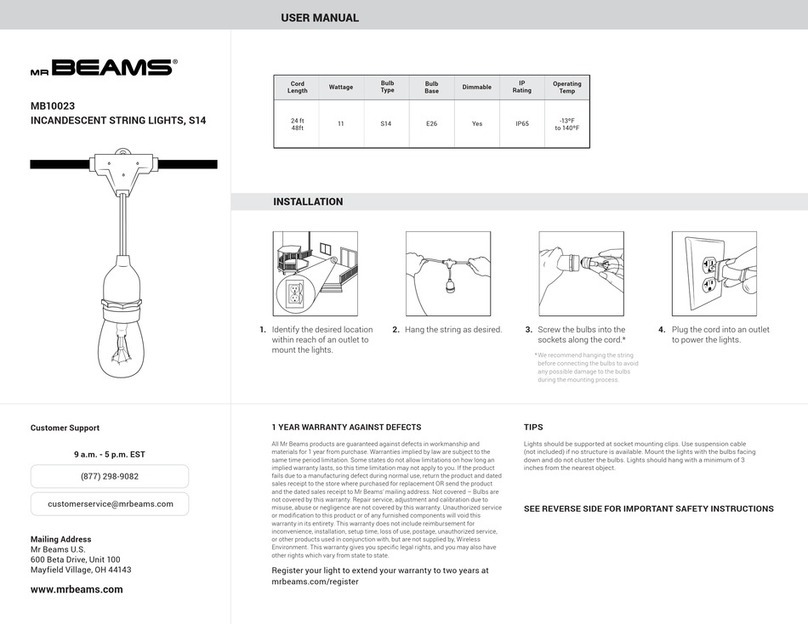
IDS Dual User manual
Popular Lighting Equipment manuals by other brands
Good Earth Lighting
Good Earth Lighting UC1271-WH1-09LF3-G manual
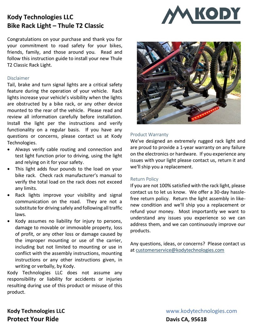
Kody Technologies
Kody Technologies Thule T2 Classic Installation instruction

Beamz
Beamz BX100 instruction manual
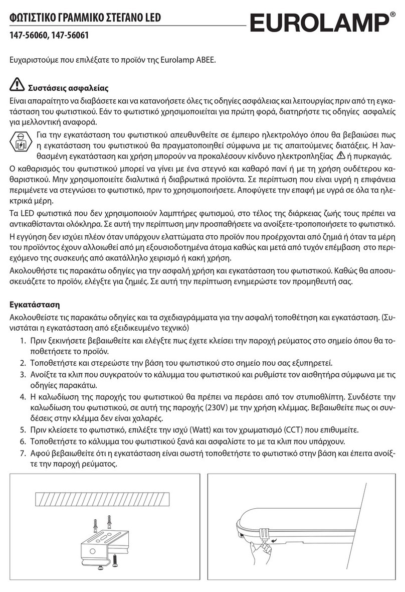
EUROLAMP
EUROLAMP 147-56060 quick start guide
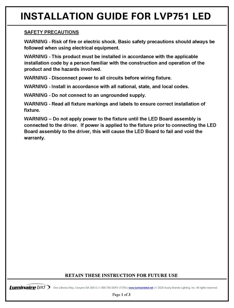
Luminaire led
Luminaire led LVP751 installation guide
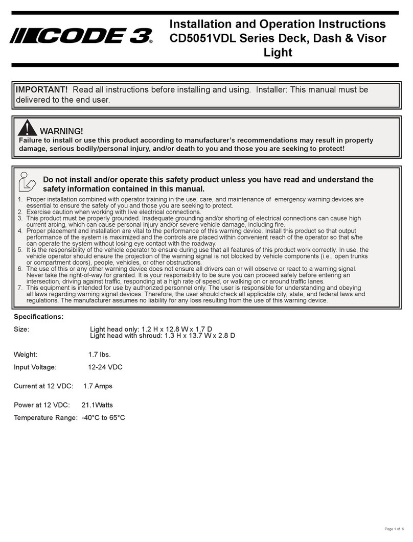
Code 3
Code 3 CD5051VDL Series Assembly, installation and operation instructions

Knightsbridge
Knightsbridge BL12LEDS Installation & maintenance manual

ML Accessories
ML Accessories 12DCIP40 Installation & maintenance manual
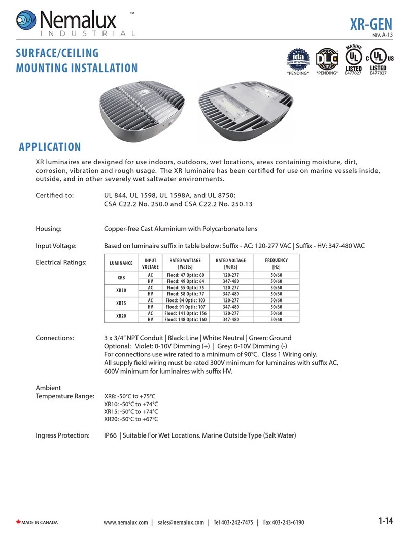
Nemalux
Nemalux XR-GEN Series Installation & Mounting Guide
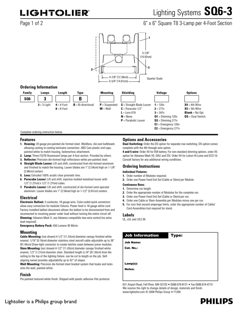
Philips
Philips Lightolier SQ6-3 Specifications
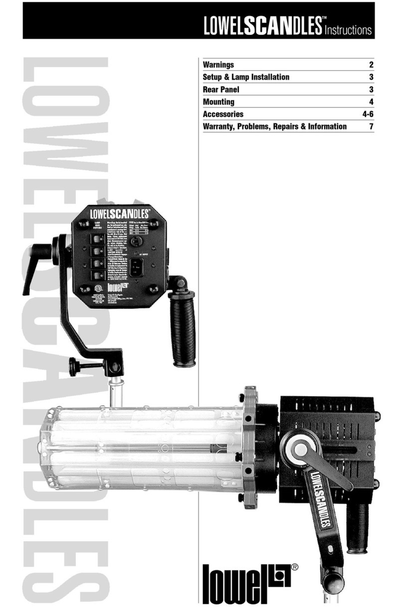
Lowel
Lowel Scandles LSF-24DA instructions

MAGMATIC
MAGMATIC PRISMA MINI BAR 20 user manual


