IDTECH SecureHead SPI User manual

ID TECH
10721 Walker Street, Cypress, CA 90630-4720
Tel: (714) 761-6368 Fax (714) 761-8880
www.idtechproducts.com
USER MANUAL
SecureHead™ Encrypted Magnetic
Read Head
With TriMagIV ASIC
SPI Interface
80101502-002 Rev J
28 September 2020

ID TECH SecureHead SPI with TMIV User Manual
Page | 2
Copyright © 2020 ID TECH. All rights reserved.
This document, as well as the software and hardware described in it, is furnished under license and may be
used or copied online in accordance with the terms of such license. The content of this document is furnished
for information use only, is subject to change without notice, and should not be construed as a commitment by
ID TECH. While every effort has been made to ensure the accuracy of the information provided, ID TECH
assumes no responsibility or liability for any unintentional errors or inaccuracies that may appear in this
document. Except as permitted by such license, no part of this publication may be reproduced or transmitted by
electronic, mechanical, recording, or otherwise, or translated into any language form without the express
written consent of ID TECH.
Agency Approved
Specifications for subpart B of part 15 of FCC rule for a Class A computing device.
Limited Warranty
ID TECH warrants to the original purchaser for a period of 12 months from the date of invoice that this product
is in good working order and free from defects in material and workmanship under normal use and service. ID
TECH’s obligation under this warranty is limited to, at its option, replacing, repairing, or giving credit for any
product which has, within the warranty period, been returned to the factory of origin, transportation charges
and insurance prepaid, and which is, after examination, disclosed to ID TECH’s satisfaction to be thus defective.
The expense of removal and reinstallation of any item or items of equipment is not included in this warranty. No
person, firm, or corporation is authorized to assume for ID TECH any other liabilities in connection with the
sales of any product. In no event shall ID TECH be liable for any special, incidental, or consequential damages to
Purchaser or any third party caused by any defective item of equipment, whether that defect is warranted
against or not. Purchaser’s sole and exclusive remedy for defective equipment, which does not conform to the
requirements of sales, is to have such equipment replaced or repaired by ID TECH. For limited warranty service
during the warranty period, please contact ID TECH to obtain a Return Material Authorization (RMA) number &
instructions for returning the product.
THIS WARRANTY IS IN LIEU OF ALL OTHER WARRANTIES OF MERCHANTABILITY OR FITNESS FOR
PARTICULAR PURPOSE. THERE ARE NO OTHER WARRANTIES OR GUARANTEES, EXPRESS OR IMPLIED,
OTHER THAN THOSE HEREIN STATED. THIS PRODUCT IS SOLD AS IS. IN NO EVENT SHALL ID TECH BE LIABLE
FOR CLAIMS BASED UPON BREACH OF EXPRESS OR IMPLIED WARRANTY OF NEGLIGENCE OF ANY OTHER
DAMAGES WHETHER DIRECT, IMMEDIATE, FORESEEABLE, CONSEQUENTIAL OR SPECIAL OR FOR ANY
EXPENSE INCURRED BY REASON OF THE USE OR MISUSE, SALE OR FABRICATIONS OF PRODUCTS WHICH DO
NOT CONFORM TO THE TERMS AND CONDITIONS OF THE CONTRACT.
©2017-2020 International Technologies & Systems Corporation. The information contained herein is provided
to the user as a convenience. While every effort has been made to ensure accuracy, ID TECH is not responsible
for damages that might occur because of errors or omissions, including any loss of profit or other commercial
damage. The specifications described herein were current at the time of publication but are subject to change at
any time without prior notice.
ID TECH is a registered trademark of International Technologies & Systems Corporation. SecureHead and Value
through Innovation are trademarks of International Technologies & Systems Corporation.

ID TECH SecureHead SPI with TMIV User Manual
Page | 3
Revision History
Rev
Date
Description of Changes
By
A
10/15/2015
•Initial Release
JH
B
09/21/2016
•
Added discussion of Samsung Pay decoding in 4.4.3.
•
Added firmware upgradability to Introduction.
JH
KT
C
11/01/2016
•
Added Firmware Upgrade appendix.
KT
D
02/17/2017
•
Added bits 3-7 definition in notes3 – “Clear/Mask
•
Data Sent Status” in 4.14.8
JW
E
05/15/2017
05/22/2017
•
Changed Appendix J (on firmware updating:. Flow diagrams removed.
•Add note about power management and firmware update.
•
Add expanded discussion of firmware update to Appendix J.
KT
F
12/05/2019
•
Updated section 4.2: Communication Timing
•Corrected header and footer, removed section breaks and replaced them with page
breaks, repaginated layout.
CB
G
07/15/2020
•Updated font/style
•Updated pinout diagrams
CB
H
09/17/2020
•Corrected ACK response; correct ACK is 0x06.
CB
J
09/30/2020
•
Updated sleep current to .01 mA
•Encrypted Output for Decoded Data: Security-Related Function IDs
oUpdated EncryptionID default value to 1.
oRemoved SessionID parameter.
CB

ID TECH SecureHead SPI with TMIV User Manual
Page | 4
Table of Contents
1. INTRODUCTION ...............................................................................................................................................................7
2. SPECIFICATIONS..............................................................................................................................................................7
2.1. Dimensions..............................................................................................................................................................................8
2.2. Mounting Options:.................................................................................................................................................................9
2.3. Head assembly only: T .........................................................................................................................................................9
3. SPI OPERATION .............................................................................................................................................................10
3.1. SPI Data Transmission......................................................................................................................................................10
3.2. Clock Polarity and Phase..................................................................................................................................................10
3.3. Master Input, Slave Output (MISO) ............................................................................................................................... 11
3.4. Master Output, Slave Input (MOSI) ...............................................................................................................................12
3.5. Data Available Output (DAV) ........................................................................................................................................... 12
3.6. Chip Select ............................................................................................................................................................................ 13
3.7. Voltage Input and Ground ................................................................................................................................................14
3.8. Communication ................................................................................................................................................................... 14
4. CONFIGURATION...........................................................................................................................................................15
4.1. Command Structure........................................................................................................................................................... 15
4.1.1. Commands sent to SecureHead .................................................................................................................................................................15
4.1.2. Response from SecureHead..........................................................................................................................................................................15
4.2. Communication Timing.....................................................................................................................................................16
4.3. Default Settings ..................................................................................................................................................................16
4.4. General Selections..............................................................................................................................................................17
4.5. Change to Default Settings..............................................................................................................................................17
4.6. MSR Reading Settings ...................................................................................................................................................... 17
4.7. Decoding Method Settings ..............................................................................................................................................17
4.7.1. Samsung Pay Encoding/Decoding ............................................................................................................................................................18
4.8. Review Settings .................................................................................................................................................................. 18
4.9. Review Firmware Version................................................................................................................................................18
4.10. Review Serial Number .................................................................................................................................................... 19
4.11. Message Formatting Selections (Only for Security Level 1 & 2) .......................................................................19
4.11.1. Terminator Setting............................................................................................................................................................................................19
4.11.2. Preamble Setting ...............................................................................................................................................................................................19
4.11.3. Postamble Setting.............................................................................................................................................................................................19
4.11.4. Track n Prefix Setting ......................................................................................................................................................................................20
4.11.5. Track n Suffix Setting ......................................................................................................................................................................................20
4.12. Magnetic Track Selections (Only for Security Level 1 & 2) ..................................................................................20
4.12.1. Track_Selection Settings:.............................................................................................................................................................................20
4.12.2. Track Separator Selection............................................................................................................................................................................21
4.12.3. Start/End Sentinel and Track2 Account Number Only.............................................................................................................21
4.13. Security Settings .............................................................................................................................................................. 21
4.13.1. Select Key Management Type...................................................................................................................................................................21
4.13.2. External Authenticate Command (Fixed Key Only) .....................................................................................................................21
4.13.3. Retrieve Encrypted Challenge Command..........................................................................................................................................22
4.13.4. Send External Authenticate Command Host -> Device: ..........................................................................................................22
4.14. Encryption Settings .........................................................................................................................................................22
4.14.1. Review KSN (DUKPT Key management only)..................................................................................................................................23
4.14.2. Review Security Level.....................................................................................................................................................................................23

ID TECH SecureHead SPI with TMIV User Manual
Page | 5
4.14.3. Encrypt External Data Command...........................................................................................................................................................23
4.15. Encrypted Output for Decoded Data..........................................................................................................................24
4.15.1. Encrypt Functions..............................................................................................................................................................................................24
4.15.2. Security Related Function ID......................................................................................................................................................................24
4.16. Security Management ....................................................................................................................................................26
4.16.1. Level 0.......................................................................................................................................................................................................................26
4.16.2. Level 1.......................................................................................................................................................................................................................26
4.16.3. Level 2.......................................................................................................................................................................................................................26
4.16.4. Level 3.......................................................................................................................................................................................................................26
5. ENCRYPTION MANAGEMENT......................................................................................................................................27
5.1. Check Card Format.............................................................................................................................................................27
5.1.1. ISO/ABA (American Banking Association) Card Encoding method......................................................................................27
5.1.2. AAMVA (American Association of Motor Vehicle Administration) Card Encoding method..................................27
6. OTHERS (CUSTOMER CARD)........................................................................................................................................27
6.1. MSR Data Masking.............................................................................................................................................................27
6.1.1. Masked Area ............................................................................................................................................................................................................27
6.2. Level 1 and 2 Data Output Format................................................................................................................................28
6.2.1. Magnetic Track Basic Decoded Data Format ....................................................................................................................................28
6.2.2. Magnetic Track Basic Raw Data Format..............................................................................................................................................28
6.2.3. Definitions..................................................................................................................................................................................................................29
6.3. DUKPT Level 3 Data Output Enhanced Format......................................................................................................... 29
6.3.1. Data length byte....................................................................................................................................................................................................30
6.3.2. Card Encode Type .................................................................................................................................................................................................31
6.4. Track Status .........................................................................................................................................................................31
6.5. Track Data Length ..............................................................................................................................................................31
6.6. Clear/Masked Data sent status .....................................................................................................................................32
6.6.1. Encrypted Hash Data sent status .............................................................................................................................................................32
6.7. Track Masked Data ............................................................................................................................................................32
6.8. Track Encrypted Data........................................................................................................................................................ 32
6.9. Track Hashed Data.............................................................................................................................................................33
6.9.1. Encryption Output Format Setting............................................................................................................................................................33
6.9.2. Encryption Option Setting (for enhanced encryption format only)......................................................................................33
Note:.............................................................................................................................................................................................................................................33
6.9.3. Hash Option Setting:...........................................................................................................................................................................................33
6.10. Mask Option Setting ....................................................................................................................................................... 34
6.11. Note 1 : Card Encode Type ............................................................................................................................................ 34
6.12. Note 2: Track1-3 status byte....................................................................................................................................... 34
6.13. Note 3: Clear/mask data sent status.........................................................................................................................35
6.14. Note 4: Encrypted/Hash data sent status................................................................................................................35
6.14.1. Fixed Key Management Data Output Enhanced Format........................................................................................................35
7. APPENDIX A: DEFAULT SETTING TABLE....................................................................................................................36
8. APPENDIX B: MAGNETIC STRIPE STANDARD FORMATS ........................................................................................37
8.1. ISO Credit Card Format .....................................................................................................................................................37
8.1.1. Track1...........................................................................................................................................................................................................................37
8.1.2. Track2...........................................................................................................................................................................................................................37
8.2. AAMVA Driver’s License Format.................................................................................................................................... 37
8.2.1. Track1...........................................................................................................................................................................................................................37

ID TECH SecureHead SPI with TMIV User Manual
Page | 6
8.2.2. Track2...........................................................................................................................................................................................................................38
8.2.3. Track3...........................................................................................................................................................................................................................38
9. APPENDIX C: OTHER MODE CARD DATA OUTPUT ...................................................................................................39
10. APPENDIX D: GUIDE TO ENCRYPTING AND DECRYPTING DATA .........................................................................39
11. APPENDIX E: KEY MANAGEMENT FLOW CHART ...................................................................................................40
12. APPENDIX F: EXAMPLE OF DECODED DATA DECRYPTION ..................................................................................41
Security Level 3 Decryption - Enhanced Encryption Format.......................................................................................41
13. APPENDIX G: EXAMPLE OF ID TECH RAW DATA DECRYPTION ...........................................................................44
Original Raw Data Forward Direction..................................................................................................................................44
Original Raw Data Backward Direction............................................................................................................................... 44
Example of decryption of a two track ABA card with the original encryption format. For both Fix & DUKPT
key management.......................................................................................................................................................44
SecureHead Reader with default settings .......................................................................................................................................................44
Original Encryption Format .........................................................................................................................................................................................44
14. APPENDIX H: EXAMPLE OF SPI MASTER CHIP CONTROLLING............................................................................46
15. APPENDIX I: MAGNETIC HEADS MECHANICAL DESIGN GUIDELINES.................................................................51
16. APPENDIX J: FIRMWARE UPGRADE.........................................................................................................................56
16.1. Procedure ........................................................................................................................................................................... 56
16.2. Basic steps:........................................................................................................................................................................56
16.3. Load new firmware .........................................................................................................................................................56
16.4. Example ..............................................................................................................................................................................57

ID TECH SecureHead SPI with TMIV User Manual
Page | 7
1. Introduction
The SPI SecureHead™ magnetic stripe reader can read 1, 2, or 3 tracks of magnetic stripe information.
When connected to the host, the SecureHead is completely compatible with SPI (Serial Peripheral
Interface). The raw data or decoded data go to the host via SPI. Also, firmware can be upgraded via
SPI.
The SecureHead supports both unencrypted and encrypted data output. When encryption is not
turned on, the decoded data can be formatted with preamble/postamble and terminator characters
to match the format expected by the host.
2. Specifications
General
Card Speed
3 to 75 ips (7.6 to 190.5 cm/s)
Electrical
Power Supply
3.0 to 3.6 VDC
I/O Voltage Range
2.7 to 3.6 VDC
Current
Active Power Supply Current
5
mA Standby Power Supply Current
0.03 mA
Environmental
ESD
+4kV discharge to head
Operating Temperature
0 °C to 55 C
Storage Temperature
-40 °C to 70 °C
Humidity
-10% to 90% non-condensing
Mechanical
Weight
5.67 grams
Cable Length
125 +/- 6.4 mm
Note 1: During the analog components’ wake up, a few capacitors are charged up, and the wake-up
inrush current can go up to 40 mA for no more than 5 μsec.
Note 2: During the chip power up, the internal regulator can introduce 80 mA current for 50 μsec.
Note 3: ID TECH recommends that you incorporate the ability to separately control power to the SPI
TrimagIV SecureHead. During the firmware update procedure, there is a short time (a few seconds)
during which, if power is removed from the device, firmware loading can fail. The host software can
cycle the power of SecureHead to get the unit back to bootload mode again, then the host needs to
talk to the unit within ~500 msec and continue loading firmware. Please check Tech Note 015 for
details (available for download on the ID TECH Knowledge Base.)
For normal operation, we do not recommend turning off the power of the unit. Also, do not turn off
the power within 2 seconds after receiving MSR data.
ID TECH SecureHead SPI with TMIV User Manual
Page | 8
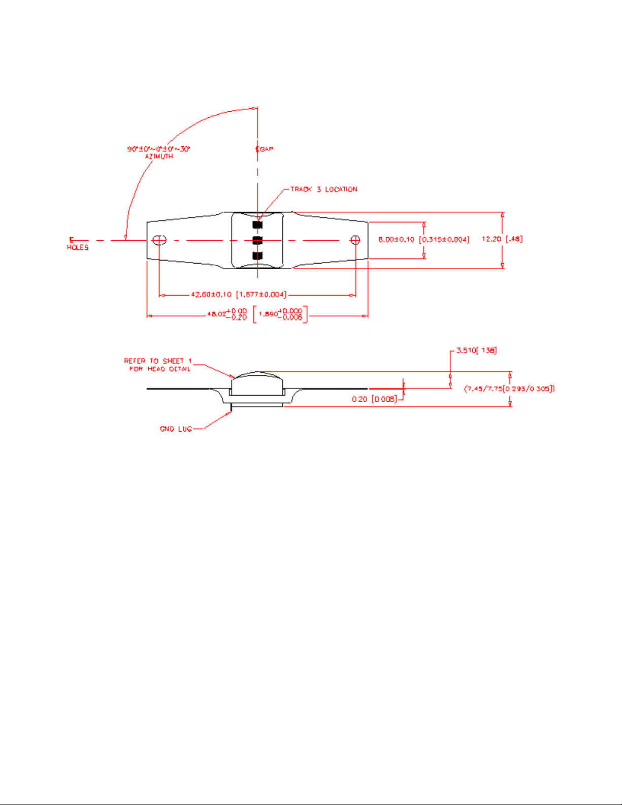
2.1. Dimensions
ID TECH SecureHead SPI with TMIV User Manual
Page | 9
2.2. Mounting Options:
Wing spring mounting: This is the standard mounting option and can be used on most swipe readers.
The protrusion of the head from the surface of the spring is 3.50 mm.
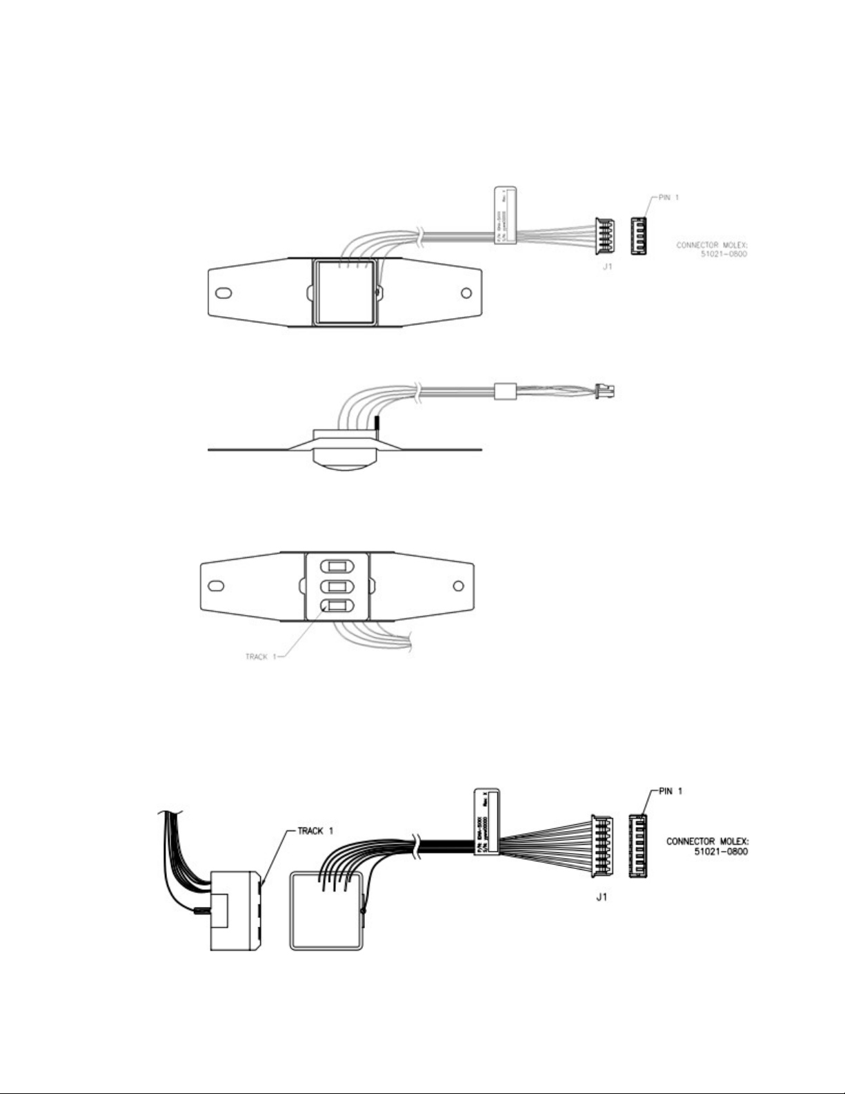
2.3. Head assembly only: T
his option is provided for special applications.
The mechanical interface is an eight-pin male Molex Connector 51021-0800 for option 1 and 2.

ID TECH SecureHead SPI with TMIV User Manual
Page | 10
3. SPI Operation
This section describes SPI (Serial Peripheral Interface), the SPI bus interface timing, communication
protocol, timeouts, and data output format. The following table shows the signals used in the SPI
interface. Note that the connector is an eight-pin Molex 51021-0800.
PIN #
Signal
Description
1
SPCK
Serial Clock Input
2
MISO
Master Input, Slave Output
3
MOSI
Master Output, Slave Input
4
DAV
Data Available (output)
5
NCS
Chip Select, Active Low
6
VIN
Voltage Input
7
GND
Logic Ground
8
Head Case GND
Chassis Ground
3.1. SPI Data Transmission
A serial peripheral interface (SPI) is an interface that enables the serial exchange of data between two
devices, one called a master and the other called a slave. The host (master) generates the clock signal
(SPCK) to trigger data exchange on the SPI bus.
During each SPI clock cycle, data are transmitted in both directions at the same time (full duplex
transmission):
•On the MOSI line, the master sends a bit and the slave reads it
•On the MISO line, the slave sends a bit and the master reads it
The SPI bus transmits data in 8-bit data groups, sending data one bit at a time, from MSB to LSB. An
example of bit transmission for byte A and byte B (of two-byte quantity AB) would be
A(bit 7) A(bit 6) … A(bit 0) B(bit 7) B(bit 6) … B(bit 0).
3.2. Clock Polarity and Phase
The clock polarity and phase have four different options with respect to the data. The serial clock
input frequency can go up to 1M bps.
•When clock polarity = 0, the base value of the clock is 0
oFor clock phase = 0, data are read on the clock's rising edge (low->high
transition) and data are changed on a falling edge (high->low transition).
oFor clock phase = 1, data are read on the clock's falling edge and data are
changed on a rising edge.
oWhen clock polarity = 1, the base value of the clock is 1
oFor clock phase = 0, data are read on clock's falling edge and data are

ID TECH SecureHead SPI with TMIV User Manual
Page | 11
changed on a rising edge.
oFor clock phase = 1, data are read on clock's rising edge and data are
changed on a falling edge.
The signal is required to read card data from the device. The device default uses clock phase = 0 and
clock polarity = 0. Custom defaults for device clock phase and polarity are available upon request.
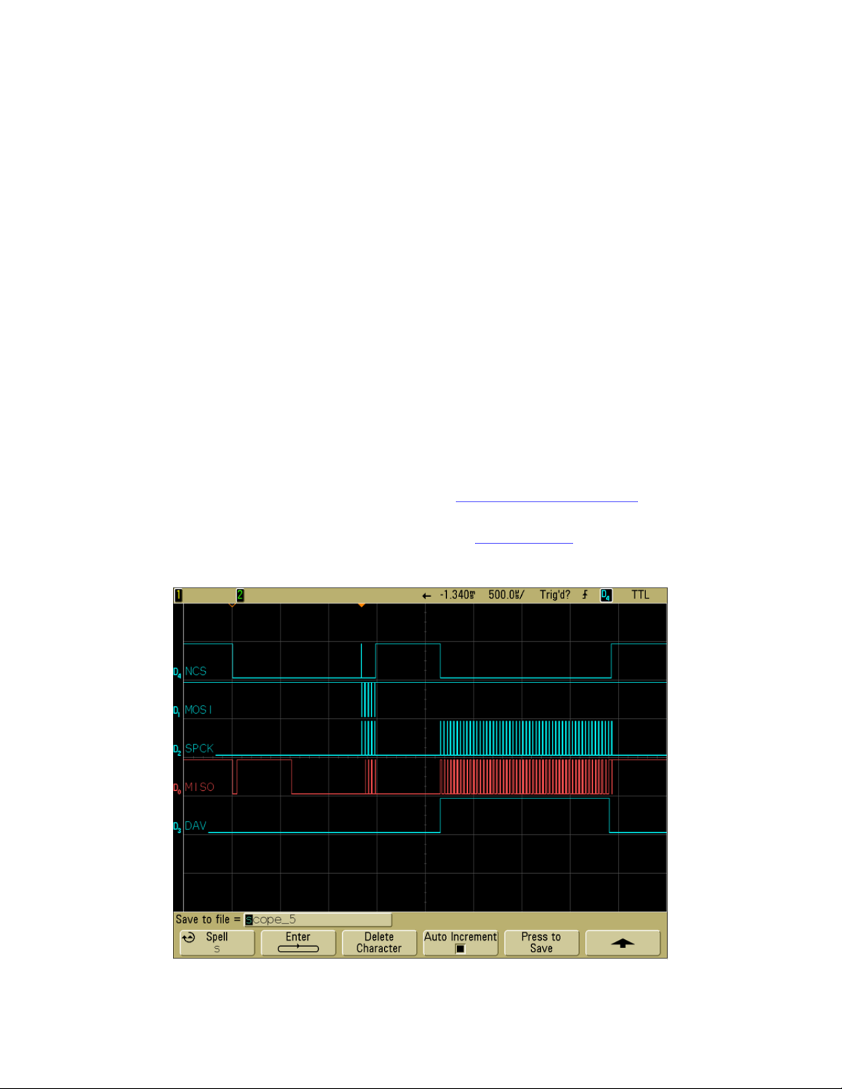
The following picture shows an example of regular TM4 SPI firmware with clock polarity = 0 and clock
phase = 0. The data are read on the rising edge of the clock and changed on the falling edge. On MOSI
line, the host sends out data of 00000010, or 02h (0x02).
3.3. Master Input, Slave Output (MISO)
The MISO signal is the serial data output sent from for the device. It is also the data line that is
received by the host. When the device is not active (Chip Select is high), the MISO becomes high
impedance (disconnected). The MISO signal would be in an indeterminate state after the device is
power-cycled or reset for a maximum of 1 second. This signal should be ignored during this time.
ID TECH SecureHead SPI with TMIV User Manual
Page | 12
3.4. Master Output, Slave Input (MOSI)
The MOSI signal is the serial data input for the device and serial data output for the host. This signal is
sent from the host (master) to the device (slave). The signal might not be required after some device
parameters such as the device key has been set and saved. Set the signal to be high if it is not being
used.
3.5. Data Available Output (DAV)
The DAV signal is low where there is no data to be transmitted. When the DAV signal is high, it
indicates that there is data available for output. The host and then sends out the clock signal to read
the data. After all the data is transmitted, the device sets the DAV signal low again.
The signal can be used for the host to determine if the device has data ready to transmit. However,
the signal should be ignored right after (1 second maximum) the power cycle or a reset, as it would be
in an indeterminate state.
In the case when the DAV signal is not used, the host will need to poll the device periodically to
determine if it has data to transmit. The host needs to toggle SCL to get card data from MISO. The
first non-IDLE byte indicates the start of valid card data. IDLE is FF. For more details, please refer to
the communication protocol section of this document in the chapter on Configuration.
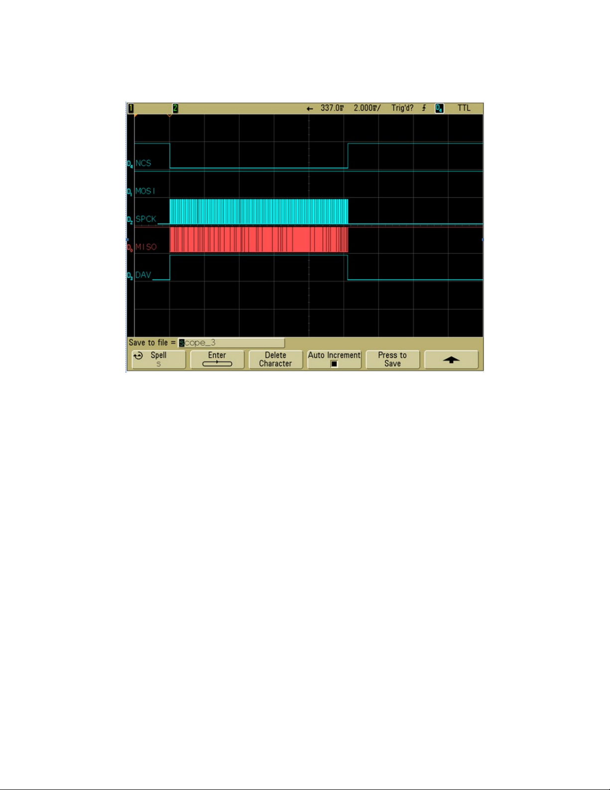
The following graph shows the command and response for Review Version command. The last signal
shown in the graph is the DAV signal:
ID TECH SecureHead SPI with TMIV User Manual
Page | 13
After the command is received and the response is ready, the DAV would be set too high for the host
to receive response. After the response is received, the DAV would be low, indicating there is no more
data to be transmitted.
After receiving a command, typically within less than 20ms, response is ready and DAV set
to high. For some specific commands, the delay may be longer.
After the last byte of response is sent, the DAV is pulled low. If user polls DAV status to check
whether there are data available, we suggest using 100μs polling interval and throw away any data
when DAV is low.
3.6. Chip Select
SPI interface allows connecting several SPI devices while master selects each of them with NCS (Chip
Select, Active Low). The device will only respond to SPCK and MOSI signals after an NCS is pulled low.
For the first byte of each command sent to SecureHead, NCS needs to be pulled low for 1 millisecond
before the clock line. Because SecureHead is always in deep sleep mode when in idle status, this 1
millisecond delay is required to allow SecureHead wake up from sleep mode.
ID TECH SecureHead SPI with TMIV User Manual
Page | 14
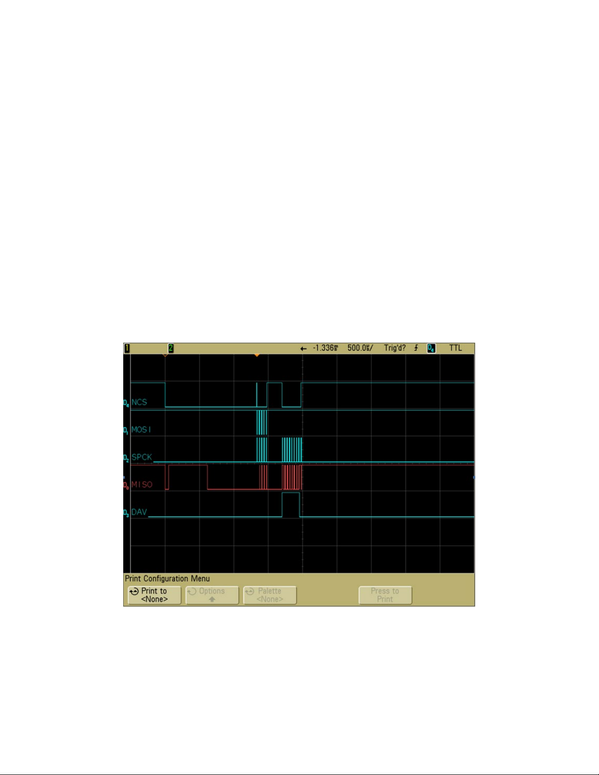
When the user swipes a card, no delay is required. Following is the waveform for MSR output:
3.7. Voltage Input and Ground
The VIN signal is the power input for the device and has an operating range of 3.0 to 3.6 volts DC. The
GND signal is logic ground. The head case GND signal is chassis ground, which is connected to the
head case. For optimum ESD protection, this signal should be connected to earth ground.
3.8. Communication
When the host has a frame to send, it pulls the NCS line low, waits 1 millisecond, then clocks it out.
When the device has a frame to send, it raises its data available (DAV) signal and waits for the host to
pull the NCS line low, then clock in the frame. The host normally clocks out IDLE characters to clock in
a frame from the device. Because the device typically loads its one transmit buffer with IDLE byte
when it has nothing to transmit, the first byte clocked out from the device after the DAV signal is
asserted could be IDLE instead of a valid byte. If this is the case, simply discard this byte.
To detect whether the device has a frame to send, the host can either monitor the DAV signal or,
optionally, periodically clock in up to two bytes from the device to see if the device has sent a valid
data. Up to two bytes should be clocked in instead of just one because the first byte could be an IDLE
byte that was loaded into the device’s transmit buffers before the device had anything to send. The
host should look at each byte it clocks in to see if it is a valid byte. If a valid byte is found, then the
subsequent bytes will contain the frame.

ID TECH SecureHead SPI with TMIV User Manual
Page | 15
4. Configuration
The SecureHead reader must be appropriately configured to your application. Configuration settings
enable the reader to work with the host system. Once programmed, these configuration settings are
stored in the reader’s non-volatile memory (so they are not affected by the cycling of power).
In TriMag IV, ACK is 0x06.
4.1. Command Structure
4.1.1. Commands sent to SecureHead
a.
Setting Command:
<STX><S>[<FuncID><Len><FuncData>…]<ETX><CheckSum>
b.
Read Status Command:
<STX><R><FuncID><ETX><CheckSum>
c.
Special Function Command:
<STX>[<FuncID><Len><FuncData>…]<ETX><CheckSum>
4.1.2. Response from SecureHead
a.
Setting Command
Host
SecureHead
Setting
Command
<ACK> if OK
or
<NAK> if Error
b.
Read Status Command
Hos
t
SecureHead
Read Status Command
<ACK> and <Response> if OK
or
<NAK> if Error

ID TECH SecureHead SPI with TMIV User Manual
Page | 16
c.
Special Function Command
Hos
t
SecureHead
Special Function
Command
<ACK> and <Response>
if OK
or
<NAK> if Error
Where:
<STX>
02h
<S>
Indicates setting commands. 53h
<R>
Indicates read status commands. 52h
<FuncID>
One-byte Function ID identifies the
Specific function or settings affected.
<Len>
One-byte length count for the following data
block<FuncData>
<FuncData>
Data block for the function
<ETX>
03h
<CheckSum>
Check Sum: The overall Modulo 2 (Exclusive OR) sum (from <STX> to
<CheckSum>) should be zero.
<ACK>
06h
<NAK>
15h
4.2. Communication Timing
The power up time for TMIV SecureHead is 600ms. The typical delay for the reader to respond to a
command is 20ms; the maximum delay for the reader to respond can be as much as 40ms. Caution
must therefore be taken to maintain an appropriate delay between two commands.
4.3. Default Settings
The SecureHead reader is shipped from the factory with the default settings already programmed. In
the following sections, the default settings are shown in boldface.
For a table of default settings, see Appendix A.

ID TECH SecureHead SPI with TMIV User Manual
Page | 17
4.4. General Selections
This group of configuration settings defines the basic operating parameters of SecureHead.
4.5. Change to Default Settings
Command: <STX><S><18h><ETX><CheckSum>
This command does not have any <FuncData>. It returns all settings for all groups to their default
values.
4.6. MSR Reading Settings
Enable or Disable the SecureHead. If the reader is disabled, no data will be sent out to the host.
Command: <STX><S><1Ah><01h><MSR Reading Settings><ETX><CheckSum>
MSR Reading Settings:
•“0” MSR Reading Disabled
•“1” MSR Reading Enabled
4.7. Decoding Method Settings
The SecureHead can support four kinds of decoded directions.
Command: <STX><S><1Dh><01h><Decoding Method Settings><ETX><CheckSum>
Decoding Method Settings:
•“0”: Raw Data Decoding in Both Directions, sent out in ID TECH mode.
•“1”: Decoding in Both Directions. If the encryption feature is enabled, the key management
method used is DUKPT.
•“2”: Moving stripe along head in direction of encoding. If the encryption feature is enabled, the
key management method used is DUKPT.
•“3”: Moving stripe along head against direction of encoding. If the encryption feature is
enabled, the key management method used is DUKPT.
•“4”: Raw Data Decoding in Both Directions, send out in other mode. If the encryption feature
is enabled, the key management method used is fixed key.
With the bi-directional method, the user can swipe the card in either direction and still read the data
encoded on the magnetic stripe. Otherwise, the card can only be swiped in one specified direction to
read the card. Raw Decoding just sends the card’s magnetic data in groups of 4 bits per character.
The head reads from the first byte of each track, starting from the most significant bit. The data start
to be collected when the first 1 bit is detected. No checking is done except to verify that the track has,
or does not have, magnetic data.

ID TECH SecureHead SPI with TMIV User Manual
Page | 18
4.7.1. Samsung Pay Encoding/Decoding
Special track decoding considerations apply to Samsung Pay interactions. Samsung Pay/MST
(LoopPay) sends out a magnetic signal to a magnetic head. So MCUs may receive identical magnetic
signals on all tracks. However, Samsung Pay devices send out Track1 and Track2 data consecutively,
making it possible to disambiguate the tracks.
If the reading device receives identical MSR data for multiple tracks, MSR processing will ignore
Track2 and Track3 data if the card data is ISO 7-bit encoded, treating it as Track1 data . If the data are
5-bit encoded, it is received as Track2 data only.
If MSR receives single track data corresponding to ABA, IATA, or ISO 4909, but not in the expected
track, the data will be ignored to avoid capturing track data as an incorrect type. The processor will
not move data from one track to another.
4.8. Review Settings
Command: <STX><R><1Fh><ETX><CheckSum>
This command does not have any <FuncData>. It activates the review settings command.
SecureHead sends back an <ACK> and <Response>.
<Response> format:
The current setting data block is a collection of many function-setting blocks <FuncSETBLOCK> as
follows:
<STX><FuncSETBLOCK1>…<FuncSETBLOCKn><ETX><CheckSum>
Each function-setting block <FuncSETBLOCK> has the following format:
<FuncID><Len><FuncData>
Where:
•<FuncID> is one byte identifying the setting(s) for the function.
•<Len> is a one-byte length count for the following function-setting block <FuncData>
•<FuncData> is the current setting for this function. It has the same format as in the sending
command for this function.
•<FuncSETBLOCK> are in the order of their Function ID<FuncID>
4.9. Review Firmware Version
Command: <STX><R><22h><ETX><CheckSum>
This command gets the device firmware version.

ID TECH SecureHead SPI with TMIV User Manual
Page | 19
4.10. Review Serial Number
Command: <STX><R><4Eh><ETX><CheckSum>
This command gets the device serial number.
4.11. Message Formatting Selections (Only for Security Level 1 & 2)
4.11.1. Terminator Setting
Terminator characters are used to end a string of data in some applications.
Command: <STX><S><21h><01h><Terminator Settings><ETX><CheckSum>
<Terminator Settings>: Any one character, 00h is none; default is CR (0Dh).
4.11.2. Preamble Setting
Characters can be added to the beginning of a string of data. These can be special characters for
identifying a specific reading station, to format a message header expected by the receiving host, or
any other character string. Up to fifteen ASCII characters can be defined.
Command: <STX><S><D2h><Len><Preamble><ETX><CheckSum>
Where:
•<Len>= the number of bytes of preamble string
•<Preamble> = {string length}{string}
NOTE: String length is one byte, maximum fifteen <0Fh>.
4.11.3. Postamble Setting
The postamble serves the same purpose as the preamble, except it is added to the end of the data
string, after any terminator characters.
Command: <STX><S><D3h><Len><Postamble><ETX><CheckSum>
Where:
•<Len> = the number of bytes of postamble string
•<Postamble> = {string length}{string}
NOTE: String length is one byte, maximum fifteen <0Fh>.

ID TECH SecureHead SPI with TMIV User Manual
Page | 20
4.11.4. Track n Prefix Setting
Characters can be added to the beginning of a track data. These can be special characters to identify
the specific track to the receiving host, or any other character string. Up to six ASCII characters can be
defined.
Command: <STX><S><n><Len><Prefix><ETX><CheckSum>
Where:
•<n> = 34h for Track1; 35h for Track2 and 36h for Track3
•<Len> = the number of bytes of prefix string
•<Prefix> = {string length}{string}
NOTE: String length is one byte, maximum six.
4.11.5. Track n Suffix Setting
Characters can be added to the end of track data. These can be special characters to identify the
specific track to the receiving host, or any other character string. Up to six ASCII characters can be
defined.
Command: <STX><S><n><Len><Suffix><ETX><CheckSum>
Where:
<n> = 37h for Track1; 38h for Track2 and 39h for Track3
<Len> = the number of bytes of suffix string
<Suffix> = {string length}{string}
NOTE: String length is one byte, maximum six.
4.12. Magnetic Track Selections (Only for Security Level 1 & 2)
There are up to three tracks of encoded data on a magnetic stripe. This option selects the tracks that
will be read and decoded.
Command: <STX><S><13h><01h><Track_Selection Settings><ETX><CheckSum>
4.12.1. Track_Selection Settings:
•“0” Any Track
•“1” Require Track1 Only
•“2” Require Track2 Only
•“3” Require Track1 & Track2
•“4” Require Track3 Only
•“5” Require Track1 & Track3
•“6” Require Track2 & Track3
Table of contents
Popular Accessories manuals by other brands


Oster
Oster Fusion BRLY07 user manual

OK International
OK International CW1-RC Series Operation manual

Everflourish
Everflourish EMW200R-UL instruction manual

Mockett
Mockett PCS100C-U quick start guide

Flymo
Flymo ELECTRIC DUMP SYSTEM manual

VARSITY Scoreboards
VARSITY Scoreboards VSBX-742 operating instructions


