IDTECK PRG2000S User manual
User’s Manual
13.56MHz [MIFARE]
Contactless Smart Card User Credential Programmer

2
Table of Contents
1. Important Safety Instructions........................................................................................ 3
2. Product Overview........................................................................................................... 3
3. Features .......................................................................................................................... 4
4. Package Contents .......................................................................................................... 4
5. Specifications................................................................................................................. 5
6. Installation ...................................................................................................................... 5
7. Wire Colors..................................................................................................................... 6
8. Connection to PC or SR S Series Reader..................................................................... 7
9. Operations ...................................................................................................................... 7
10. Appendix....................................................................................................................... 8
11. FCC Registration Information...................................................................................... 9
12. Warranty Policy and Limitation of Liability ...............................................................10
13. How to Make RMA Request (After Sales Service).....................................................11

3
1. Important Safety Instructions
When using the 13.56MHz [MIFARE] Contactless Smart Card User Credential Programmer, basic
safety precautions should always be followed to reduce the risk of fire, electrical shock, and injury to
persons. In addition, the following should also be followed:
1. Fully read and understand all instructions and follow them completely.
2. Follow all warnings and instructions marked on the product.
3. Do not use liquid or aerosol cleaners. Use a damp cloth for cleaning. If necessary, use mild soap.
4. Do not use this product near water.
5. Only operate this product using the type of power source indicated. If you are not sure of the type
of power supplied to your installation site, consult your dealer of local power company.
6. Never insert objects of any kind into the product or through the cabinet slots as they may touch
voltage points and/or short circuit parts possibly resulting in fire or electric shock.
Never spill liquid of any kind on the product.
7. Never disassemble this product by yourself; take the unit to a qualified service center whenever
service or repair is required. Opening or removing the covers may expose you to dangerous
voltages or other risks. Also, incorrect reassembly can cause electric shock when the unit is
subsequently used.
8. Unplug this product from the Direct Current (DC) power source and refer to qualified service
personnel under these conditions:
When the power supply cord or plug is damaged or frayed.
If liquid has been spilled on the product.
If the product does not operate normally after following the operating instructions in this
manual. Adjust only those controls that are covered by the operating instructions in this
manual. Improper adjustment of other controls that are not covered by this manual may
damage the unit and will often require extensive work by a qualified technician to restore
normal operation.
If the product exhibits a distinct change in performance.
2. Product Overview
The IDTECK PRG2000S (SMART [MIFARE○
R] CARD User Credential PROGRAMMER) is a device
which allows users to issue Philips Mifare cards with IDs that they choose, using the user-defined data
format and various settings. The IDTECK PRG2000S is also capable of configuring the settings of SR S
Series readers. The IDTECK PRG2000S can send the setting data that it used in issuing cards to an SR S
Series reader so that the unit can read the card issued by the IDTECK PRG2000S. The IDTECK
PRG2000S has two RS-232C communication cables, enabling communication with a PC and a SR S
Series reader. The IDTECK PRG2000S has seven 2-color LEDs (green and red) and a buzzer which notify
users of its operating status.

4
3. Features
-SMART [MIFARE○
R] Reader & Writer with Maximum Read Range of 10 cm.
-Various Wiegand & ABA Track II Output Settings Selectable
-Issues ID Numbers Using Encrypted Keys
-Key Value Settings Selectable for Different Sectors
-Able to Send Card Issuance Setting Data to SR S Series Reader.
-7ea of two-color LED Indicators (Red/Green) and Buzzer
-2ea of RS232 Serial Communication Cables
-Operates at Supply Voltages from DC10V to DC15V
4. Package Contents
Please, unpack the package and check its contents. If any of the following items is missing, contact a
nearby distributor.
Reader Module PRG2000S Bezel User Manual Table Holder &Screws Connector Board
(1ea) (1ea) (1 Copy) (1ea & 4ea) (1ea)
12VDC Adaptor RS-232 Communication Cable S/W CD-ROM ISC80 Cards
(1ea) (1ea) (1 CD) (5 cards)
5
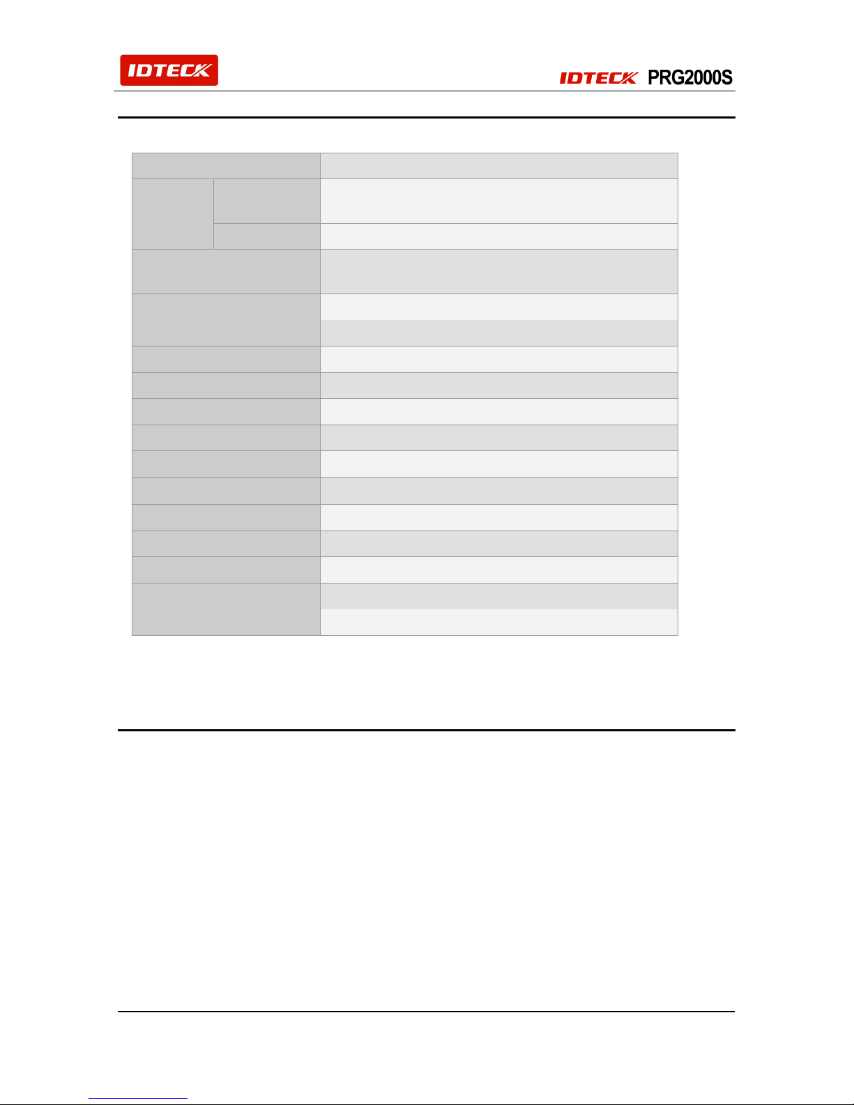
5. Specifications
CPU
8bit Microprocessor
Memory
Program
Memory
128KByte ROM
Data Memory
4KByte EEPROM
Reader
Built-in Contactless Smart Card [MIFARE] Reader
(Read and Write)
Overwrite Time (Card)
Less than 2s
Reading Time (Card)
Less than 1s
Power / Current
Adapter (AC110V / 220V, Output DC12V, 1A)
Input Port
2ea for RS232 Communication
LED Indicator / Beeper
7 Array LED Indicators (Red and Green) / Piezo Buzzer
Data Encryption
Crypto Encryption Algorithm
Software
PRG2000S Programmer Included
Operating Temperature
0to +50C (+32to +122F)
Operating Humidity
10% to 90% relative humidity non-condensing
Color
Dark Pearl Gray
Material
Polycarbonate
Dimension (WxHxT)
102mmX142mmX 23mm (4.02’’X5.59’’X0.90’’)
Weight
180g (0.39lbs)
6. Installation
6-1. Assembly of PRG2000S and Table Holder
1) Separate the PRG2000S bezel and the Reader Module. If necessary, use tools like a slotted
screwdriver.
2) Assemble the Table Holder and Connector Board as shown on the next page.
3) Connect the PRG2000S to J1 of the Connector Board
4) Connect the SR S Series reader to J2, to make easy the configuration of the S Series product.

6
Figure: Assembly Diagram
6-2. Distance between PRG2000S and SR S Reader
1) When configuring a reader and issuing cards using PRG2000S connected to SR 10/30 S Reader,
these two devices need to be separated from each other at least 25 cm.
※Otherwise, they interfere each other and an error may occur.
7. Wire Colors
POWER
Main Power (DC 12V) DC (+12V) Red
Power (Ground) GND Black
OUTPUT (RS232 Format, PC <-> PRG2000S)
RS232C TXD Blue
RS232C RXD Purple
RS232C GND Black
OUTPUT (RS232 Format, PRG2000S <-> SR S SERIES Reader)
RS232C TXD Brown
RS232C RXD Yellow
RS232C GND Black
N/A (Not Available)
White, Green, Orange, Gray

7
8. Connection to PC or SR S Series Reader
9. Operations
When power is applied, the PRG2000S beeps and turns on the LEDs in the order of red > green >
red > green. Then, the LEDs turn off for a while and turn on in red again, one by one, from left to
right while the buzzer beeps.
After power-on, the PRG2000S performs commands that PRG2000S software assigns it.
After a successful operation is completed, the buzzer beeps once and the red LEDs turn off and,
then, the green LEDs turn on, one by one, from the left.
If an operation isn’t successfully completed (i.e. if an error occurs), the buzzer beeps twice and the
red LEDs blink at once.
※If the PRG2000S does not operate as described above, refer to 10. Appendix.
※Please refer to PGR2000S software manual for more details about software installation
and operation.
PC or SR S Series
Main Power (+12V)
Power Ground (GND)
RS232 to PC (GND)
RS232 to PC (TX)
RS232 to PC (RX)
RS232 to SR S (GND)
RS232 to SR S (TX)
RS232 to SR S (RX)
N/A
N/A
N/A
N/A
Black
Purple
Blue
Black
Yellow
Brown
White
Green
Orange
Gray
Red
Black

8
10. Appendix
10-1. Troubleshooting
Cards won’t be recognized.
CAUSE
Due to not using standard voltage (DC12V) or due to an incompatible card type.
SOLUTIONS
1. Confirm the standard voltage information in the User Manual or the Catalog.
2. Make sure that the card is a PHILIPS MIFARE card.
>> You can’t use an 125KHz type of card. But, 13.56MHz cards can be used if they are
the ISO14443 B Type or ISO15693.
(For information about the cards, contact the place where you purchased them.)
3. Make sure that the format of the card is compatible with that of the reader.
>> There are two ways to use a reader; using a serial number (UID) and encoding data to
certain sector and blocks. In the second case, make sure the card and the reader use
the same format.
(For information about the cards, contact the place where you purchased them.)
4. If the problem persists after you try the above solutions, contact a service center.
When power is applied, the buzzer beeps and the LEDs faintly illuminate.
CAUSE
Because the power adapter is not capable of meeting the current consumption level or
because the power cable is so long that there is a voltage loss through that and the device
doesn’t get supplied with sufficient current.
SOLUTIONS
1. Make sure you’re using a power adapter that supplies more current than the current
consumption of the reader specified in the User Manual or the Catalogue. If multiple
readers are connected to one adapter, multiply the current consumption by the number of
the connected readers and see if the power adapter can meet the total current
consumption level. If the power adapter proves to be inadequate, replace it.
2. Even if the power adapter is capable of putting out sufficient current, a long cable length
or the wrong type of cable (cable for communication, UTP cable, etc.) can cause current
losses. If that’s the case, please replace or reinforce the cable.
3. If the problem still persists after you try the above solutions, contact a service center.
The Read Range changes every time a card is read
CAUSE
Because different cards manufactured by different manufacturers have different
characteristics, even though they are of the same type.
SOLUTIONS
1. Because cards can have different characteristics as a result of the coil and the
manufacturing process, make sure the cards being used are from the same
manufacturer.
(If assorted cards from different manufacturers are being used, it is natural for each of
them to have different read ranges from one another.
2. If the read range varies with cards manufactured by the same manufacturer, please
contact a service center.

9
11. FCC Registration Information
FCC REQUIREMENTS PART 15
Caution: Any changes or modifications in construction of this device which are not expressly
approved by the manufacturer for compliance could void the user's authority to operate the
equipment.
NOTE: This device complies with Part 15 of the FCC Rules.
Operation is subject to the following two conditions;
1. This device may not cause harmful interference, and
2. This device must accept any interference received, including interference that may cause undesired
operation.
This equipment has been tested and found to comply with the limits for a Class B Digital Device,
pursuant to Part 15 of the FCC Rules. These limits are designed to this equipment generates, uses,
and can radiate radio frequency energy and, if not installed and used in accordance with the
instructions, may cause harmful interference to radio communications.
However, there is no guarantee that interference will not occur in a particular installation. If this
equipment does cause harmful interference to radio or television reception, which can be determined
by turning the radio or television off and on, the user is encouraged to try to correct interference by
one or more of the following measures.
1. Reorient or relocate the receiving antenna.
2. Increase the separation between the equipment and receiver.
3. Connect the equipment into an outlet on another circuit.
4. Consult the dealer or an experienced radio/TV technician for help.

10
12. Warranty Policy and Limitation of Liability
IDTECK warrants this product against defects in material and workmanship for the period specified below
from the date of purchase under normal customer use. This Warranty doesn’t apply: 1) to any product
which has been dismantled without authorization of IDTECK or/and has a damaged or detached QC label
on its back side; 2) to any losses, defects, or damages caused by improper testing, operation, installation,
maintenance, modification, alteration, or adjustment; 3) to any product with a damaged or faded serial
number on it; or 4) to any losses, defects, or damages caused by lightning or other electrical discharge,
natural disaster, misuse, accident or neglect.
This Limited Warranty is in lieu of all other warranties, obligations, or liabilities on the part of IDTECK, and
IDTECK DISCLAIMS ANY AND ALL WARRANTY, WHETHER EXPRESS OR IMPLIED, OF
MERCHANTABILITY OR FITNESS FOR A PARTICULAR PURPOSE.IDTECK does not, and cannot, know
who is present, what property is located, where this product will be used; it would be extremely difficult to
determine the actual damages that may result from a failure of the product to perform as anticipated; and
the low price of this product is based upon the nature of the product provided and the limited liability that
IDTECK assumes. IDTECK IS NOT RESPONSIBLE FOR ANY PERSONAL INJURY, PROPERTY
DAMAGE OR LOSS, DIRECT, SPECIAL, INCIDENTAL OR CONSEQUENTIAL DAMAGES, OR OTHER
LOSS, AND IDTECK’S MAXIMUM LIABILITY SHALL NOT IN ANY CASE EXCEED THE PURCHASE
PRICE OF THE PRODUCT.
To obtain repair or replacement under the terms of this warranty, visit IDTECK’s Website
(http://www.idteck.com) and place an online RMA request. After an RMA code is issued, return the
product along with the authorization RMA code.
>> Warranty Period
Product Category
Warranty
Period
1
RF CARDS (ACTIVE TYPE)
1 year
FINGERPRINT MODULE / SENSOR
2
RF READERS (WITHOUT EPOXY POTTING)
2 years
3
STANDALONE CONTROLLERS
4
CONTROL PANELS
5
FINGERPRINT READERS
6
RF READERS (WITH EPOXY POTTING)
Lifetime
7
RF CARDS (PASSIVE TYPE)

11
13. How to Make RMA Request (After Sales Service)
To make the RMA request, the product must be initially registered on IDTECK webpage. After registering
the product, please send it to IDTECK RMA Center.
Please follow the instructions below:
1. Please register the RMA request via IDTECK webpage.
: www.idteck.com “Support & Download” “Online RMA” “RMA REQUEST”
(Please refer to the IDTECK webpage for more details.)
2. RMA Code will be issued after the RMA Center reviews the RMA request form.
3. Enclose the product along with the RMA Code and send it to IDTECK RMA Center.
(Product without RMA Code is not accepted.)
If you have any questions or problems regarding the RMA services, please contact us using the following
contact information below. Friendly representatives at IDTECK are always standing by to provide the best
after sales services.
IDTECK Headquarter
5F, Ace Techno Tower B/D, 684-1, Deungchon-Dong,
Gangseo-Gu, Seoul, 157-030, Korea
Tel: +82 2 2659 0055
Fax: +82 2 2659 0086
Website: www.idteck.com
E-Training Center: http://www.idtecktraining.com
IDTECK Production Facility and RMA Center
3F, 10/10-1/10-2, Dodang-Dong,
Weonmi-Gu, Bucheon-Si, Gyeonggi-Do 420-130, Korea
Tel: +82 2 2659 0055
Fax: +82 2 2659 0086
Website: www.idteck.com
E-Training Center: http://www.idtecktraining.com

Aug. 2011. Copyright © IDTECK Co., Ltd.
The specifications contained in this manual are subject to change without notice at any time.
5F, Ace Techno Tower B/D, 684-1, Deungchon-Dong,
Gangseo-Gu, Seoul, 157-030, Korea
Tel : +82-(2)-2659-0055
Fax : +82-(2)-2659-0086
Table of contents


