ST UM2335 User manual

December 2019 UM2335 Rev 2 1/20
1
UM2335
User manual
EVB-LIV3F / EVB-LIV3R Evaluation board
Introduction
EVB-LIV3x evaluation board is a complete standalone evaluation platform for
Teseo-LIV3x Tiny GNSS module.
Teseo-LIV3x module is an easy to use Global Navigation Satellite System (GNSS)
standalone module, embedding Teseo III single die standalone positioning receiver
IC working simultaneously on multiple constellations (GPS/Galileo/Glonass/
BeiDou/QZSS).
EVB-LIV3F is designed for top performance Teseo-LIV3F GNSS module.
EVB-LIV3R is designed for top performance Teseo-LIV3R GNSS ROM module.
www.st.com

Contents UM2335
2/20 UM2335 Rev 2
Contents
1 Features . . . . . . . . . . . . . . . . . . . . . . . . . . . . . . . . . . . . . . . . . . . . . . . . . . . 5
2 EVB-LIV3x general presentation . . . . . . . . . . . . . . . . . . . . . . . . . . . . . . . 6
3 Interfaces . . . . . . . . . . . . . . . . . . . . . . . . . . . . . . . . . . . . . . . . . . . . . . . . . . 7
3.1 Power by USB . . . . . . . . . . . . . . . . . . . . . . . . . . . . . . . . . . . . . . . . . . . . . . 7
3.2 ON/OFF switch . . . . . . . . . . . . . . . . . . . . . . . . . . . . . . . . . . . . . . . . . . . . . . 7
3.3 Reset . . . . . . . . . . . . . . . . . . . . . . . . . . . . . . . . . . . . . . . . . . . . . . . . . . . . . 7
3.4 LED indicators . . . . . . . . . . . . . . . . . . . . . . . . . . . . . . . . . . . . . . . . . . . . . . 8
3.5 UART by USB . . . . . . . . . . . . . . . . . . . . . . . . . . . . . . . . . . . . . . . . . . . . . . 8
3.6 I2C interface . . . . . . . . . . . . . . . . . . . . . . . . . . . . . . . . . . . . . . . . . . . . . . . . 9
3.7 GNSS input antenna . . . . . . . . . . . . . . . . . . . . . . . . . . . . . . . . . . . . . . . . 10
3.8 Current measurement connector . . . . . . . . . . . . . . . . . . . . . . . . . . . . . . . .11
4 Current measurement process . . . . . . . . . . . . . . . . . . . . . . . . . . . . . . . 12
5 Teseo Suite connection . . . . . . . . . . . . . . . . . . . . . . . . . . . . . . . . . . . . . 13
5.1 Getting started with the Teseo-Suite . . . . . . . . . . . . . . . . . . . . . . . . . . . . 13
5.2 Add/Delete Device . . . . . . . . . . . . . . . . . . . . . . . . . . . . . . . . . . . . . . . . . . 14
5.3 Connect or disconnect Control Port . . . . . . . . . . . . . . . . . . . . . . . . . . . . . 16
6 Board general view . . . . . . . . . . . . . . . . . . . . . . . . . . . . . . . . . . . . . . . . . 18
6.1 Default jumper configuration . . . . . . . . . . . . . . . . . . . . . . . . . . . . . . . . . . 18
6.2 Block diagram overview . . . . . . . . . . . . . . . . . . . . . . . . . . . . . . . . . . . . . . 18
7 Revision history . . . . . . . . . . . . . . . . . . . . . . . . . . . . . . . . . . . . . . . . . . . 19

UM2335 Rev 2 3/20
UM2335 List of tables
3
List of tables
Table 1. EVB-LIV3x – UART Configuration Parameters . . . . . . . . . . . . . . . . . . . . . . . . . . . . . . . . . . 9
Table 2. I2C connector pin description . . . . . . . . . . . . . . . . . . . . . . . . . . . . . . . . . . . . . . . . . . . . . . . 10
Table 3. Current measurement connector pin description . . . . . . . . . . . . . . . . . . . . . . . . . . . . . . . . 11
Table 4. Document revision history . . . . . . . . . . . . . . . . . . . . . . . . . . . . . . . . . . . . . . . . . . . . . . . . . 19

List of figures UM2335
4/20 UM2335 Rev 2
List of figures
Figure 1. Power input. . . . . . . . . . . . . . . . . . . . . . . . . . . . . . . . . . . . . . . . . . . . . . . . . . . . . . . . . . . . . . 7
Figure 2. ON/OFF switch . . . . . . . . . . . . . . . . . . . . . . . . . . . . . . . . . . . . . . . . . . . . . . . . . . . . . . . . . . . 7
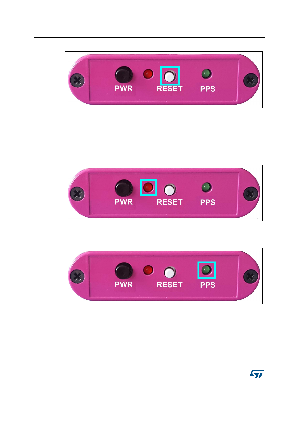
Figure 3. Reset button . . . . . . . . . . . . . . . . . . . . . . . . . . . . . . . . . . . . . . . . . . . . . . . . . . . . . . . . . . . . . 8
Figure 4. Power LED indicator . . . . . . . . . . . . . . . . . . . . . . . . . . . . . . . . . . . . . . . . . . . . . . . . . . . . . . . 8
Figure 5. PPS LED indicator . . . . . . . . . . . . . . . . . . . . . . . . . . . . . . . . . . . . . . . . . . . . . . . . . . . . . . . . 8
Figure 6. USB/UART connector . . . . . . . . . . . . . . . . . . . . . . . . . . . . . . . . . . . . . . . . . . . . . . . . . . . . . . 9
Figure 7. UART to USB path through the FTDI converter . . . . . . . . . . . . . . . . . . . . . . . . . . . . . . . . . . 9
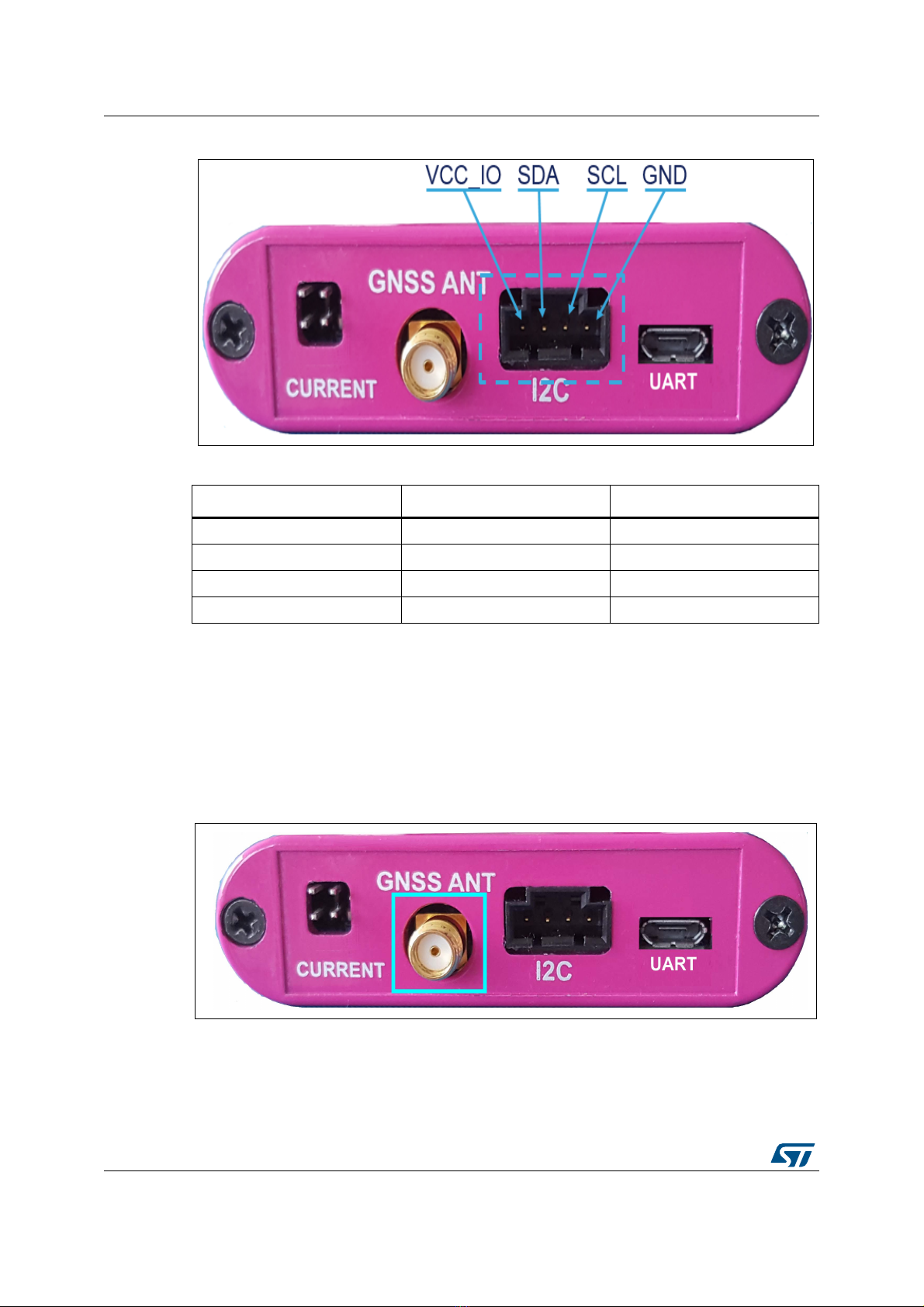
Figure 8. I2C connector . . . . . . . . . . . . . . . . . . . . . . . . . . . . . . . . . . . . . . . . . . . . . . . . . . . . . . . . . . . 10
Figure 9. GNSS SMA connector . . . . . . . . . . . . . . . . . . . . . . . . . . . . . . . . . . . . . . . . . . . . . . . . . . . . 10
Figure 10. Current measurement connector . . . . . . . . . . . . . . . . . . . . . . . . . . . . . . . . . . . . . . . . . . . . 11
Figure 11. Pins placement in the current measurement connector . . . . . . . . . . . . . . . . . . . . . . . . . . . 12
Figure 12. New Session panel . . . . . . . . . . . . . . . . . . . . . . . . . . . . . . . . . . . . . . . . . . . . . . . . . . . . . . . 13
Figure 13. Edit Session Configuration button . . . . . . . . . . . . . . . . . . . . . . . . . . . . . . . . . . . . . . . . . . . 13
Figure 14. Configuration Device panel. . . . . . . . . . . . . . . . . . . . . . . . . . . . . . . . . . . . . . . . . . . . . . . . . 15
Figure 15. Configuration Session panel with one device added . . . . . . . . . . . . . . . . . . . . . . . . . . . . . 16
Figure 16. Port connections active. . . . . . . . . . . . . . . . . . . . . . . . . . . . . . . . . . . . . . . . . . . . . . . . . . . . 16
Figure 17. NMEA output view . . . . . . . . . . . . . . . . . . . . . . . . . . . . . . . . . . . . . . . . . . . . . . . . . . . . . . . 17
Figure 18. NMEA view panel . . . . . . . . . . . . . . . . . . . . . . . . . . . . . . . . . . . . . . . . . . . . . . . . . . . . . . . . 17
Figure 19. Block diagram . . . . . . . . . . . . . . . . . . . . . . . . . . . . . . . . . . . . . . . . . . . . . . . . . . . . . . . . . . . 18

UM2335 Rev 2 5/20
UM2335 Features
19
1 Features
EVB-LIV3x has the following features:
USB Power Supply
Internal backup battery placing (battery not provided)
Push buttons to switch ON and OFF
Current measurement connector
Reset button
UART by USB connector
I2C slave connector
PPS output LED
Power output LED

EVB-LIV3x general presentation UM2335
6/20 UM2335 Rev 2
2 EVB-LIV3x general presentation
EVB-LIV3x kit is composed of several elements:
EVB-LIV3x evaluation board
GNSS active antenna
1 USB cable

UM2335 Rev 2 7/20
UM2335 Interfaces
19
3 Interfaces
EVB-LIV3x offers different interfaces to the user:
ON/OFF button
Reset button
µUSB use for interface with UART of Teseo-LIV3x
Supply by USB (5V)
GNSS antenna input
LED indicators
3.1 Power by USB
A micro USB connector (Figure 1) allows supplying the board identified in blue below.
Figure 1. Power input
3.2 ON/OFF switch
Figure 2. ON/OFF switch
When button (Figure 2) is lifted if the user presses the ON/OFF switch the board turns ON
and power LED turns on.
When the ON/OFF switch is lifted, VBAT is connected to GND, the board is switched OFF.
3.3 Reset
A reset button (Figure 3) is present on the front case panel and it resets the Teseo-LIV3x
module.

Interfaces UM2335
8/20 UM2335 Rev 2
Figure 3. Reset button
3.4 LED indicators
EVB-LIV3x offers two LED Indicators as shown below.
The PWR Red LED (Figure 4) indicator shows whether the unit is ON (led is turned on) or
OFF (led is turned off).
Figure 4. Power LED indicator
The PPS Green LED (Figure 5) indicator blinking every second indicates that Teseo-
LIV3x is up and running;
Figure 5. PPS LED indicator
3.5 UART by USB
UART interface (Figure 6) is provided via USB connector.

UM2335 Rev 2 9/20
UM2335 Interfaces
19
Figure 6. USB/UART connector
UART interface is used to trace NMEA messages and to upload the binary file on system.
Before using the UART/USB bridge FT232RQ the Virtual COM Port (VCP) driver needs to be
installed. It can be downloaded from FTDIChip web site.
The VCP device drivers allow the FT232RQ device on EVB-LIV3x to appear on the PC's
application software as a standard COM port. The application software running on the PC
accesses the FT232RQ device as it would access a standard hardware COM port
configured as shown in Table 1. However, the actual data transfer between the PC and the
FT232RQ device is performed over the USB interface as shown in Figure 7.
Figure 7. UART to USB path through the FTDI converter
3.6 I2C interface
The 4-pin connector (CN302) provides I2C bus signal and power supply as shown in
Figure 8.
Table 1. EVB-LIV3x – UART Configuration Parameters
Baud rate Data Bits Stop Bits Parity Handshake
9600 Baud 8 Bits 1 Bit none none

Interfaces UM2335
10/20 UM2335 Rev 2
Figure 8. I2C connector
This header allows connection of an external I2C-Master-device to the Teseo-LIV3x.
Teseo-LIV3x always acts as slave on I2C-bus.
3.7 GNSS input antenna
GNSS input Figure 9 is available through a SMA female connector.
Figure 9. GNSS SMA connector
Passive or active antenna can be used on EVB-LIV3x.
The DC power supply for active antenna is 3V3 with current limitation in case of short circuit.
Note: Please use a DC blocker for passive or simulator connected to EVB-LIV3x.
Table 2. I2C connector pin description
Pin Connector Signal Comment
1 VCC_IO 3V3 power supply
2 I2C_SDA I2C Data line
3 I2C_SCL I2C clock line
4 GND Ground connection

UM2335 Rev 2 11/20
UM2335 Interfaces
19
3.8 Current measurement connector
EVB-LIV3x provides a connector (Figure 10) to evaluate current consumption.
Figure 10. Current measurement connector
Table 3. Current measurement connector pin description
Pin Connector Signal Comment
1 VCC power supply
2 PMA Vcc measure point
3 VBATT power supply
4 PMB Vbatt measure point

Current measurement process UM2335
12/20 UM2335 Rev 2
4 Current measurement process
To measure the current consumption of Teseo-LIV3x in the different operating modes based
on the pins placement as shown is Figure 11, these steps should be followed:
Figure 11. Pins placement in the current measurement connector
1. Connect a true-rms voltmeter to:
– Vcc (pin-1) and PMA (pin-2)
– Vbat (pin-3) and PMB (pin-4)
2. Wait 15 minutes to download all GNSS orbital data.
3. Read the voltage (and average if necessary) the current value is done by the following
conversion.
–VCC 1 mV equals 1 mA
– VBATT 100 mV equals 1 mA
Note: Perform the test with good signals and clear sky view to ensure that the receiver can acquire
the satellite signals.
To measure the current while in Standby mode with EVB- LIV3x, follow these steps:
a) With antenna connected, powered up, put EVB-LIV3x into Standby mode by
sending $PSTMFORCESTANDBY command.
b) Perform steps 1, 2 and 3.
To measure the current while acquiring GNSS satellites with EVB- LIV3x, follow these steps:
a) Disconnect antenna and powered up EVB-LIV3x
b) Perform steps 1, 2 and 3
Note: The acquisition current will vary based on the number of constellations you have configured
the firmware to acquire, so please take note of that when taking and comparing
measurements.

UM2335 Rev 2 13/20
UM2335 Teseo Suite connection
19
5 Teseo Suite connection
Install and start Teseo Suite, and follow the directions below.
5.1 Getting started with the Teseo-Suite
When the application starts, Teseo-Suite opens the configuration session panel, as shown
in Figure 12 below, to allow the user to add the EVB-LIV3x.
Then enter a session name to enable the “Add Device” button.
Figure 12. New Session panel
If the “Configuration Session” panel is not opened, two ways either can be followed as
shown in
Figure 13
:
1. Go to the "File" menu and select "New Session"
2. Click the "Edit Session Configuration" button.
Figure 13. Edit Session Configuration button

Teseo Suite connection UM2335
14/20 UM2335 Rev 2
5.2 Add/Delete Device
In the "Configuration Session" panel, you can add/remove EVB-LIV3x devices in the work
session and monitor the exisiting ones.
Pressing the button "Add Device" brings up the "Device Configuration" form, as shown in
Figure 14.
Set the hardware type ‘STA8090’ value.
Select the Control port and choose the parameters of the serial connection as in Table 1
On the Control port, the user can select the NMEA protocol
Press the “OK” button to create the device.

UM2335 Rev 2 15/20
UM2335 Teseo Suite connection
19
Figure 14. Configuration Device panel
When selecting the port name, the Teseo-Suite provides an enumeration of all the COM
ports available even if these COM ports are already used by another application.
Please note that the protocol of the device and its name cannot be changed once the “OK”
button has been clicked.
To delete a device from the session, press the corresponding delete button in the “Delete
Device” column from the "Configuration Session" form.

Teseo Suite connection UM2335
16/20 UM2335 Rev 2
Figure 15. Configuration Session panel with one device added
The button “Delete All” removes all the devices of the current session.
5.3 Connect or disconnect Control Port
The Control port defined when a device has been added can be opened. If a port is defined,
the corresponding checkbox is enabled. Selecting the checkboxes in the “Connect Ctrl port”
column enables the corresponding connection buttons, as shown in Figure 15 above.
Click the “Connect” (Electrical Plug) button to open the selected ports, and a red X shows
up, as shown in Figure 16 below.
Figure 16. Port connections active
Open the NMEA output window to confirm the proper NMEA output using the button shown
in Figure 17.

Board general view UM2335
18/20 UM2335 Rev 2
6 Board general view
6.1 Default jumper configuration
J300 : leave open
J302 : 2-3 : no use of VCC_RF to optimize Teseo-LIV3x current
J303 : 2-3 : VCC_IO=3.3V
J400 : 2-3 : same reason as J302
J500 : 1-2 : use 2.1V to supply Teseo-LIV3x in order to optimize current consumption
6.2 Block diagram overview
Figure 19. Block diagram

UM2335 Rev 2 19/20
UM2335 Revision history
19
7 Revision history
Table 4. Document revision history
Date Revision Changes
28-Mar-2018 1 Initial release.
05-Dec-2019 2 Minor text changes.

UM2335
20/20 UM2335 Rev 2
IMPORTANT NOTICE – PLEASE READ CAREFULLY
STMicroelectronics NV and its subsidiaries (“ST”) reserve the right to make changes, corrections, enhancements, modifications, and
improvements to ST products and/or to this document at any time without notice. Purchasers should obtain the latest relevant information on
ST products before placing orders. ST products are sold pursuant to ST’s terms and conditions of sale in place at the time of order
acknowledgement.
Purchasers are solely responsible for the choice, selection, and use of ST products and ST assumes no liability for application assistance or
the design of Purchasers’ products.
No license, express or implied, to any intellectual property right is granted by ST herein.
Resale of ST products with provisions different from the information set forth herein shall void any warranty granted by ST for such product.
ST and the ST logo are trademarks of ST. For additional information about ST trademarks, please refer to www.st.com/trademarks.All other
product or service names are the property of their respective owners.
Information in this document supersedes and replaces information previously supplied in any prior versions of this document.
© 2019 STMicroelectronics – All rights reserved
This manual suits for next models
2
Table of contents
Other ST Motherboard manuals

ST
ST EVAL-L9960 User manual

ST
ST NUCLEO-8S207K8 User manual

ST
ST STM32L4R9I-EVAL User manual

ST
ST STEVAL-USBPD45H User manual

ST
ST STEVAL-PCC008V1 User manual

ST
ST L5965 User manual

ST
ST AEK-MOT-TK200G1 User manual

ST
ST STM8/128-EVAL User manual

ST
ST STM3241G-EVAL User manual

ST
ST M24LR-DISCOVERY User manual

ST
ST EnFilm EFL1K0AF39 User manual

ST
ST STM3240G-EVAL User manual

ST
ST EVALKITSTKNX User manual

ST
ST STEVAL-IPMM10B User manual

ST
ST STM32CubeH7 User manual

ST
ST STMPE821 User manual

ST
ST STEVAL-ISB042V1 User manual

ST
ST VIPower VIPer22A-E Installation and operating instructions

ST
ST STM32L073Z-EVAL User manual

ST
ST BlueNRG-LP User manual