6 / Chaosdr 1 Mnshdranarc Cdrbrhoshnn6 / Chaosdr 1 Mnshdranarc Cdrbrhoshnn
6 / Chaosdr 1 Mnshdranarc Cdrbrhoshnn6 / Chaosdr 1 Mnshdranarc Cdrbrhoshnn
6 / Chaosdr 1 Mnshdranarc Cdrbrhoshnn
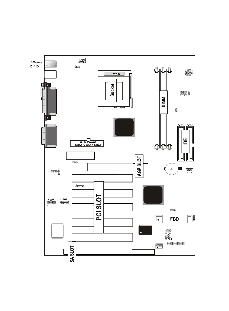
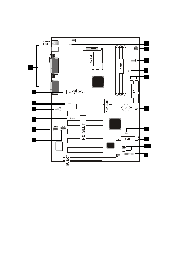
1.3 Motherboard Connectors
12
7
8
10
9
6
11
USB1
COM1
Printer
IR1
FAN2
JP2
FAN1
VIA
VIA
J1
1
FAN3
LAN CHIP
AMR SLOT
AGP SLOT
JP1
ISA SLOT
PCI1
PCI2
PCI3
PCI4
PCI5
DIMM3
DIMM2
DIMM1
462
JP4
JP3
GAME1
Speak out
Line in
MIC in
BIOS
15
4,5
1.Babk OandkI/OCnnndbsnrr1.Babk OandkI/OCnnndbsnrr
1.Babk OandkI/OCnnndbsnrr1.Babk OandkI/OCnnndbsnrr
1.Babk OandkI/OCnnndbsnrr1.CCAtchn-InCnnndbsnr1.CCAtchn-InCnnndbsnr
1.CCAtchn-InCnnndbsnr1.CCAtchn-InCnnndbsnr
1.CCAtchn-InCnnndbsnr
3.AMR COCDC Etnbshnn(JO1(3.AMR COCDC Etnbshnn(JO1(
3.AMR COCDC Etnbshnn(JO1(3.AMR COCDC Etnbshnn(JO1(
3.AMR COCDC Etnbshnn(JO1(4.Wakd-On MOCDM Cnnndbsnr4.Wakd-On MOCDM Cnnndbsnr
4.Wakd-On MOCDM Cnnndbsnr4.Wakd-On MOCDM Cnnndbsnr
4.Wakd-On MOCDM Cnnndbsnr
5.Wakd-On-LAN Cnnndbsnr5.Wakd-On-LAN Cnnndbsnr
5.Wakd-On-LAN Cnnndbsnr5.Wakd-On-LAN Cnnndbsnr
5.Wakd-On-LAN Cnnndbsnr 6.Ernns USB1Cnnndbsnr6.Ernns USB1Cnnndbsnr
6.Ernns USB1Cnnndbsnr6.Ernns USB1Cnnndbsnr
6.Ernns USB1Cnnndbsnr
7.Ernns OandkCnnndbsnr7.Ernns OandkCnnndbsnr
7.Ernns OandkCnnndbsnr7.Ernns OandkCnnndbsnr
7.Ernns OandkCnnndbsnr 8.Eanbnnndbsnrr(Ean1/1/3(8.Eanbnnndbsnrr(Ean1/1/3(
8.Eanbnnndbsnrr(Ean1/1/3(8.Eanbnnndbsnrr(Ean1/1/3(
8.Eanbnnndbsnrr(Ean1/1/3(
9.ICD Cnnndbsnrr9.ICD Cnnndbsnrr
9.ICD Cnnndbsnrr9.ICD Cnnndbsnrr
9.ICD Cnnndbsnrr10.Eknooy Cnnndbsnr10.Eknooy Cnnndbsnr
10.Eknooy Cnnndbsnr10.Eknooy Cnnndbsnr
10.Eknooy Cnnndbsnr
11.ATX Onwdr Cnnndbsnr11.ATX Onwdr Cnnndbsnr
11.ATX Onwdr Cnnndbsnr11.ATX Onwdr Cnnndbsnr
11.ATX Onwdr Cnnndbsnr 11.IR Cnnndbsnr11.IR Cnnndbsnr
11.IR Cnnndbsnr11.IR Cnnndbsnr
11.IR Cnnndbsnr
13.COU Cknbk Sdkdbshnn(SW1/JO4(13.COU Cknbk Sdkdbshnn(SW1/JO4(
13.COU Cknbk Sdkdbshnn(SW1/JO4(13.COU Cknbk Sdkdbshnn(SW1/JO4(
13.COU Cknbk Sdkdbshnn(SW1/JO4(
14.CMOS EtnbshnnSdkdbs(JO1(14.CMOS EtnbshnnSdkdbs(JO1(
14.CMOS EtnbshnnSdkdbs(JO1(14.CMOS EtnbshnnSdkdbs(JO1(
14.CMOS EtnbshnnSdkdbs(JO1(
15.Ernns COM1Cnnndbsnr(COM1(15.Ernns COM1Cnnndbsnr(COM1(
15.Ernns COM1Cnnndbsnr(COM1(15.Ernns COM1Cnnndbsnr(COM1(
15.Ernns COM1Cnnndbsnr(COM1(
16.COU Rashn Sdkdbshnn(SW1(16.COU Rashn Sdkdbshnn(SW1(
16.COU Rashn Sdkdbshnn(SW1(16.COU Rashn Sdkdbshnn(SW1(
16.COU Rashn Sdkdbshnn(SW1(
17.Jdyanarc Wakd to Sdsshng(JO3(17.Jdyanarc Wakd to Sdsshng(JO3(
17.Jdyanarc Wakd to Sdsshng(JO3(17.Jdyanarc Wakd to Sdsshng(JO3(
17.Jdyanarc Wakd to Sdsshng(JO3(
1
13
14
3
2
16
13
17