iFixit Mac Mini Model A1347 User manual
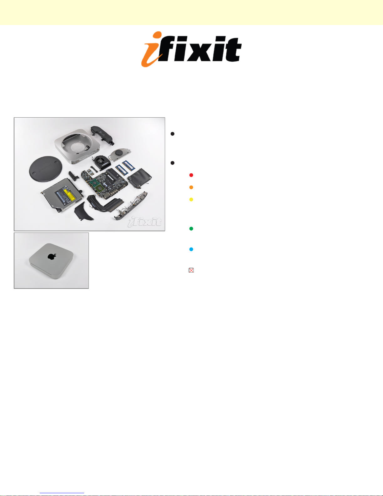
Mac Mini Model A1347 Teardown
Step 1 -
Well folks, after much clamor, it seems the engineers at
Apple have finally included an HDMI port in an actual
Apple product.
Notable Tech Specs:
2.4 or 2.66 GHz Intel Core 2 Duo processor
2 GB of RAM (expandable up to 8 GB)
NVIDIA GeForce 320M graphics processor with
256MB of shared DDR3 SDRAM (the same as
the most recent MacBook)
HDMI port with support for up to 1920-by-1200
resolution
AirPort Extreme 802.11n Wi-Fi wireless
networking
SD card slot
Mac Mini Model A1347 Teardown
© 2010 iFixit — CC BY-NC-SA www.iFixit.com Page 1 of 13

Step 2
Contents of box:
Mac Mini
HDMI to DVI adapter
Power cord
Step 3
Departing from previous generations, the Mini's unibody
top enclosure is machined from a single block of
aluminum.
Measuring 1.4 x 7.7 x 7.7 inches and weighing only 3
lbs, this is truly one for the books.
The black logo and other accents match quite nicely
with the styling of Apple's iPad and recent iMacs.
Congrats, Mini, you're no longer the black sheep of the
family!
The model number for this new unit is A1347.
Mac Mini Model A1347 Teardown
© 2010 iFixit — CC BY-NC-SA www.iFixit.com Page 2 of 13

Step 4
The Mini's new port layout is indeed surprising:
AC power in
Built-in 10/100/1000BASE-T ethernet
Firewire 800
HDMI
Mini DisplayPort
Four USB 2.0 ports, down one from the previous
Mac Mini
SD card slot
Step 5
In comparison to the Mac Mini model A1176, the Mid
2010 is thinner and wider.
There is a definite difference in height between the Mid
2010 and previous iterations.
Mac Mini Model A1347 Teardown
© 2010 iFixit — CC BY-NC-SA www.iFixit.com Page 3 of 13

Step 6
With a simple counter-clockwise twist, the black access
plate can be removed for easy RAM and fan access.
Gone are the days of the putty knife...you
will be missed old friend...
Step 7
Much like many other new Apple products, removing
the RAM is quite feasible this time around.
This little guy comes with two SO-DIMM slots capable
of supporting up to 8GB of RAM.
Our base unit came strapped with two gigs of RAM.
Mac Mini Model A1347 Teardown
© 2010 iFixit — CC BY-NC-SA www.iFixit.com Page 4 of 13
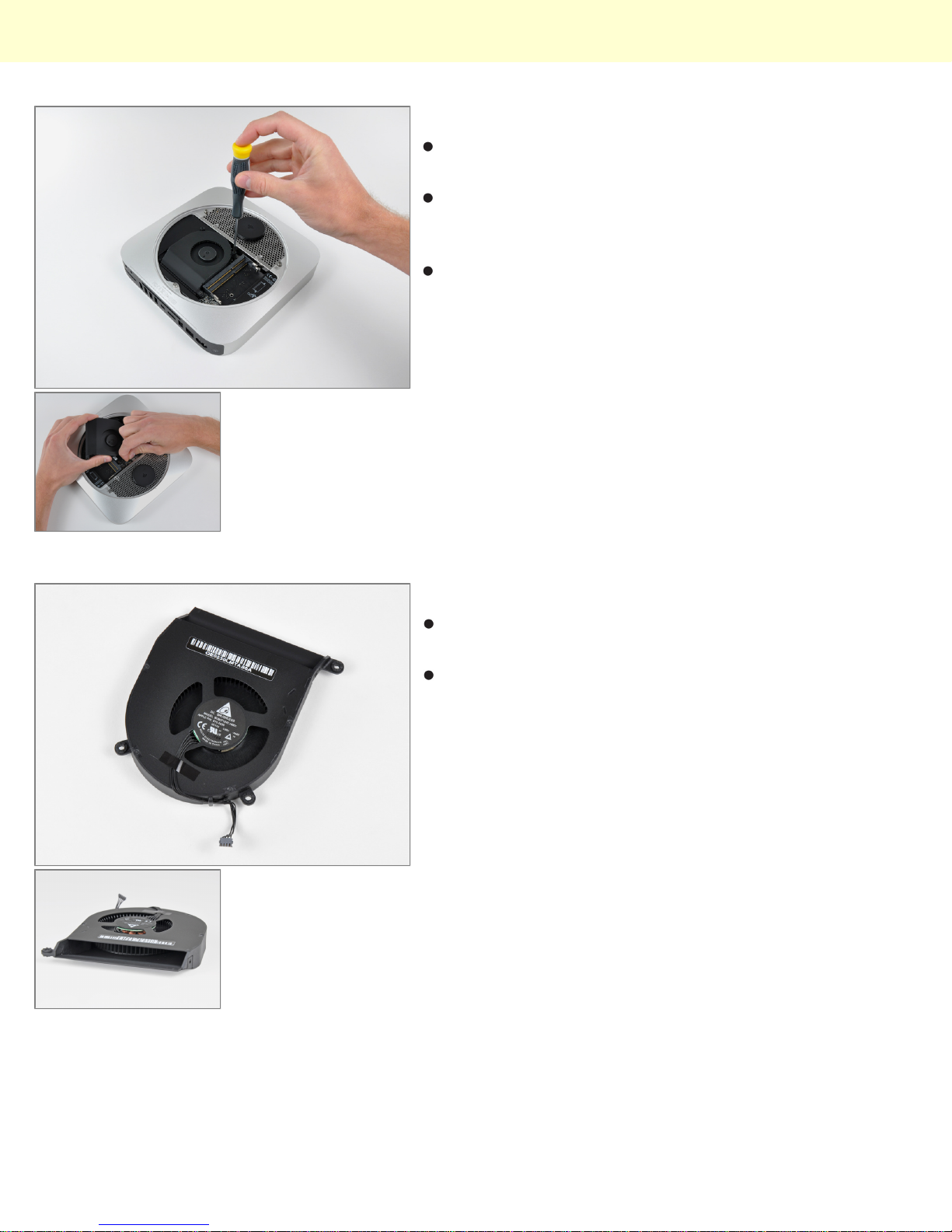
Step 8
After removing two screws, the fan can be lifted out to
access its power connector.
The connectors inside this machine look pretty
consistent with those found in Apple's current product
lineup. Nothing too new here.
All three fan screws are isolated with rubber dampers; a
feature not seen on older apple machines. Low noise
and vibration are big selling points for Apple these
days, and the new Mini's idle emission of 14 dB is a
testament to those design goals.
Step 9
Like previous generations, the new Mini is cooled by a
single brushless fan.
The extremely high blade density of the blower pushes
a good amount of air while keeping noise at a minimum.
Mac Mini Model A1347 Teardown
© 2010 iFixit — CC BY-NC-SA www.iFixit.com Page 5 of 13
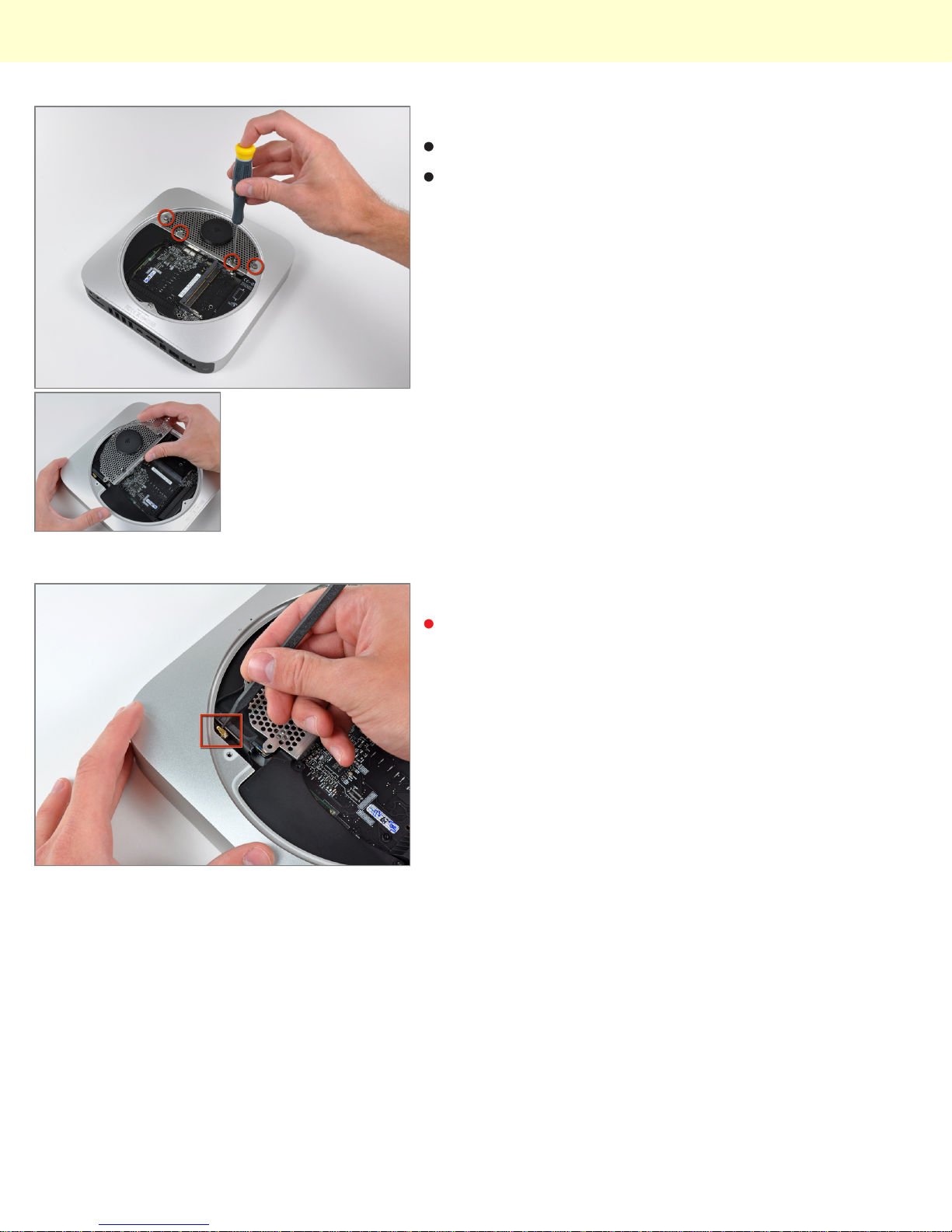
Step 10
The Wi-Fi antenna plate is held in place by four screws.
After a good deal of wiggling, the antenna plate can be
slid out from under the lip of the outer case.
Step 11
The top Wi-Fi antenna connector is hidden underneath
the antenna plate near the hard drive connector.
Mac Mini Model A1347 Teardown
© 2010 iFixit — CC BY-NC-SA www.iFixit.com Page 6 of 13
Step 12
Removing the cowling gives access to various
connectors on the logic board:
Hard drive flex cable
Optical drive flex cable (in the server model, this
is where the second hard drive flex cable is)
Thermal sensor cables
Infrared board cable
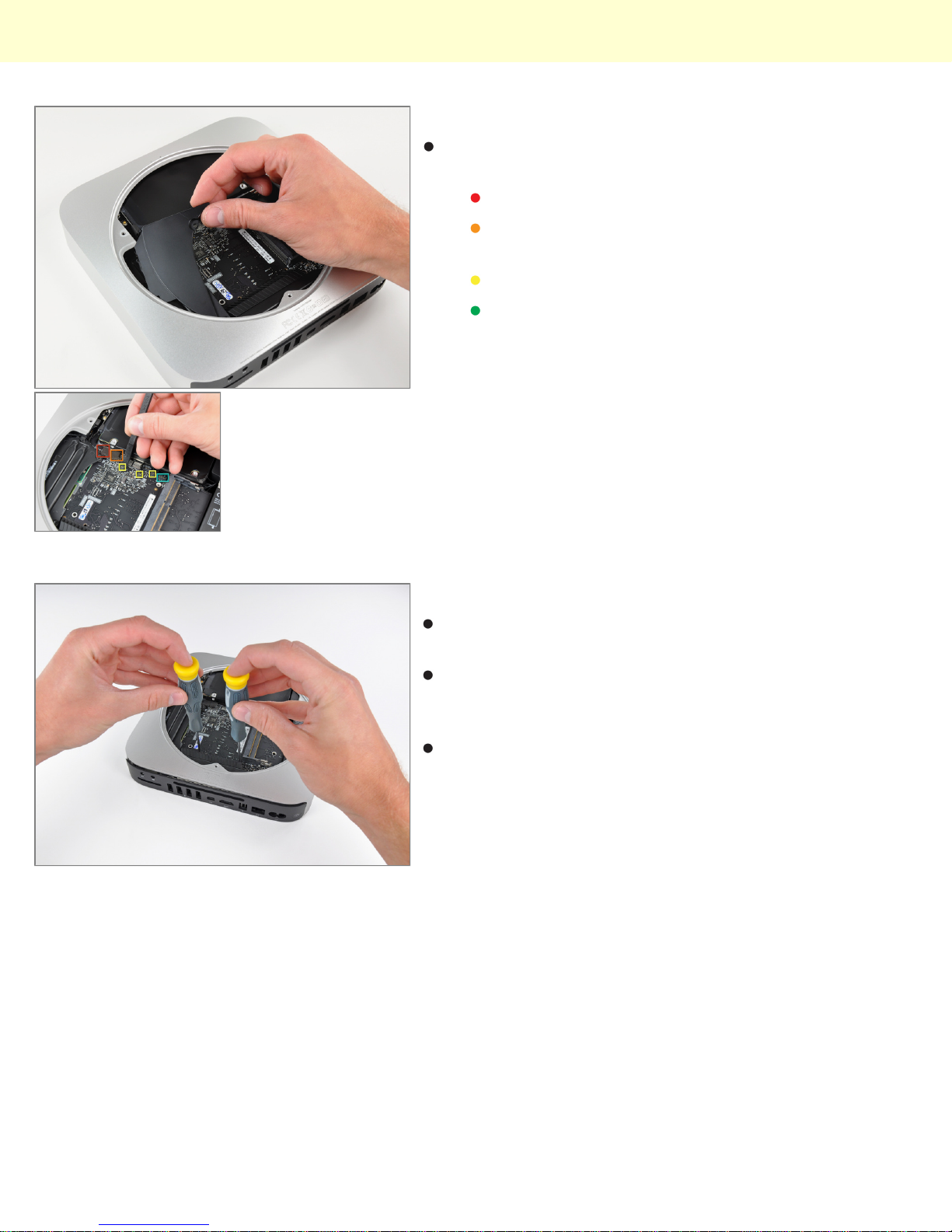
Step 13
Behold, iFixit's specialized Mac Mini Mid 2010 logic
board removal tool!
There are two blind holes in the case of the Mini that
are meant for the ends of Apple's u-shaped logic board
removal tool.
Being the shadetree mechanics that we are, we
decided to circumvent the special Apple tool in favor of
something that works just fine while keeping extra
dollars out of Mr. Jobs' pockets.
Mac Mini Model A1347 Teardown
© 2010 iFixit — CC BY-NC-SA www.iFixit.com Page 7 of 13

Step 14
Before completely sliding out the logic board assembly,
the power supply connector must be disconnected.
After disconnecting the power cable, the logic board
assembly slides right out.
Step 15
The top and bottom of the logic board and I/O frame
assembly.
In using unibody construction, Apple had to get creative
with the placement of the antennas. Two auxiliary
antennas are the square steel components seen at
both ends of the I/O frame.
Mac Mini Model A1347 Teardown
© 2010 iFixit — CC BY-NC-SA www.iFixit.com Page 8 of 13

Step 16
Two screws secure the speaker assembly to the logic
board.
The Mini's 3/8" woofer dome won't be popping ear
drums anytime soon.
Step 17
Next to where the speaker was located, we find the
AirPort Extreme card.
The Mac Mini Mid 2010 has 802.11n Wi-Fi wireless
networking, as well as Bluetooth 2.1 with Enhanced
Data Rate technology.
After disconnecting the remaining two antenna
connectors and its data cable, the AirPort card can be
easily removed from the logic board.
Mac Mini Model A1347 Teardown
© 2010 iFixit — CC BY-NC-SA www.iFixit.com Page 9 of 13
Step 18
A couple of spring-loaded T8 Torx screws secure the
oddly shaped heat sink to the processors.
In keeping with its space saving design, the fins
directing air toward the vent hole are slanted to allow
for better fan placement.
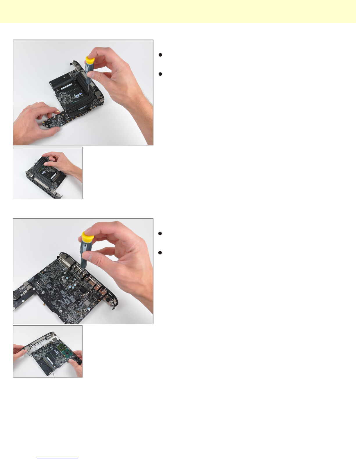
Step 19
The I/O frame is held to the logic board by a few T6
Torx screws.
The two I/O bezel antennas are more visible in this
picture. The long antenna wires are grounded
periodically along their length, presumably for better
signal transmission to the important part - the antennas
themselves.
Mac Mini Model A1347 Teardown
© 2010 iFixit — CC BY-NC-SA www.iFixit.com Page 10 of 13
Other manuals for Mac Mini Model A1347
1
Table of contents


