iFlow iFLH-14000W User manual
iFLOW HVAC INC. www.iflowhvac.com
iNTELLIGENT SMART IoT TECHNOLOGIES
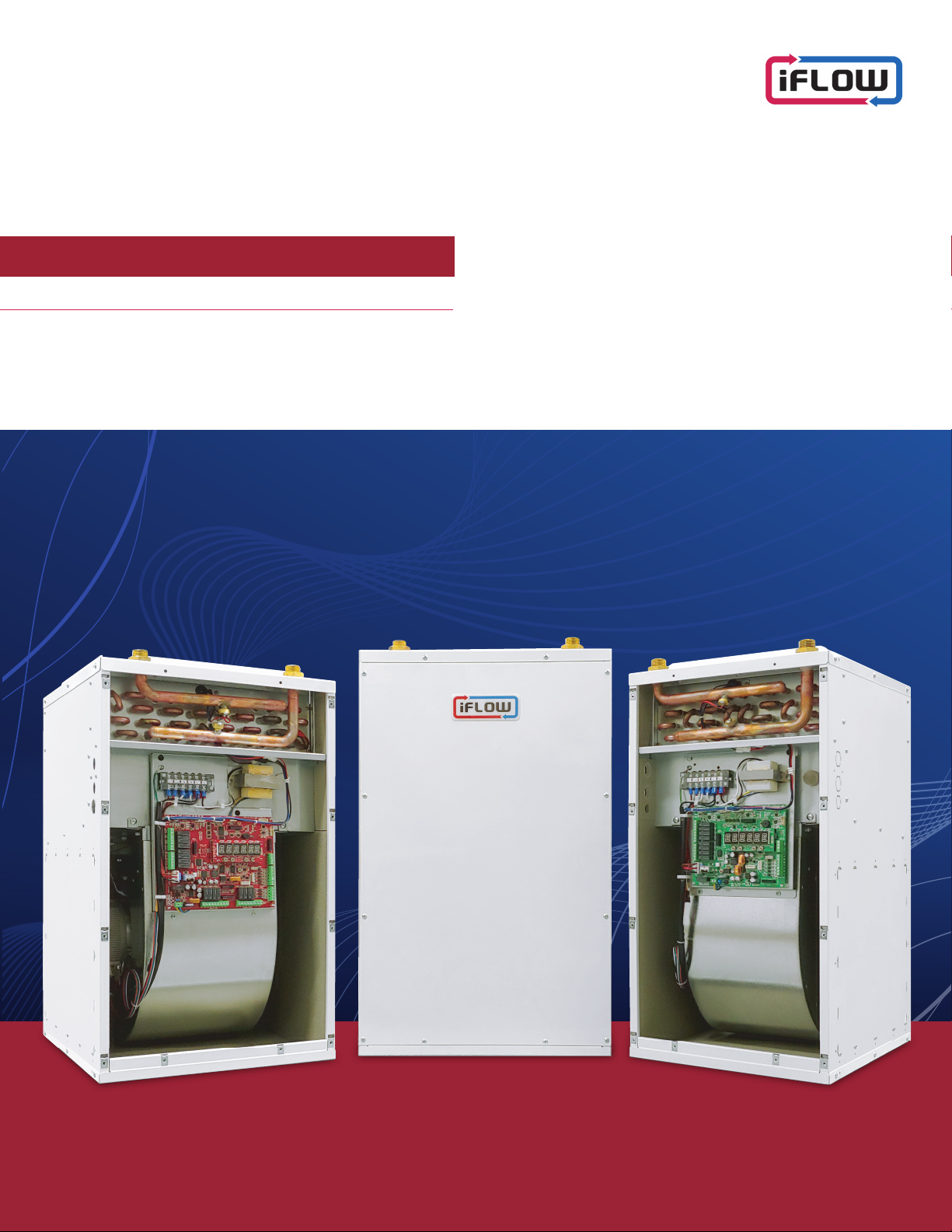
iFLOW HYDRONIC AIR HANDLER
NEW GENERATION OF HEATING &COOLING
iFLOW AHU MANUAL
WiFi & ZONING
Model
iFLH-14000W
iFLH-16000W
iFLH-18000W
iFLH-16000D
iFLH-18000D
iFLH-18000Q
iFLOW HVAC INC.
www.iflowhvac.com

iFLOW HVAC INC. www.iflowhvac.com
2
Introduction
1. Introduction Safety ………………………………………………………………………………………………………………………………………………………… 3
2. Summary of Air Handler Components …………………………………………………………………………………………………………………………… 3
3. Installer’s checklist ………………………………………………………………………………………………………………………………………………………… 3
Product Description
1. Components ………………………………………………………………………………………………………………………………………………………………… 4
2. Standard features and benefits ……………………………………………………………………………………………………………………………………… 5
3. Equipment selection and sizing ……………………………………………………………………………………………………………………………………… 6
4. Suitable applications (choosing the right heat source) …………………………………………………………………………………………………… 9
Installation
1. Location requirements and clearances ………………………………………………………………………………………………………………………… 10
2.Dimensions ………………………………………………………………………………………………………………………………………………………………… 10
3. Installation examples …………………………………………………………………………………………………………………………………………………… 11
4. Water heater/ boiler piping …………………………………………………………………………………………………………………………………… 11
5. Domestic piping ……………………………………………………………………………………………………………………………………………………… 11
6. Installing the iFLOW air handler with a tankless/tank water heater ……………………………………………………………………… 12
7. Electrical requirements and making connections ……………………………………………………………………………………………………… 12
8. Temperature sensors ……………………………………………………………………………………………………………………………………………… 12
9. Installing the iFLOW air handler with a Navien tankless water heater …………………………………………………… 13
10. Zone damper ……………………………………………………………………………………………………………………………………………………………… 13
11. WiFi Module connect to iFLOW control boards ………………………………………………………………………………………………………… 13
Start-Up
1. Procedure ……………………………………………………………………………………………………………………………………………………………………… 14
2. Flushing the heat exchanger ………………………………………………………………………………………………………………………………………… 14
3. Sequence of operation ………………………………………………………………………………………………………………………………………………… 14
Service and Maintenance
1. Maintenance …………………………………………………………………………………………………………………………………………………………… 20
2. Checking temperature sensors …………………………………………………………………………………………………………………………………… 20
3. Wiring diagrams ………………………………………………………………………………………………………………………………………………………… 21
4. Ladder diagram …………………………………………………………………………………………………………………………………………………………… 28
Troubleshooting
1. Fault codes and explanations …………………………………………………………………………………………………………………………………… 29
2. Problems and solutions …………………………………………………………………………………………………………………………………………… 31
3. Component assembly diagram and parts list …………………………………………………………………………………………………………… 32
4. Installation diagram …………………………………………………………………………………………………………………………………………………… 40
Warranty and Contact Information
1. Warranty ……………………………………………………………………………………………………………………………………………………………………… 48
2. Contact information …………………………………………………………………………………………………………………………………………………… 48
Table of Contents

iFLOW HVAC INC. www.iflowhvac.com
WARNING
This Air Handler Unit (AHU) is not intended for installation in a
unconditioned space where the potential may exist for the water
and/or drain lines to freeze.
3
1. Introduction Safety
Ensure the instructions and requirements provided in this manual are
read and understood before installation. Failure to comply with these
instructions can cause product and property damage, serious injury
or death.
Pay attention to the following safety symbols and words:
DANGER
Indicates an imminently hazardous situation, which if not
avoided, will result in death or serious injury.
WARNING
This product can expose you to chemicals including lead,
lead compounds, and carbon bisulfide which are known to the
State of California to cause cancer and birth defects or other
reproductive harm. For more information, go to
www.P65Warnings.ca.gov.
CAUTION
Indicated a potentially hazardous situation, which if not
avoided, may result in minor or moderate injury. It is also used
to alert against unsafe practices and hazards involving property
damage.
• Be sure to bleed all air from all system components and piping prior
to start-up.
• It is recommended to install purge valves between the air handler
and water heater’s isolation valves.
• If connected to domestic piping creating an open system, make
sure all piping, components, and solder are lead-free and approved
for potable-use.
CAUTION
Return air openning shall not be installed
on the back side of unit.
IMPORTANT
The maximum ambient temperature must
not exceed 122℉ (50℃)
• Ensure fan assembly is clear of any obstruction
• Check that air filter is installed upstream of air conditioning coil.
• If the appliance is installed with air conditioning,the A/C refrigerant
charge and system operation must be verified by a certified/ licensed
mechanic prior to commissioning.
2. Summary of air handler
The iFLOW hydronic air handlers are designed to deliver the highest
performance rating of any air handler regardless of the hot water
source. This unique hydronic furnace is built for use in residential and
commercial applications.
CAUTION
The air handler must be installed such that electrical components
are away from water (spraying, splashing, etc.) during operation and
service.
IMPORTANT
A field fabricated auxiliary drain pan with a drain pipe connection is
recommended in all configurations.
Introduction
3. Installer’s checklist
iFLOW HVAC INC. www.iflowhvac.com
4
1) Components
Cabinet:
All cabinets are made of high quality, and durable heavy gauge
galvanized steel. The inside of the cabinet is fully insulated with ½”
polyethylene sheets. This prevents moisture and mold growth, as well
as unwanted heat loss due to an R-Value. The smaller cabinet size
and shape is designed to maximize installation flexibility.
Heating Coils:
All iFLOW heating coils are constructed of potable, water-grade
copper for use in plumbing systems. Lead-Free solder has been used
for assembly on all components. All coils and internal piping conform
to ASTM B-68, ASTM B-88 and/or B-743 standards. Carefully
engineered, high-density aluminium fins allow for maximum heat
transfer across smaller coils. This provides warmer, more comfortable
heating with lower air flow for minimal operating noise.
Fan Motor:
All iFLOW air handlers are equipped with variable speed ECM
motors. This allows for separate heating, cooling, and continuous run
speeds. They reduce electrical-use and are dynamically balanced
for extra quiet operation. Blowers are mounted with four screws on
rails for easy removal and service. Multi-directional motors allow for
mounting in any direction.
Circulating Pump:
All air handlers require a field supplied single speed or 3-speed pump,
to be controlled by the iFLOW circulator control. This the speed of the
pump increases or decreases depending on the information provided
by the temperature sensors. The pump also provides maximum
performance when used in conjunction with an instantaneous water
heater or a storage-type water heater.
Check Valve:
A spring-loaded check valve must be installed either with the field-
supplied pump or externally to prevent the by passing of water to the
appliance.
Multi-Function Control Board:
This intelligent control board comes factory installed. No dip
switches are required or included with the iFLOW control board.
Easy programming allows for user-friendly startup and service/
maintenance. Some of the parameters the user is able to configure
are: heating output, CFM for heating, cooling and continuous low-
speed fan, outdoor design temperature and circulating pump speed.
Product Description
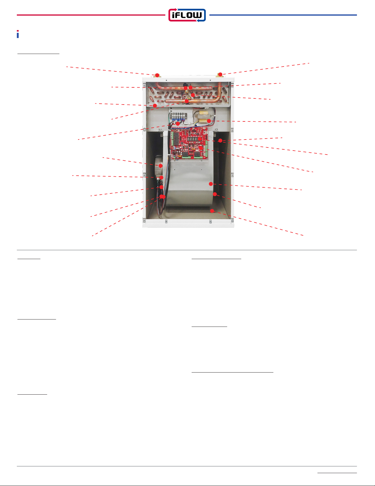
Water Inlet Water Outlet
Supply Air Temp. Sensor
Supply Water Temp. Sensor
Transformer AC24V
Blower Assembly Bracket
Display
Main Control
Blower Assemble
Dehumidier Eva. Temp. Sensor
(Option)
Humidity Sensor
A/C Evap. Air Temp. Sensor
Heat Exchanger Ass'y
(Hydronic Coil)
Return Water Temp. Sensor
Power Terminal
Return Air Temp. Sensor
Blower Motor
Blower Arm & Band
Motor Power Cable
Motor Control Cable

iFLOW HVAC INC. www.iflowhvac.com
2) Standard Features and Benefits:
• Highest performance at 98% efficiency (CAN/CAS P.9-11
Performance Ratings: TPF 0.98)
• Ultra-efficient heat-exchanger design with high-density aluminum
fins
• Offers installation flexibility allowing for up-flow, down-flow or
horizontal applications
• Cost effective and extremely quiet variable speed ECM fan motor /
constant CFM
• Slide-out blower rail assembly for easy maintenance & removal with
4 screws
• 6 fully modulating models: 3 ‘standard duct’ models (S, M, L) & 3
high-static pressure models (S, M, L)
• Easy installation: Lightweight, “one-man job” with Optional EZEE
Plumbing Kit
• Approved for potable water (‘open’) systems with buit-in anti-
stagnation and DHW priority included in the control board
• Air and water supply and return temperature sensors included
• Humidity sensor included for cooling fan speed modulation
• Freeze Protection/ Evaporator Temperature Sensor
• Outdoor temperture sensor included
• Intelligent iFLOW control board
• All models are compatible with mercury or digital thermostats
• Supports the use of two stage and inverter-driven variable speed
cooling equipment
• Accessories are controlled by AC24V power
• LED light indicates alarm, test mode and normal operation
• Auxiliary contacts (dry contact) for boiler or water heater activation
• Bottom or left or right side return air supply
• 0” clearance to combustibles
• Cabinet lined with 1/2” Polyethylene High-Density Insulation
• Cabinet manufactured with heavy gauge galvanized steel and
powder-coated to prevent corrosion
iNTELLIGENT PUMP CONTROL:
• Pump modulation control
• Low flow pump exercise function (Water Circulation / Seize
Protection)
• Low ambient freeze protection
iNTELLIGENT CONTROL:
• Boiler demand control
• Installer & user-friendly interface
• Informative display: error code, temperture, humidity, fan & pump
speed
• Easily configure all parameters smartphone App.
• 22 segment LED indicator / all input & output signals: built-in
programmable and diagnostic control display
• Outdoor reset function / outdoor temperature sensor
• Full modulation a single or two stage settings for heating & cooling
• Humidity control / humidity sensor
• ΔT auto-adjustment air and water (air and water flow control)
• Fan "ON" delay & Fan "OFF" heat purge control
5
• DHW priority & dual mode (heating and DHW)
• High & low limit safety control: air temperature sensor
• Home freeze protection: low ambient temperature sensor
• Evaporator freeze protection: compressor protection
• Virtual termostat mode with the smartphone app
• Smart zoning control (saving gas & hydro)
• Maximize heat pump performance / (AVOID) Peak Time AVOID
Electricity Function
• Hybrid heating system switching control and backup with heat pump
• Communication with NAVIEN Tankless Water Heater
OPTIONS:
• Multi-system central control for building HVAC systems
• Wi-Fi connection with a smartphone (Free app available on iOS and
Android)
• Remotely adjust and monitor operation through web integrated plug-
in control, or directly via a smartphone connection
• All-in-one package (EZEE plumbing kit and stand) for easy
Installation: iFLOW AHU with any TLWH/TWH
Freeze Protection:
iFLOW Air handlers include a freeze protection sensor that will
temporarily disable the outdoor condenser for 5 minutes if the
evaporator coil outlet temperature drops below 40°F/4°C. This will
allow the system to warm up and return back to normal operating
conditions.
To protect the hydronic heating coil from freezing, the pump will
operate for a minimum of 30 seconds. Dirty air filters, oversizing of A/
C equipment, improper A/C installation or poor duct design will also
play a role in the evaporator coil freezing.
Water Circulation / Pump Exercise:
In section 4.2.5.1 Prevention of Stagnation of the 'CAN/CSA-B214-12
Installation Code for Hydronic Heating Systems', it states: "a means
shall be provided to prevent the stagnation of potable water in a
hydronic system by recycling or flushing the contents not less than
once every 24 hours."
The iFLOW controller is defaultset to turn on the circulating pump to
cycle the total volume of potable water in the system, once every 24
hours. This will prevent stagnation and protect the pump from seizing.
There is a test button to verify that this operation is working. The
setting can be adjusted to circulate more frequently if desired.
Alarms:
In the event of a service problem (i.e. temperature sensor failure, low
ambient temperature, cooling lockout, etc.), the iFLOW air handler
will notify the user/owner with an audible alarm and red light. The
alarm on the control board can be silenced by turning the power off
for 5 seconds and then back on.

iFLOW HVAC INC. www.iflowhvac.com
6
Set Back Recovery:
If a programmable thermostat with setback is used or a sudden
increase in temperature is required, the iFLOW intelligent control
board will modulate the air handler to its maximum output to speed
temperature delivery. The next cycle will return to normal operation.
See "Heat Boost Delay" Parameter.
Test Mode:
Entering ‘test mode’ on the controller will allow the technician to test
the iFLOW air handler heating and cooling mode parameters. Once
completed, push the test button again to return to normal operation.
Heating:
The iFLOW air handler will automatically change the fan and pump
speeds to control the temperature output of the unit and cycle-time
length. This will allow the heat output of the air handler to match the
current heat loss of the home. Maximum ‘matching’ performance is
achieved when used in conjunction with the outdoor sensor. This
leads to a longer runtime, providing superior warmth and comfort.
Cooling/Dehumidifying:
The iFLOW air handler uses a modulating blower fan to regulate
humidity levels. The blower fan speed decreases in high humidity
to remove moisture quicker. The blower fan speed increases under
normal conditions to provide optimal cooling. The balance of the two
is always met. Optimal humidity levels result in increased comfort
for the homeowner, and at the same time reduces cooling loads and
operating costs.
3. Equipment selection and sizing
iFLOW air handlers are available in 3 models. Please use the
following charts to determine which best suits the application:
1. Obtain/calculate/determine a proper heat load for the home
2. Determine the inlet water temperature from water heater(or boilder)
3. Determine the duct layout/ available duct size
4. Be sure the system air flow rate matches the air flow rate of the
selected air handler
System Design Resource Note:
From the CAN/CSA-B214-12 Installation Code for Hydronic Heating
Systems, section 4.2.2.1 Heat-source output, it states: "the heat-
source output shall be not less than the heat load indicated in the
system design."
4.2.2.2 Dual-purpose water heater
Model No. Description
Model No. Description WiFi @ IoT Zoning Temperature
Control
iFLH-140000
iSmart
Control No No Room
Thermostat
iFLH-160000
iFLH-180000
iFLH-14000W
iSmart
Control
WiFi
@
Internet/
Paring Mode
No
Room
Thermostat
or
Smart Mode
with
Smartphone
iFLH-16000W
iFLH-18000W
iFLH-16000D
iSmart
Control
WiFi
@
Internet/
Paring Mode
2 Supply
Zone
2 Return
Zone
Room
Thermostat
or
Smart Mode
with
Smartphone
iFLH-18000Q
4 Supply
Zone
4 Return
Zone
Model No. Description
Model No. Format
▶
i F L H - 1 4 0 0 0 0
Function / B: basic, W: WiFi,
D: 2 zone, Q: 4 zone
▶
▶Cabinet Size / 14 : 14", 16 : 16", 18 : 18" Width
Static Pressure / L : Low Static Pressure,
H: High Static Pressure, LH : Universal
▶Company Initial
Model No. Initial Size Function Initial
i F L H 14, 16, 18 B, W, D, Q, 0
iFLOW HVAC INC. www.iflowhvac.com
7
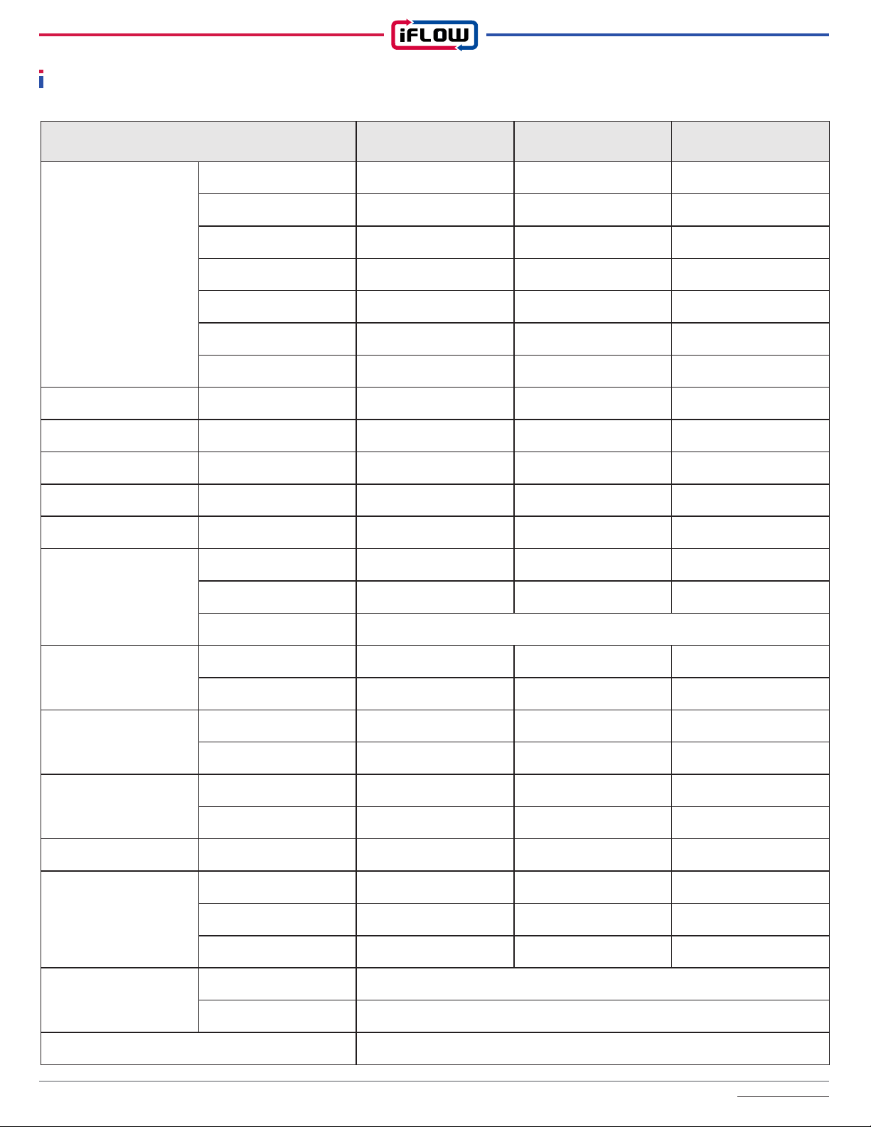
Description iFLH-140000 iFLH-160000 iFLH-180000
Heating
Capacity
@
Entering
Water
Temperature
120℉ 27,834 BTUH 34,211 BTUH 42,376 BTUH
130℉ 33,478 BTUH 41,357 BTUH 50,966 BTUH
140℉ 37,729 BTUH 48,379 BTUH 59,632 BTUH
150℉ 44,998 BTUH 55,485 BTUH 68,334 BTUH
160℉ 50,869 BTUH 62,632 BTUH 77,065 BTUH
170℉ 56,941 BTUH 69,769 BTUH 85,648 BTUH
180℉ 62,786 BTUH 76,982 BTUH 94,633 BTUH
Flow Rating LPM / GPM 11.4 / 3 11 / 2.9 10.6 / 2.8
Return Air Temp. ℃ / ℉ 22 / 72 22 / 72 22 / 72
E. S. P. inWC 0.6 / 1.2 0.6 / 1.6 0.6 / 1.6
Airflow SCFM 941 / 824 1222 / 1009 1423 / 1093
Cooling Capacity Ton 1 - 2 1.5 - 3 2 - 4
Cabinet Size
(W x D x H)
in 14 x 18 3/4 x 27 1/8 16 x 20 3/4 x 27 1/8 18 x 25 3/4 x 29 1/8
mm 356 x 476 x 689 406 x 527 x 689 457 x 654 x 740
Material Cold Roll Steel Sheet Metal / Powder Coated
Weight
kg 28.6 32 42
lb 63 71 92.5
Supply Air Opening
(W x D)
in 13 x 14 14 x 16 16 x 20
mm 330 x 356 356 x 406 406 x 508
Return Air Opening
(H x D)
in 12 x 16 13 x 18 14 x 23
mm 406 x 304 457 x 330 584 x 355
Electrical ACV/Hz/Ph AC 120V 60Hz 1Ph AC 120V 60Hz 1Ph AC 120V 60Hz 1Ph
Motor
HP 1 / 2 1 / 2 3 / 4
Type ECM Eon ECM Eon ECM Eon
W431 / 393 519 / 516 592
Piping Connection
Supply 3/4" Male NPT Thread / 1/2" Soldering Connection
Return 3/4" Male NPT Thread / 1/2" Soldering Connection
Hydronic Heating Coil Aluminum Ultra Efficiency Fins, Copper Tubing
Specification
iFLOW HVAC INC. www.iflowhvac.com
8
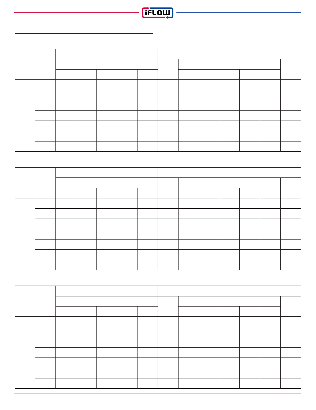
Water Heating Capacity (BTUH) / Water Pressure Drop (Feet)
iFLH-140000
H.Ex.
Rows
Entering
Water
Temp.
3 GPM 4 GPM
CFM
W.P.D
CFM
W.P.D
400 600 700 800 950 400 600 700 800 950
4
120℉ 17,365 21,756 23,654 25,347 27,834 2.9 18,425 23,097 25,653 27,246 29,906 4.3
130℉ 20,756 26,235 28,105 30,632 33,478 2.9 21,365 27,743 30,014 32,954 36,183 4.3
140℉ 24,142 30,754 33,521 36,065 37,729 2.8 24,845 32,469 35,478 38,549 42,376 4.2
150℉ 27,587 35,329 38,013 41,365 44,998 2.8 28,326 37,254 40,024 44,287 48,598 4.2
160℉ 30,965 39,865 43,247 46,759 50,869 2.8 31,824 41,987 45,726 49,976 54,843 4.1
170℉ 34,329 44,432 48,628 52,125 56,941 2.7 35,327 46,743 51,214 55,643 61,176 4.1
180℉ 37,734 49,032 54,573 57,683 62,786 2.7 39,836 51,458 56,429 61,398 67,497 4.0
iFLH-160000
H.Ex.
Rows
Entering
Water
Temp.
3 GPM 4 GPM
CFM
W.P.D
CFM
W.P.D
600 800 900 1000 1250 600 800 900 1000 1250
4
120℉ 24,625 27,865 29,865 31,087 34,211 3.7 28,268 30,042 31,986 34,109 38,287 5.7
130℉ 28,218 33,572 35,724 37,429 41,357 3.7 33,625 36,256 38,524 41,162 46,456 5.7
140℉ 32,865 39,218 41,625 43,843 48,379 3.7 38,245 42,367 45,412 48,235 53,971 5.5
150℉ 37,536 45,075 47,536 50,327 55,485 3.6 42,765 48,559 52,369 55,149 61,864 5.5
160℉ 42,125 50,732 53,425 56,798 62,632 3.6 47,325 54,632 58,489 62,268 69,832 5.4
170℉ 46,852 56,579 59,425 63,266 69,769 3.5 51,869 60,861 64,542 69,345 77,846 5.4
180℉ 51,425 62,329 65,325 69,747 76,982 3.5 56,465 67,054 72,369 76,486 85,742 5.3
iFLH-180000
H.Ex.
Rows
Entering
Water
Temp.
3 GPM 4 GPM
CFM
W.P.D
CFM
W.P.D
600 800 1000 1200 1450 600 800 1000 1200 1450
4
120℉ 28,963 34,245 35,648 38,946 42,376 5.6 30,125 36,203 38,224 42,376 46,638 6.9
130℉ 33,412 39,632 42,820 46,981 50,966 5.5 34,845 41,952 45,996 50,996 56,173 6.8
140℉ 37,954 45,126 50,157 54,844 59,632 5.5 39,652 47,623 53,756 59,465 65,789 6.7
150℉ 42,503 50,520 57,489 62,529 68,334 5.4 44,321 53,304 61,533 68,255 75,223 6.7
160℉ 47,127 55,963 64,732 70,931 77,065 5.3 49,032 59,123 69,325 76,905 84,896 6.6
170℉ 51,608 61,412 72,078 78,842 85,648 5.3 53,741 64,745 77,199 85,627 94,441 6.5
180℉ 56,129 66,846 79,354 87,055 94,633 5.2 58,429 70,487 84,923 94,336 104,056 6.4

iFLOW HVAC INC. www.iflowhvac.com
9
4. Suitable applications: Choosing the right heat source
The iFLOW air handler can be installed with various types of
heat sources and heating systems. The following are its primary
applications:
1. Air handler with tankless water heater
2. Air handler with conventional thank-type water heater
3. Air handler with heating boiler
4. Air handler with combi boiler
5. Air handler with heat pump + tankless water heater
6. Air handler with heat pump + tank-type water heater
7. Air handler with heat pump + boiler
8. Air handler with heat pump + combi boiler
Refer to the installation manual for diagrams of each type of installati-
on.
Hybrid Heating System
Definition:
A hybrid heating system is a dual-energy system using gas OR
electricity. The most common hybrid systems use a combination of
a furnace and heat pump to heat and cool a home. They can be a
fuel-saving alternative to traditional heating systems using only a
gas furnace. Hybrid systems use outdoor conditions to automatically
adjust to the most efficient method of heating, gas OR electricity.
Heat pump systems operate on electricity and are significantly more
energy efficient when compared to gas-operated furnaces. The heat
pump is effective alone at low temperatures close to 20 degrees
Fahrenheit. At that point, a gas furnace will kick in and help heat the
home.
You can save money with a heat pump. Heat pumps are an excellent
source of energy-efficient heat for your home, with the added benefit
of cooling your home in the summer months. With significant savings
over electric heat, heat pumps can reduce your energy bill without
changing the comfort level in your home.
Defrost cycle:
When the ambient temperature outside gets very cold (close to 0°C
or below) the moisture in the air freezes on the outdoor unit's heat
exchanger as the fan blows the air across it. A heat pump has a cycle
called a “defrost cycle,” which removes the frost from the outdoor coil.
A heat pump unit will defrost regularly when frost conditions occur.
The defrost cycle should be long enough to melt the ice, and short
enough to be energy-efficient. When a heat pump goes into defrost
mode, the heat pump shifts temporarily into the cooling mode to
reverse the flow of refrigerant through the coils. The reversing valve
activates and runs the refrigerant backward. Instead of extracting
heat from the outdoor air and putting it into the house, it extracts heat
from the house and sends it into the cold outdoor air.
iFLOW Hybrid heating System:
Definition:
The iFLOW Hybrid Heating System Control uses a dual-energy
system that uses gas AND electricity at the same time. This heating
system combines an iFLOW Hydronic Air Handler, using any water
heat source and a heat pump. It has the capability of running both at
the same time. The air heated as it passes across the hydronic coil
and the heat pump evaporator coil. The evaporator coils sit on top of
the iFLOW hydronic air handler.
Benefit:
The main benefit of the iFLOW Hybrid Heating System is its ability to
provide variable capacity heat, which is sufficient to provide the total
heat loss of a house regardless of the heat pump capacity. Therefore,
the defrost cycle will be long enough to melt the ice, and short
enough to be energy-efficient.
SMART MODE / SMART TEMPERATURE CONTROL MODE
In the General Parameters Setting Mode, the SMART MODE/SMART
TEMPERATURE CONTROL MODE can be selected to provide the
functions of the Smart Temperature Control without a thermostat.
When the SMART MODE/SMART TEMPERATURE CONTROL is
selected, the return air temperature sensor in the air handler will
sense an average air temperature from the space NOT the room air
temperature where the thermostat is located. This will provide better
control and comfort.
When the SMART MODE/SMART TEMPERATURE CONTROL is
selected the blower is always active while using this function. The
blower will run at the continuous blower speed setting selected.
*The DH Evap Defrost Sensor must be installed on
the suction pipe to operate for H/P.
DH Evap Defrost Sensor
A / C Evap T. Sensor

iFLOW HVAC INC. www.iflowhvac.com
Model Unit Width Depth Height a b c d
14" Cabinet
in 14 18 3/4 27 1/8 13 14 16 12
mm 355.6 476.3 689 330.2 355.6 406.4 304.8
16" Cabinet
in 16 20 3/4 27 1/8 14 16 18 13
mm 406.4 527.1 689 355.6 406.4 457.2 330.2
18" Cabinet
in 18 25 3/4 29 1/8 16 20 23 14
mm 457.2 654.1 739.8 406.4 508 584.2 355.6
10
AIR CONDITIONING AND HEAT PUMPS USED WITH ZONING
SYSTEMS
It is recommended that when zoning, air conditioning and heat pump
units used (with iFLOW air handler models iFLH-16000D, iFLH-
18000D and iFLH-18000Q with zoning) shall be variable speed
inverter type models. These units can ramp up or down in small
increments depending on the load.
Refer to Cooling Parameter Mode to set the blower speed
requirements for each zone and the minimum and maximum blower
speeds for cooling mode.
EXAMPLE ONLY
1) Location requirements and clearances:
• The installer shall comply with all local, state/provincial and national
code requirements that apply to the installation of this equipment.
• The air handler must be installed in such a way that electrical
components are protected from water during operation and service.
• If installed in an unconditioned space, sealant should be applied
around where the electrical wires, refrigerant tubing, and condensate
lines enter the cabinet. This appliance shall not be installed in a non-
conditioned space where the potential may exist for the appliance,
water lines and/or drain lines to freeze.
• If installed with air conditioning in a suspended application, ensure a
drain pan with a proper slope is installed.
Recommended Clearances:
Be sure to provide a minimum of 24” clearance to the front panel
of the iFLOW air handler. 0” clearance is allowed for all other sides
of the cabinet and for the first 36” of ductwork. Ensure adequate
clearance is left for the installation of ductwork, plumbing, and
electrical connections.
LEFT SIDE
0 inch
RIGHT SIDE
0 inch
BACK
0 inch
PLENUM
0 inch
BOTTOM
0 inch
FRONT
SERVICING
2) Dimensions
Installation
iFLOW HVAC INC. www.iflowhvac.com
11
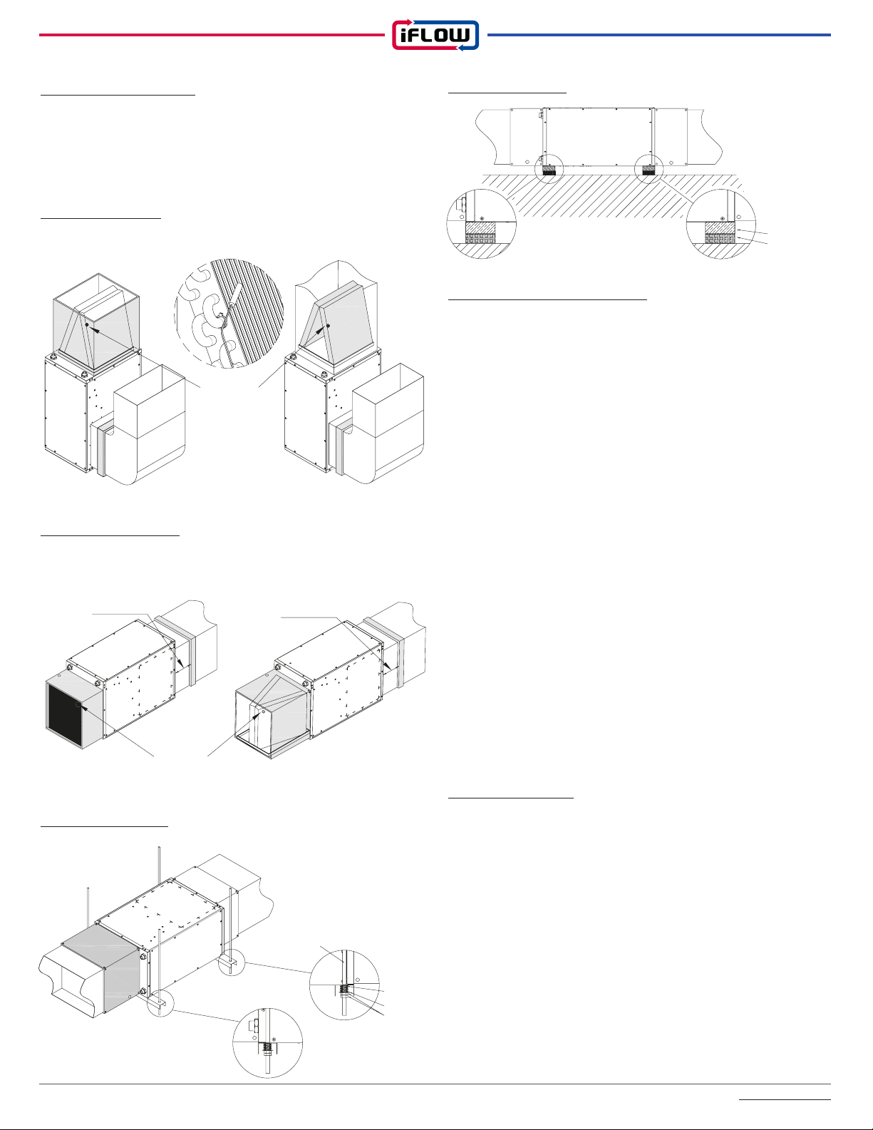
3) Installation examples:
The iFLOW air handler is multi-positional and therefore can be
mounted in any position. If installed with air conditioning, proper
positioning of the evaporator coil and drain line must be considered to
install correctly.
Vertical Installation
Horizontal Installation
The evaporator coil must be installed on the supply side of the air
handler.
Hanging Installation
Ceiling Installation
4) Water Heater / Boiler Piping:
When installing the iFLOW air handler with a heating boiler or combi-
boiler in a closed loop system, refer to the boiler manufacturer’s
instructions for proper installation with an air handler. Depending on
the boiler selected and system design, it may be required to use a
primary/secondary piping arrangement to de-couple the flow through
the boiler from the flow through the air handler.
Air-removal device:
Provisions shall be made for the removal of air in the heat-distribution
piping system. The air-removal device shall be located in the area
of the heat-distribution piping system where the air is likely to
accumulate (often the highest point in the system).
Required Components:
Expansion tank, isolation valves, air eliminator, dirt collector/filter/
strainer (if other heating loads are being heated by the same boiler),
make-up water and low loss header (optional).
Sensor Installation
A/C Evaporator Temperature Sensor: Air outlet on the Evaporator
coil (See Installation Illustration: Page 12)
Zone Air Temperature Sensor:
Zone supply side: Air outlet of the damper
Zone return side: Air inlet of the damper (if there is a dedicated return
duct with the damper)
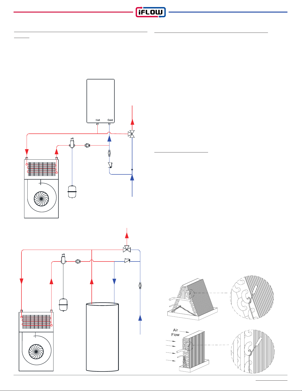
5) Domestic Piping:
Notes: When installing the iFLOW air handler with a water heater,
refer to the manufacturer’s guidelines on coupling the water heater
with an air handler. Use components and piping that are allowable
with potable use. Lead-free solder must be used on all joints.
When both top and side connections are present on the water heater,
the side connections should be used for the space-heating loop.
The heating loop connections should be positioned horizontally in a
vertical section of the domestic water line for both the inlet and outlet.
Refer to the piping diagram for details. Minimize the distance and
piping between the water heater and the iFLOW air handler.
If the main water line has an installed check valve, a potable
expansion tank must be installed to provide room for the expansion
of water.
AHU with
Case Coil or A Coil
Evaporator
Temperature
Sensor position
Filter Rack Filter Rack
Minimum 6inch
Filter Rack Filter Rack
Minimum 6inch
Evaporator
Temperature
Sensor position
AHU with
Slab Coil
AHU with
Case Coil or A Coil
Support
Anti-Vibration Pad
The Threaded Rod
Spring
Flat washer
Nut
iFLOW HVAC INC. www.iflowhvac.com
12
6) Installing the iFLOW air handler with a tankless/tank water
heater:
Check with the tankless water heater manufacturer prior to installation
to ensure it can be used for combo space heating applications. Make
sure to check that the valves, including but not limited to the purge
and isolation valves are properly installed. If connecting to a tankless
water heater, the circulating pump needs to be sized correctly.
7) Electrical requirements and making connections:
This unit requires single phase AC 120V power to operate and must
be hardwired. To connect, follow these directions:
1. To avoid electrical shock, turn off electrical power at the breaker
dedicated to the air handler. Ensure the power remains off while any
wiring connections are being made.
2. Remove the iFLOW front access panel.
3. Route the field supplied line voltage wiring to the iFLOW air
handler.
4. Using CSA & UL listed wire nuts, connect the field supplied wires
to the air handler (black to black and white to white).
5. Connect ground wire to GND terminal.
6. Repeat the process for the circulating pump (connect to terminal
block).
7. Route low voltage thermostat wire to the unit; connect to
thermostat terminal on control board.
8. Re-secure the front access panel.
8) Temperature sensors:
The iFLOW air handlers come equipped with 5 wire sensors that plug
into connectors on the control board for easy servicing.
1. Supply water sensor: mounted on the supply end of the water
heating coil.
2. Return water sensor: mounted on the return end of the water
heating coil.
3. Supply air sensor: mounted above the water heating coil exchanger
to detect supply air temperature and freezing temperatures.
4. Outdoor temperature sensor: modulates air handler operation
based on outdoor temperature. Provides outdoor reset function.
5. Return air sensor: factory installed in return air path blower. If you
install a slab coil on the return air side, you must install the return air
sensor before(or upstream of) the slab coil.
6. A/C Evap sensor: mount on the A coil, or on the slab coil. It should
be installed on the surface of the cold air outlet on the evaporator or
the U-bend pipe. Refer to the figure below.
Air
Elliminator
Expansion
Tank
Circulator
with
Check Valve
Flow
Switch
Check
Valve
Tank
Water Heater
D H W
An�Scald
Valve
Cold
Water
An�Scald
Valve
Tankless
Water
Heater
Circulator
Expansion
Tank
Flow
Switch
Check
Valve
D H W
Cold
Water
Air
Elliminator

iFLOW HVAC INC. www.iflowhvac.com
10) Zone Damper
Zone Temperature Sensor Installation and Control Wiring
11) Wi-Fi Module connect to iFLOW control boards
WiFi Module sold separately.
Refer to set up manual, how to use with smartphone
13
9) Installing the iFLOW air handler with a Navien tankless
water heater:
Use the optional communication cable between the iFLOW AHU
and the Navien tankless water heater. Connect the thermostat to the
iFLOW AHU at the thermostat connector. Connect the communication
cable from the iFLOW AHU to the cascade communication port on
the Navien Water Heater Panel. The parameter P28 of the NAVIEN
TL WH should be set to ON ( Refer to Navien Tankless Water
Heater Installation Manual)
No Description Part # Model Remark
1iFLOW Communication Cable 30NWCC05 Length: 5m
2iFLOW Communication Cable 30NWCC10 Length: 10m
No Description Part # Model Remark
1 6" Damper 2000D06A
AC24V 5W
2 7" Damper 2000D07A
3 8" Damper 2000D08A
Supply Air Temp. Sensor
Hole " Diameter
Return Air Temp. Sensor
Hole " Diameter
No Description Part # Model Remark
1WiFi Module 30WFA00A Option
iFLOW HVAC INC. www.iflowhvac.com
14
1) Procedure:
Do not start the boiler or water heater until ALL air has been purged
from the water lines and air handler pump.
1. Fill the boiler loop or water heater with water. Do not start it.
2. Purge all air from the heating boiler or domestic hot water system
(Hold the UP & ENTER button for 10 seconds and then the circulator
will alternate power ON and OFF for about 10 minutes to purge air).
3. Purge all air from the space heating loop by closing the isolation
valve on the return leg of the loop and open the drain to purge the air.
Open the return leg isolation valve and then close the drain valve.
4. If a bleed screw is not present, it is recommended to run the pump
on speed #3 for 1 minute. If air is still present, switch from speed #1
to #3 every 10 seconds for a minute.
5. Start the boiler or water heater according to the manufacturer’s
instructions. Set the design water temperature and wait for the
system to satisfy and shut off.
6. Turn on the power to the iFLOW air handler and set the room
thermostat to ‘heat’ to energize the fan and pump. If noise is still
present after one minute, repeat step #3 to purge air.
7. Check supply and return pipes for temperature differences to
make sure there is flow. There should be a noticeable difference in
temperature. Use caution when supply water temperature is above
120˚ F.
2) Flushing the heat exchanger:
Flushing the hot water coil prior to startup is required to remove any
residual material from the installation or manufacturing processes as
well as to remove any air from the system. Take precautions while
flushing the air handler to prevent the multi-function control board and
other electrical components from getting wet.
The iFLOW air handler requires an external circulating pump to be
installed and should be installed with an external purge valve.
Flushing is a 3-step process:
1) Use a bucket or hose to dispose of water during the flushing
process. First, flush the return line by closing the inlet valve (supply)
and opening the outlet valve (return). Open the purge valve. Close
the purge valve once flushing is complete.
2) Second, flush the supply line and coil by closing the outlet valve
(return) and opening the inlet valve (supply). Open the purge valve.
Close the purge valve once flushing is complete.
3) Third, apply power to the air handler. Open inlet and outlet valves.
Engage the pump and open the purge valve. Verify proper flow
direction - inlet valve should become warm before the outlet. Close
the purge valve once flushing is complete. Operate the pump for 5
minutes immediately after flushing the system to purge remaining air
from the pump bearing chamber.
3) Sequence of operation:
Cooling: When the thermostat calls for cooling, the circuit between
R and G is completed. The normally open contacts close and the air
handler blower motor operates. The circuit between R and Y is also
completed; this closes the contact on the outdoor condenser unit.
The air handler fan turns off 45 seconds after the call for cooling is
completed.
Heating: When the thermostat calls for heat, the circuit between R
and W is completed, activating the hot water circulating pump. A dry
switching relay labeled “T T” can be used to activate a boiler or combi
boiler. After the circuit between R and W is completed, a time delay
follows before the circuit between R and G is completed, which will
then activate the air handler blower motor.
Freeze protection: If the temperature of the water in the hot water
coil drops below 40°F/4°C, the circuit between R and W is completed.
This will activate the circulating pump until the water temperature
reaches 70°F.
Pump timer/ exercise function: The iFLOW control is equipped to
turn on the circulating pump to cycle the total volume of potable water
in the system if the pump has not been turned on within the past
24 hours. This function is skipped while the A/C condensing unit is
operating.
How to Access and Configure the iFLOW Intelligent
Controller
The controller has 6 modes:
The controller has 4 buttons used to navigate those modes:
MODE: Press the ‘MODE’ button to scroll between the different
modes, numbered 1-6 (see above).
ENT: Press the ‘ENT’ (enter) button to confirm the mode you wish to
enter. Press ‘enter’ to also confirm any changes or commands that
you selected using the ‘up’ and ‘down’ buttons (see below) while in
each mode.
UP & DN: Once you are in a ‘mode’, press the ‘UP’ and ‘DN’ (down)
buttons to scroll all menu lists of the various information.
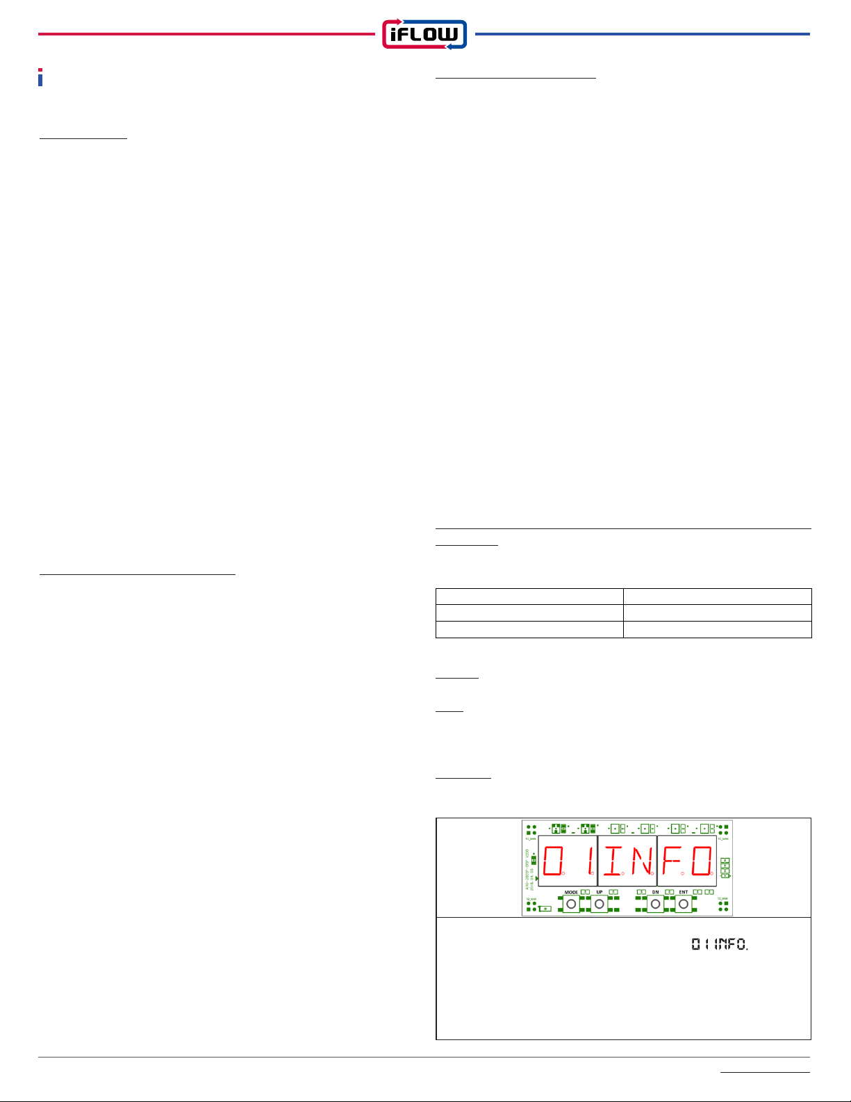
Information Mode
How to access Information display:
Push the ‘MODE’ button until the screen reads
Press ‘ENT’ (enter) to confirm you wish to enter the information
mode. Use the ‘UP’ and ‘DN’ (down) buttons to scroll through the
menu of information available. The information available varies
depending on the model of air handler. The 4 characters on the right
indicate the value.
START-UP
1. Information
2. Error Codes
3. General Parameters
4. Heating Parameters
5. Cooling Parameters
6. Test Mode
iFLOW HVAC INC. www.iflowhvac.com
15
Display Description Explanation
Boiler TT State
Indicates whether the air
handler is currently sending a
dry contact call for heat to the
connected boiler
(ON = calling boiler on;
OFF= not calling boiler on)
A/C Y1 Relay State
Indicates whether the air handler
is sending an AC 24V cooling
call to the A/C condensing unit
A/C Y2 Relay State
Indicates whether the air handler
is sending an AC 24V cooling
call to the A/C condensing unit
H/P W1 Relay State
Indicates whether the air handler
is sending an AC 24V heating
call to the H/P condensing unit
H/P W2 Relay State
Indicates whether the air handler
is sending an AC 24V heating
call to the H/P condensing unit
Dehumidifier Relay
State
Indicates whether the humidifier
is in the ‘on’ or ‘off’ state (is relay
supplying 24V or not?)
Humidifier Relay
State
Indicates whether the external
humidifier, which is wired to the
control board, is in the ‘on’ or ‘off’
state (is relay supplying 24V or
not?)
Water Adjustment
Valve
Reserved for future cool
functionality
Communication
Connection Status
RS485 Communication Cable
State with Navien Tankless
Water Heater (ON/OFF)
Time
(24 hr HH:MM)
Current time display
(24 hour clock = HH:MM)
Zone 1 Supply
Damper State
Zone 1 Supply Damper Opening
Ratio (0%= Fully Closed ~
100%=Fully Opened)
Zone 1 Supply
Temperature
Zone 1 Supply Air Temperature,
in °F
Zone 1 Return
Damper State
Zone 1 Return Damper Opening
Ratio (0%= Fully Closed ~
100%=Fully Opened)
Zone 1 Return
Temperature
Zone 1 Return Air Temperature,
in °F
Zone 2 Supply
Damper State
Zone 2 Supply Damper Opening
Ratio (0%= Fully Closed ~
100%=Fully Opened)
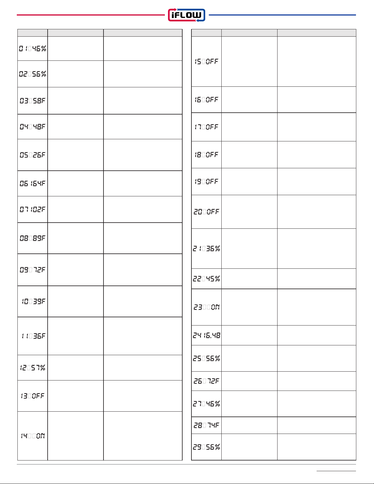
Display Description Explanation
Blower Motor Speed
Indicates present operation as
a percentage of the total fan
motor capacity
Pump Speed
Indicates present pump
operation as a percentage of
the total capacity of the pump
Water Temperature ∆t
(Delta T)
Indicates the difference between
the supply and return water
temperature in °F
Air Temperature ∆t
(Delta T)
Indicates the difference between
the supply and return air
temperature in °F
Outdoor
Temperature
Displays the outdoor air
temperature in °F. (If outdoor
sensor is not installed, 999 will
be displayed)
Supply Water
Temperature
Displays the temperature of the
water entering the hydronic coil
heat exchanger, in °F
Return Water
Temperature
Displays the temperature of the
water exiting the hydronic coil
heat exchanger, in °F
Supply Air
Temperature
Displays the temperature of the
air exiting the air handler into
the plenum, in °F
Return Air
Temperature
Displays the temperature of the
air entering the air handler from
the return duct, in °F
A/C Evaporator
Temperature
Displays the current temperature
of the air sensor attached
downstream of, but near the
evaporator coil in °F
Dehumidifier
Evaporator
Temperature
Displays the current temperature
of the sensor located in the
dehumidifier evaporator, in °F
(If d.h. sensor is not installed,
999 will be displayed)
Humidity Value
Measured value of the current
humidity in the return section of
the unit
Flow Switch On/Off
State
Indicates whether the external
flow switch, which is wired to the
control board, is activated or not
(ON = flow; OFF= no flow)
Pump Relay State
Indicates whether the external
pump (field supplied) should be
in operation (is power supplied
by relay to pump?)
(ON = should be operating;
OFF= should not be operating)

iFLOW HVAC INC. www.iflowhvac.com
16
Display Description Explanation
EXAMPLE OF LAST 10 ERROR CODES
Display Description Explanation
EXAMPLE OF LAST 10 ERROR CODES
Item Display Range Default
Temperature Unit of
Measure Set 0=℃, 1=℉ 1
Select the temperature units of measure you wish to display:
Celsius or Fahrenheit
Humidifier 35 – 65% 45%
Select the rate of humidity, below which, the humidifier will operate.
General Parameter Settings Mode
Push the mode button until the screen reads
Press ‘ENT’ (enter) to confirm you wish to enter the General
Parameters Mode. Use the ‘UP’ and ‘DN’ (down) buttons to scroll
through the menu of General Parameters, numbered 01-20 and
press enter to select. The 1-3 characters on the right indicate the
value. Use the up and down buttons to change the range of the
value and press ‘ENT’ (enter) to confirm and ‘MODE’ to exit.
How to access Error codes:
Display Description Explanation
Zone 2 Supply
Temperature
Zone 2 Supply Air Temperature,
in °F
Zone 2 Return
Damper State
Zone 2 Return Damper Opening
Ratio (0%= Fully Closed ~
100%=Fully Opened)
Zone 2 Return
Temperature
Zone 2 Return Air Temperature,
in °F
Zone 3 Supply
Damper State
Zone 3 Supply Damper Opening
Ratio (0%= Fully Closed ~
100%=Fully Opened)
Zone 3 Supply
Temperature
Zone 3 Supply Air Temperature,
in °F
Zone 3 Return
Damper State
Zone 3 Return Damper Opening
Ratio (0%= Fully Closed ~
100%=Fully Opened)
Zone 3 Return
Temperature
Zone 3 Return Air Temperature,
in °F
Zone 4 Supply
Damper State
Zone 4 Supply Damper Opening
Ratio (0%= Fully Closed ~
100%=Fully Opened)
Zone 4 Supply
Temperature
Zone 4 Supply Air Temperature,
in °F
Zone 4 Return
Damper State
Zone 4 Return Damper Opening
Ratio (0%= Fully Closed ~
100%=Fully Opened)
Zone 4 Return
Temperature
Zone 4 Return Air Temperature,
in °F
Error Codes
Push the mode button until the screen reads
Press ‘ENT’ (enter) to confirm you wish to enter the Error code
mode. Use the ‘UP’ and ‘DN’ (down) to scroll through the last 10
errors which will be numbered 01 to 10, with 01 being the most
recent. The 3 numbers on the right will indicate which error code is
present. If more than 10 errors occur, the oldest error will be deleted
from the memory.
How to access Error codes:

iFLOW HVAC INC. www.iflowhvac.com
17
Item Display Range Default
‘Maximum Heating ON’
Coldest Outdoor
temperature
0 – 32 °F 5
Enter the coldest outdoor temperature, below which, you expect the
heating to run a maximum.
‘Heating OFF’ Warm
Outdoor temperature 59 – 80 °F 70
Enter the outdoor temperature, above which, the heating will not
operate.
Building’s Total Heat Loss
15 – 60/75/95K
BTU (de-
pending on
model)
Enter the home’s estimated heat loss. Identifies the target maximum
BTUH output required for the AHU.
Number of Supply Zones
Range: 1 ~ 4
SZ=1, DZ=2,
QZ= 3 or 4
SZ=1,
DZ=2,
QZ=4
Sets the number of supply zones for the controller to expect.
Reserved Future Cool
Function
Zone Air Mix Function 0=OFF, 1= ON 0
The Zone Air Mix Function is used to measure the temperature of
each zone when heating or cooling is requested. Any stratified air
is mixed before operating the heat / AC source (i.e.: in summer,
circulate hot air from upper floors with cold air in basement).
Zone Air Mix
Temperature Differential 0 – 10 °F 3
When the Zone Air Mix Function (above) is selected and once the
stratified zone mixing has been completed, the iFLOW AHU will
operate the heat / A/C source only if the mixed temperature of any
zone differs by more than the differential (set using this function)
from the zone setpoint temperature.
Damper Opening Duration 1 – 60 Second 7
Enter the time (in seconds) that it takes for the zone dampers to
initialize and fully open. iFLOW will ensure the AHU blower does not
come on until the dampers are fully open and that power supplied to
the dampers does not exceed that time. The iFLOW dampers have a
7 second ‘closed to open’ duration so that is default. Other damper
manufacturers are typically slower so adjust 7 to a higher number.
Item Display Range Default
‘Heating OFF’ Indoor
Temperature Limit 74 – 90 °F 85°F
Select the indoor temperature, above which, the heating will
automatically stop.
‘A/C Cooling OFF’ Indoor
Temperature Limit 60 – 70 °F 65°F
Select the indoor temperature, below which, the cooling will
automatically stop.
Pump Exercise Frequency
Set Up (Anti-Stagnation) 0 – 24 Hours 24
CSA B214 requires pump circulation once every 24 hours (default).
Some jurisdictions may require a shorter time interval based upon
local codes (ex.: if the pump must cycle once every 8 hours, set at
060008).
Pump Exercise
Duration Set Up 30 – 600 sec 30
Determines the duration the pump runs for during the Exercise cycle
(above). The circulation time should be adjusted according to the
pipe length between the heat source and the iFLOW AHU to ensure
full circulation.
Pump Duty ON 0.0 – 5.0 sec 1.0
When the heat source selected is a tankless water heater (except
Navien), use this setting to circulate but without triggering a burner
‘on’ condition. To do that, maintain the flow rate low enough and/or
the duration short enough so the burner does not ignite. With the
Pump Duty ON (this function) and Pump Duty OFF function (below),
set up a pulse sequence to achieve this objective. The pump will
turn on for a short period of time (Pump Duty ON) and then turn off
for a period of time. (Pump Duty OFF).
The default length of time the pump operates is 1 second, however
depending on the tankless water heater, this duration may need to
be adjusted.
Pump Duty OFF 0.0 – 5.0 sec 3.0
When the heat source selected is a tankless water heater (except
Navien), during the “Pump Duty OFF” function, the pump will turn off
for a short period of time. Depending on the tankless water heater,
this duration may need to be adjusted, however the duration of the
“Pump Duty OFF” must always be longer than “Pump Duty ON.”
If the burner does light, it will not harm the equipment at all; it just
means the heating and cooling will be running simultaneously for the
Pump Exercise Duration (30 seconds once every 24 hours if using
default settings).
Heat Boost Delay 0 – 60 min 30
Use this function to quickly increase the heat delivery. If the room
temperature does not rise more than 2˚F within the set time, the
Heat Boost function will engage and run at maximum until the room
thermostat is satisfied. Set the parameter above for the duration the
heating will operate at normal before boosting.
Continuous Circulation
(‘G’ Call) Blower Speed 5 – 50 % 10
Set the blower speed when running on ‘G’ / Fan On / Continuous
Circulation
45/55/65
(depending
on
model)

iFLOW HVAC INC. www.iflowhvac.com
18
Item Display Range Default
Minimum Pump Speed 35 ~ 100 % 45 %
Used for advanced adjustment & troubleshooting only. Sets the
pump speed when a W1 heating call is received.
Minimum Blower Motor
Speed Control 10 ~ 100 % 20 %
Used for advanced adjustment & troubleshooting only. Sets the
blower motor speed when a W1 heating call is received.
Reserved
Future
Cool
Function
Maximum Pump Speed 35 ~ 100 % 80 %
Used for advanced adjustment & troubleshooting only. Sets the
pump speed when a W2 heating call is received.
Maximum Blower Motor
Speed Control 10 ~ 100 % 60 %
Used for advanced adjustment & troubleshooting only. Sets the
blower motor speed when a W2 heating call is received.
Blower ON Delay Time 10 ~ 120
Seconds
30
Seconds
Used for advanced adjustment & troubleshooting only. On a call for
heat, iFLOW delays blower motor operation until the hydronic coil
receives heat from the heat source (avoids blowing any cold air).
Blower OFF Delay Time 0 ~ 180
Seconds
90
Seconds
Used for advanced adjustment & troubleshooting only. Delays
blower motor shut off once a call for heat is completed to maximize
efficiency. iFLOW continues to circulate the blower to deliver any
residual coil heat to the home. Use this function in combination with
Setting #8 ‘Post Purge Function’ below. Set #8 to “1”
Post Purge Function 0: OFF 1: ON 1
Used for advanced adjustment & troubleshooting only. Sets
the pump to continue to run after a heat demand to maximize
efficiency by extracting all residual heat from the heat source.
iFLOW continues to circulate the pump to deliver any residual heat
to the hydronic coil, instead of the heat source post-purging its
residual waste heat through the exhaust vent. Use this function in
combination with Setting #7 ‘Blower Off Delay Time’ above.
DHW Priority 0 = ON, 1=OFF 1
Used for advanced adjustment & troubleshooting only. When a flow
switch on the cold water supply is installed and wired to the iFLOW
AHU, iFLOW offers DHW Priority. Set whether or not the air handler
should shut down during periods where there is a demand for
domestic hot water.
For cool
future
function
Heating Parameter Mode
How to access Heating Parameter:
Push the mode button until the screen reads
Press ‘ENT’ (enter) to confirm Heating Parameter Mode. Use the
‘UP’ and ‘DN’ (down) buttons to scroll through the menu of heating
parameters, numbered 01-16. The 1-3 characters on the right
indicate the value. Use the up and down buttons to change the
range of the value and press ‘ENT’ to confirm and ‘MODE’ to exit.
Item Display Range Default
Smart Mode 0= OFF, 1=ON 0
There are 2 way to deliver temperature to the home: 1) Thermostat
Mode and 2) Smart Mode. Thermostat mode relies on the room
thermostat to provide a signal for the air handler to come on and
turn off. Smart Mode by-passes the room thermostat and instead
circulates air continuously through the home and relies on the return
air temperature to indicate if more or less heating/cooling required.
The ECM blower is default set at 10% but can be set as low as 5%
to minimize energy consumption. See ‘General’ parameter #11
(Continuous Circulation (‘G’ Call) Blower Speed) to adjust. WiFi
mode must be set to ‘internet’. Also use this function when zoning
but do not have a thermostat for every zone (i.e.: in a retrofit, when
you cannot run new wire).
Wi-Fi Mode 0=Internet,
1=Paring 1
There are 2 ways to connect to, and communicate with the iFLOW
Air Handler using the iFLOW App: through the internet or by pairing.
Through the internet requires the contractor or homeowner to
connect the iFLOW Air Handler to the homeowner’s local home Wi-
Fi network. Pairing connects your smartphone to the air handler
without a local network (similar to pairing a phone to a car’s stereo).
In pairing mode, the phone must be in close proximity of the iFLOW
unit.
Emergency Mode
0=OFF,
1=Heat,
2=Cool
0
Use this setting to override the thermostat and run the heating or
cooling automatically in an emergency. Provides emergency heating
or cooling should there be a thermostat failure.
Schedule Mode 0=OFF, 1=ON 0
Use this mode to select whether you want to use the iFLOW
scheduling function.
Day
1:SUN 2:MON
3:TUE 4:WED
5:THU 6:FRI
7:SAT
SUN
Set current day of the week
Time HH:0~24,
MM:0~59
Current
Time
Set current time (24 hour clock)
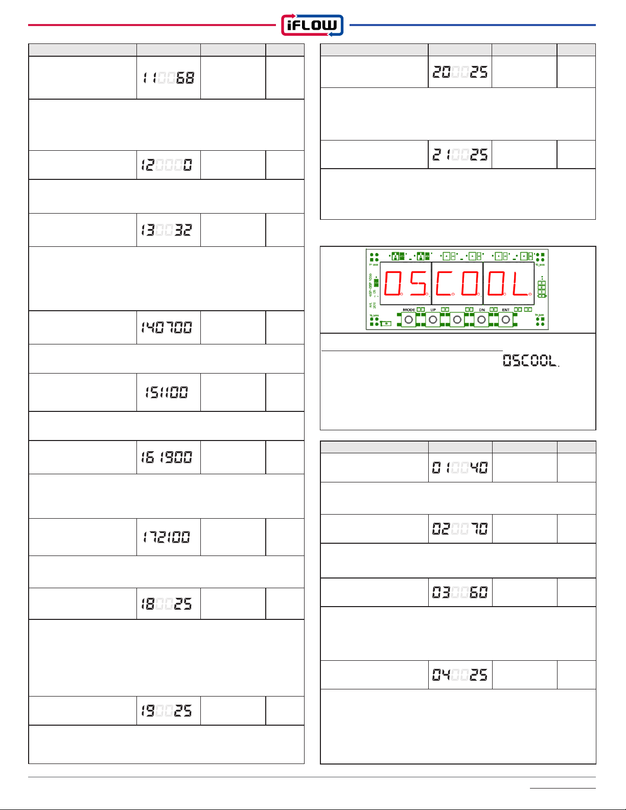
iFLOW HVAC INC. www.iflowhvac.com
19
Item Display Range Default
Coldest Indoor
‘Maximum Heating ON’
Temperature
60 ~ 80 °F 68˚F
Set a base temperature such that if the return air temperature
goes below that temperature (default is 68˚F), the unit will run at
maximum capacity. This temperature should be below any daytime
or nighttime ‘setback’.
Heat Source Type(s) 0, 1 0
0 : Hot Water Only (water heater, boiler or combi-boiler)
1: Hot Water + heat pump (Hybrid)
Outdoor Temperature for
‘H/P Heating OFF’
23 ~ 41˚F
(-5˚ ~ 5˚C) 32˚F
Set the lowest temperature at which you wish the heat pump
to operate (Balance Point Consideration: H/P COP and cost of
electricity at that temperature vs. gas efficiency and cost of gas).
Below that temperature, iFLOW will switch to the gas hot water
source.
‘Peak Rate Period 1 Start ’
- H/P Stop 00:00~24:00 07:00
Electricity Off-peak On time Set
‘Peak Rate Period 1
Finish’
- H/P Start
00:00~24:00 11:00
Use this function to start operating the heat pump again at end of
the ‘peak’ period 1 (started above).
‘Peak Rate Period 2 Start ’
- H/P Stop 00:00~24:00 19:00
If the electric utility has peak rates, use this function to stop operating
the heat pump at the beginning of the ‘peak’ period 2. (Refer to your
electric utility’s Time-of-Use Pricing and Schedule)
‘Peak Rate Period 2
Finish’
- H/P Start
00:00~24:00 21:00
Use this function to start operating the heat pump again at end of
the ‘peak’ period 2 (started above).
Zone 1 Blower Speed
(Heating Mode) 0 ~ 100 % 25%
Set the blower motor speed for zone 1 as a percentage of the
home’s total heat loss or CFM requirement. For example, if the
home’s total heat loss is 60MBH and Zone 1 accounts for 20MBH
(1/3) of that loss, the percentage would be 33%. If the home’s total
CFM requirement is 1200 CFM and Zone 1 accounts for 400 CFM
(1/3) of that loss, the percentage would be 33%.
Zone 2 Blower Speed
(Heating Mode) 0 ~100 % 25%
Set the blower motor speed for zone 2 as a percentage of the
home’s total heat loss or CFM requirement (see Zone 1 above for
details).
Item Display Range Default
Zone 3 Blower Speed
(Heating Mode) 0 ~ 100 % 25%
Set the blower motor speed for zone 3 as a percentage of the
home’s total heat loss or CFM requirement (see Zone 1 above for
details).
Zone 4 Blower Speed
(Heating Mode) 0 ~ 100 % 25%
Set the blower motor speed for zone 4 as a percentage of the
home’s total heat loss or CFM requirement (see Zone 1 above for
details).
Cooling Parameter Mode
Push the mode button until the screen reads
Press ‘ENT’ (enter) to confirm Heating Parameter Mode. Use the
‘UP’ and ‘DN’ (down) buttons to scroll through the menu of heating
parameters, numbered 01-16. The 1-3 characters on the right
indicate the value. Use the up and down buttons to change the
range of the value and press ‘ENT’ to confirm and ‘MODE’ to exit.
Item Display Range Default
Minimum Blower Motor
Speed Setting 10 ~ 50 % 40 %
Used for advanced adjustment & troubleshooting only. Sets the
blower motor speed when a Y1 cooling call is received.
Maximum Blower Motor
Speed Setting 10 ~80% 70%
Used for advanced adjustment & troubleshooting only. Sets the
blower motor speed when a Y2 cooling call is received.
Blower OFF Delay Time 0 ~ 300 sec 60 Sec
Used for advanced adjustment & troubleshooting only. Sets a delay
of the blower motor shutting off after a call for cooling is completed.
To maximize efficiency, iFLOW continues to circulate the blower to
deliver any residual coil cooling to the home.
Zone 1 Blower Motor
Speed (Cooling Mode) 0 ~ 100 % 25%
Set the blower motor speed for zone 1 as a percentage of the
home’s total cooling load or CFM requirement. For example, if the
home’s total cooling load is 30MBH and Zone 1 accounts for 10MBH
(1/3) of that loss, the percentage would be 33%. If the home’s total
CFM requirement is 1200 CFM and Zone 1 accounts for 400 CFM
(1/3) of that loss, the percentage would be 33%.
How to access Cooling Parameter:
iFLOW HVAC INC. www.iflowhvac.com
20
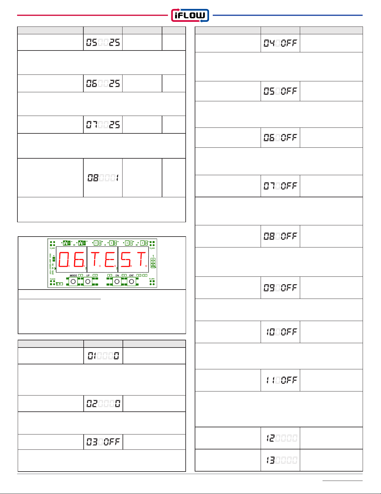
Test Mode
How to access Test codes:
Push the mode button until the screen reads 06TEST. Press
‘ENT’ (enter) to confirm the test mode. Use the ‘UP’ and ‘DN’ (down)
buttons to scroll through the menu of tests, numbered 01-20. Use the
up and down buttons to change the values. Press ‘MODE’ to exit.
Item Display Test Operation
Boiler T T Relay Test
Press enter while 04 is flashing. Display will show OFF. Use ‘UP’ or
‘DN’ button to turn on. Boiler TT Relay will start immediately. Press
enter to exit.
H / P Relay W1 Test
Press enter while 05 is flashing. Display will show OFF. Use ‘UP’
or ‘DN’ button to turn on. H/P Relay W1 Test will start immediately.
Press enter to exit.
H / P Relay W2 Test
Press enter while 06 is flashing. Display will show OFF. Use ‘UP’
or ‘DN’ button to turn on. H/P Relay W2 Test will start immediately.
Press enter to exit.
A / C Relay Y1 Test
Press enter while 07 is flashing. Display will show OFF. Use ‘UP’
or ‘DN’ button to turn on. A/C Relay Y1 Test will start immediately.
Press enter to exit.
A / C Relay Y2 Test
Press enter while 08 is flashing. Display will show OFF. Use ‘UP’
or ‘DN’ button to turn on. A/C Relay Y2 Test will start immediately.
Press enter to exit.
Dehumidifier Relay Test
Press enter while 09 is flashing. Display will show OFF. Use ‘UP’ or
‘DN’ button to turn on. Dehumidifier Relay Test will start immediately.
Press enter to exit.
Humidity Relay Test
Press enter while 10 is flashing. Display will show OFF. Use ‘UP’ or
‘DN’ button to turn on. Humidifier Relay Test will start immediately.
Press enter to exit.
Flow Switch Test
Press enter while 11 is flashing. Jumper terminals FS on the right
side of the control board. The display will flash ON if it is working
correctly. You can also open a hot water faucet; this should trip the
switch to ON.
Reserved Future cool function
Reserved Future cool function
Item Display Test Operation
Blow Motor Speed Control 0 ~ 100%
Press enter while 01 is flashing. Display will flash 0. Use ‘UP’ or
‘DN’ buttons to change blower speed value from 0-100%. Blower
will speed up and down as you increase or decrease the value,
respectively.
Pump Speed Control 0 ~ 100 %
Press enter while 02 is flashing. Display will flash 0. Use ‘UP’ or ‘DN’
buttons to change value from 0-100% pump speed. Pump will speed
up and down as you increase or decrease the value, respectively.
Pump Relay
Press enter while 03 is flashing. Display will show OFF. Use ‘UP’ or
‘DN’ button to turn on. Relay test will start immediately. Press enter
to exit.
Item Display Range Default
Zone 2 Blower Motor
Speed 0 ~ 100 % 25%
Set the blower motor speed for zone 2 as a percentage of the
home’s total cooling load or CFM requirement (see Zone 1 above for
details).
Zone 3 Blower Motor
Speed 0 ~ 100 % 25%
Set the blower motor speed for zone 3 as a percentage of the
home’s total cooling load or CFM requirement (see Zone 1 above for
details).
Zone 4 Blower Motor
Speed 0 ~ 100 % 25%
Set the blower motor speed for zone 4 as a percentage of the
home’s total cooling load or CFM requirement (see Zone 1 above for
details).
A/C Type Selection
(when Zoning)
0=single stage
A/C
1= inverter A/C
or HP
2=Inverter 2 A/
C or HP
1
0=Single stage A/C: all zone dampers will open. 1=inverter A/C:
1 zone will open at a time. 2=Inverter 2 A/C: multiple zones open
simultaneously
This manual suits for next models
8
Table of contents
Other iFlow Air Handler manuals

Popular Air Handler manuals by other brands

Mars
Mars Comfort-Aire Century VCD18 SA Series owner's manual

BLAUBERG
BLAUBERG VUT 270 V5B EC user manual

Trox Technik
Trox Technik FK2-EU Additional manual

Lennox
Lennox LNINVE052 Service manual

Trane Technologies
Trane Technologies THERMO KING UT-1290 installation manual

Armstrong Air
Armstrong Air BCE7S Series installation instructions


Mars
Mars Century Comfort-Aire HRG18 S1P Series Service manual

Midea
Midea 40MBAA installation instructions

ECR International
ECR International EMI DHMZ218DA Installation, operation and maintenance manual

Vents
Vents VUT 160 V EC user manual

Nortek
Nortek B6VM Series installation instructions

Verano
Verano freshAIR+ VST Installer manual