Midea 40MBAA User manual

Specifications subject to change without notice.
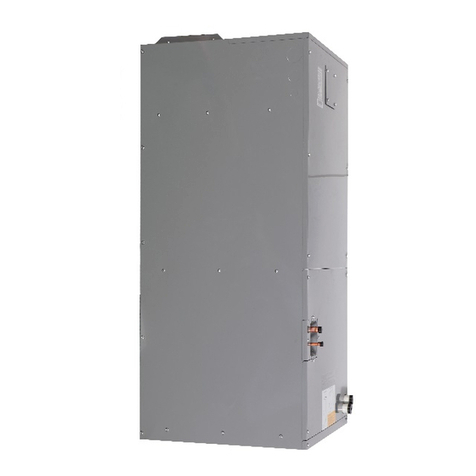
Fig. 1 — Air Handler
NOTE: Read the entire instruction manual before starting the
installation.
TABLE OF CONTENTS
PAGE
SAFETY CONSIDERATIONS ....................................................... 1
INTRODUCTION............................................................................ 2
HEATER PACKAGES .................................................................... 2
DIMENSIONS ................................................................................. 3
INSTALLATION REQUIREMENTS............................................. 4
INSTALLATION............................................................................. 5
Step 1 - Check Equipment................................................................ 5
Step 2 - Mount Unit.......................................................................... 5
Step 3 - Mount Electric Heater (Optional)....................................... 8
Step 4 - Installing Ductwork ............................................................ 11
Step 5 - Condensate Drains .............................................................. 12
Step 6 - Refrigerant Piping............................................................... 13
Step 7 - Evacuate Coil and Tubing System...................................... 15
Step 8 - Electrical Connections ........................................................ 16
INDOOR UNIT WIRING................................................................ 16
WIRING REQUIREMENTS ........................................................... 17
ELECTRICAL DATA ..................................................................... 18
CONNECTION DIAGRAMS ......................................................... 18
Step 9 - Third Party Thermostat Installation.................................... 19
Step 10 - Setting Static Pressure and Airflow .................................. 20
Independent Auxiliary Heat Operation ............................................ 21
FAN PERFORMANCES AT VARYING STATIC PRESSURES . 23
TEST RUN....................................................................................... 26
SYSTEM CHECKS ......................................................................... 26
START-UP PROCEDURES............................................................ 26
TROUBLESHOOTING ................................................................... 27
ADVANCED SERVICE AND INSTALLATION FUNCTIONS .. 27
SAFETY CONSIDERATIONS
Improper installation, adjustment, alteration, service, maintenance, or
use can cause explosion, fire, electrical shock, or other conditions
which may cause death, personal injury or property damage. Consult a
qualified installer, service agency, or your distributor or branch for
information or assistance. The qualified installer or agency must use
factory-authorized kits or accessories when modifying this product.
Refer to the individual instructions packaged with kits or accessories
when installing.
Follow all safety codes. Wear safety glasses, protective clothing and
work gloves. Have a fire extinguisher available. Read these
instructions thoroughly and follow all warnings or cautions included
in the literature and attached to the unit. Consult local building codes
and the current editions of the National Electrical Code (NEC) NFPA
70.
In Canada, refer to the current editions of the Canadian
Electrical Code CSA C22.1. Recognize safety information.
This is the safety-alert symbol . When you see this symbol on the
unit and in instruction manuals, be alert to the potential for personal
injury. Understand the signal words DANGER, WARNING, and
CAUTION. These words are used with the safety-alert symbol.
DANGER identifies the most serious hazards which will result in
severe personal injury or death. WARNING signifies hazards which
could result in personal injury or death. CAUTION is used to identify
unsafe practices which may result in minor personal injury or product
and property damage. NOTE is used to highlight suggestions which
will result in enhanced installation, reliability, or operation.
ELECTRICAL OPERATION HAZARD
Failure to follow this warning could result in personal injury or
death.
Before installing or servicing the unit, always turn off all power to
the unit. There may be more than one disconnect switch. Turn off
accessory heater power if applicable. Lock out and tag switch with
a suitable warning label.
WA R N I N G
CUT HAZARD
Failure to follow this caution may result in personal injury. Sheet
metal parts may have sharp edges or burrs. Use care and wear
appropriate protective clothing and gloves when handling parts.
CAUTION
Installation Instructions
40MBAA Air Handler Unit Ductless System
Sizes 24 to 48

2 Specifications subject to change without notice. IM-40MBAA-03
INTRODUCTION
The Air Handler models are R-410A Fan Coils designed for
installation flexibility allowing multi-position installation Upflow,
down flow, horizontal right & horizontal left. These units leave the
factory compliant with low leak requirements of less than 2% cabinet
leakage rate at 0.5 inches W.C. when tested in accordance with
ASHRAE 193 standard.
The metering device is installed on the outdoor unit and the fan coils
do not have the device. All fan coils have a DC fan motor with
variable speeds for efficiency. The units have been designed for up-
flow, down-flow, and horizontal orientations, including manufactured
and mobile home applications.
These units require a field supplied air filter and electrical disconnect*
and are designed specifically for R-410A refrigerant heat pumps.
These units are available for systems of 24,000 through 48,000 BTUh
nominal cooling capacity (depending on the local codes) See “Step 8 -
Electrical Connections” on page 16.
HEATER PACKAGES
This unit is not equipped with an electric heater package. A factory-
approved, field-installed, ETL listed heater package is available from
your equipment supplier. Factory-authorized, field-installed electric
heater packages are available in sizes 5kW through 20kW. Electric
heaters that are not factory approved could cause damage which
would not be covered under the equipment warranty. Review the
product data literature for all available accessory kits.
Table 1 — Indoor Unit Model Numbers
ACCESSORIES
The system is shipped with the following accessories (see Table 2). Use
all of the installation parts and accessories to install the system. Improper
installation may result in water leakage, electrical shock and fire, or cause
the equipment to fail. Keep the installation manual in a safe place and do
not discard any accessories until the installation has been completed.
Table 2 — Accessories
*The wireless remote is only used to set up the static pressure and
airflow.
NOTE: To use the Wireless Remote for Air Flow Adjustment or
Static Pressure setting, the outer panel and control panel cover
must be removed to make the IR Receiver accessible. See “Step 10
- Setting Static Pressure and Airflow” on page 20.
Fig. 2 — Air Handler
Fig. 3 — Indoor Unit Representation
KBTUH V-PH-HZ ID MODEL NO.
24
208/230-1-60
40MBAAQ24XA3
36 40MBAAQ36XA3
48 40MBAAQ48XA3
EXPLOSION HAZARD
Failure to follow this warning could
result in death, serious personal injury,
and/or property damage.
Never use air or gases containing oxygen
for leak testing or operating refrigerant
compressors. Pressurized mixtures of air
or gases containing oxygen can lead to
an explosion.
WA R N I N G
INSTALLATION
Entrust a licensed contractor to install the unit. Installation by
unskilled persons may lead to improper installation, electric shock,
or fire. Re-installation must be performed by authorized
professionals. Non-compliance may lead to electric shock or fire.
WA R N I N G
This unit is NOT equipped with a single point electrical
connection for an Auxiliary Heat Package. A separate power
supply is required for the Auxiliary Heat Package.
CAUTION
NAME SHAPE QUANTITY
Owner’s and
Installation
Manual
1
Wireless Remote
Controller* 1
Battery 1
Infrared Display Panel
(located in the
Air Handler Unit)
1
ON/OFF
TEMP
FP
TIMER
ON
TIMER
OFF
MODE
FAN/SLC
SLEEP
TURBO
SWING
DIRECT
CLEAN LED
FOLLOW
Air outlet
Air inlet
Drain hose
Refrigerant
connecting
pipe
Coil Compartment
(Access Panel Removed)
Upow Drain Pan
Horizontal Drain Pan

IM-40MBAA-03 Specifications subject to change without notice. 3
DIMENSIONS
Fig. 4 — Dimensions
"
Right Side ViewRear Side View Front View
Bottom View
Top View
E 10.3 [262]
D 18.2 [462]
1.2 [30]
2.2 [55]
2.3 [59]
3.3 [84]
11.8 [299]
13.3 [339]
3.0 [75]
2.5 [64]
4.9 [124]
6.8 [174]
1.7 [44]
A HEIGHT 48.1 [1222]
C WIDTH 19.7 [501]
4.8 [121]
2.4 [61]
6.7 [171]
2.2 [57]
D DUCT 18.2 [462]
E DUCT 10.3 [262]
B DEPTH 21.1 [535]
0.8 [21] 0.5 [13]
0.6 [16] 18.4 [466]
19.7 [500]
Air Outlet
Air Inlet
Ø1.7 [Ø43]
Ø1.3 [Ø34]
Ø0.8 [Ø21]
Ø1.3 [Ø34]
Ø1.7 [Ø43]
Ø0.8 [Ø21]
Filter
Coil
Blower
Nominal Filter Size
20 x 16 x 1 inches
(515 x 442 x 25 mm)
Liquid Line Ø3/8 [Ø9.5]
Gas Line Ø5/8 [Ø16]
L2
L1

4 Specifications subject to change without notice. IM-40MBAA-03
INSTALLATION REQUIREMENTS
Review the following information before installing the unit:
• Do not install the indoor units near a direct source of heat such as
direct sunlight or a heating appliance.
• Allow sufficient space for airflow and unit servicing. See Fig. 6 —
on page 5 for the minimum required distances between the unit and
the walls or ceilings.
• Communication wiring must be at least 3 ft. (1m) away from all
electromagnetic interference (televisions, radios, etc.) sources.
Interference is still possible even if this distance is maintained.
• Ensure any hanger used is strong enough to withstand the unit’s
weight.
• If the indoor unit is installed in an unconditioned space,
running for long periods of time when the temperatures are
outside the recommended indoor unit operation ranges, it is
recommended to seal all the corners of the indoor unit to
prevent any leakage and add insulation material (13/32 to 13/
16 in (10-20 mm)) to the entire surface of the indoor unit to
avoid condensation or heat transfer.
NOTE: Nuisance sweating may occur if the unit is installed in a
high humidity environment with low airflow.
Table 3 — Operating Range
NOTE: DO NOT install the indoor or outdoor units in a location
with special environmental conditions. For those applications,
contact your Ductless representative.
OPERATING RANGE
MIN/MAX °F (°C)
Cooling Heating
Indoor DB 62 / 90 (17 / 32) 32 / 86 (0 / 30)
Indoor WB 59 / 84 (15 / 29)
PRODUCT INSTALLATION
• Installation must be performed by an authorized dealer or
specialist. A defective installation can cause water leakage,
electrical shock, or fire.
• The installation must be performed according to the installation
instructions. Improper installation can cause water leakage,
electrical shock, or fire. (In North America, installation must be
performed in accordance with the requirements of NEC or CEC
by authorized personnel only.)
• Contact an authorized service technician for repair or
maintenance of this unit. This appliance must be installed in
accordance with local codes.
• Only use the included accessories, parts, and specified parts for
installation. Using non-standard parts can cause water leakage,
electrical shock, fire, or unit failure.
• Install drainage piping according to the instructions in this
manual and in accordance with local codes. Improper drainage
may cause water damage to your home and property.
• For units that have an auxiliary electric heater, DO NOT install
the unit within 3 feet (1 meter) of any combustible materials.
•DO NOT install the unit in a location that may be exposed to
combustible gas leaks. If combustible gas accumulates around
the unit, it may cause a fire.
•DO NOT turn on the power until all work has been completed.
• When moving or relocating the system, consult experienced
service technicians for the disconnection and re-installation of
the unit.
WA R N I N G
Securely install the indoor unit on a structure that can sustain its
weight. If the structure is too weak, the unit may fall and cause
personal injury, unit and property damage, or death.
DO NOT install the indoor unit in a bathroom or laundry room as
excessive moisture can short the unit and corrode the wiring.
WARN ING
Install the indoor and outdoor units, cables and wires at least 3.2 ft
(1m) from televisions, routers, computer equipment or radios to
prevent static or image distortion. Depending on the appliances, a
3.2 ft (1m) distance may not be sufficient.
If the indoor unit is installed on metal, it must be electrically
grounded.
CAUTION

IM-40MBAA-03 Specifications subject to change without notice. 5
INSTALLATION
Step 1 - Check Equipment
Unpack the unit and move to the final location. Remove the carton,
taking care not to damage the unit. Inspect the equipment for damage
prior to installation. File a claim with the shipping company if the
shipment is damaged or incomplete. Locate the unit rating plate,
which contains the proper installation information. Check the rating
plate to be sure the unit matches the job specifications.
The indoor unit should be installed in a location that meets the
following requirements:
• Enough room for installation and maintenance
• Enough room for the lineset and drainpipe
• A horizontal ceiling and a structure that can sustain the weight of
the indoor unit
• The air inlet and outlet are not impeded
• There is no direct radiation from heaters
Step 2 -Mount Unit
The unit can stand or lie on the floor, or hang from a ceiling or a wall.
Allow space for wiring, piping, and servicing the unit.
IMPORTANT: When the unit is installed over a finished ceiling and/
or living area, building codes may require a field-supplied secondary
condensate pan to be installed under the entire unit.
Some localities may allow as an alternative, the running of a separate,
secondary condensate line. Consult the local codes for additional
restrictions or precautions.
NOTE: Nuisance sweating may occur if the unit is installed in a
high humidity environment with low airflow.
Fig. 5 — Indoor Unit Dimensions
Table 4 — Indoor Unit Dimensions
Fig. 6 — Installation Clearances
DO NOT install the unit in the following locations:
• Areas with oil drilling or fracking
• Coastal areas with high salt content in the air
• Areas with caustic gases in the air, such as near hot springs
• Areas with power fluctuations, such as factories
• Enclosed spaces, such as cabinets
• Areas with strong electromagnetic waves
• Areas that store flammable materials or gas
• Rooms with high humidity, such as bathrooms or laundry
rooms.
CAUTION
SIZES A B C D E
24-48 48.2in
(1,224mm)
21in
(533mm)
19.6in
(498mm)
18.2in
(461mm)
10.3in
(261mm)
EE
B
C
D
D
A
24in(60.9cm)
24in(60.9cm)
Allow a minimum of 24in (60.9 cm) clearance from access panels.
Vertical Upow Installations
Horizontal Installations

6 Specifications subject to change without notice. IM-40MBAA-03
A. Upflow or Horizontal-Right Installation
The units can be installed in a vertical Upflow or horizontal (right)
configuration.
NOTE: There is no need to change the direction of the
evaporators with Vertical Upflow and Horizontal Right
installations.
Follow these steps to perform a Vertical Upflow installation and
Horizontal Right installation:
1. Open the upper cover.
2. Open the cover of the electronic control box.
3. Connect all necessary wiring according to the wiring diagram.
4. Connect the lineset.
5. Install the drain lines.
Fig. 7 — Vertical Upflow Installations
Fig. 8 — Horizontal Right Installations
NOTE: For a horizontal right installation, secondary condensate
pan (field supplied) must be installed (refer to local codes).
B. Downflow or Horizontal-Left Installation
For the Horizontal Left installation and the Vertical Downflow
installation, the direction of the evaporator should be changed and the
drain pan should be removed first.
Use the following steps to remove the drain pan.
1. Remove the filter cover.
2. Remove the filter.
Fig. 9 — Remove the Filter
3. Open the evaporator cover and remove the drain plug.
Fig. 10 — Open the evaporator cover and remove the
drain plug
Vertical Upow Installations
Horizontal Right Installations
Secondary
Condensate
Pan
Filter

IM-40MBAA-03 Specifications subject to change without notice. 7
4. Remove the drain pan support bracket and the locking clip.
Fig. 11 — Remove the Support Bracket and Clip
5. Remove the pipe temperature sensor and room temperature sensor.
Fig. 12 — Pipe and room temperature sensors
6. Remove the evaporator and drain pan assembly.
Fig. 13 — Rotate the evaporator
7. Rotate the evaporator 180°.
8. Reinstall the evaporator and drain pan assembly.
Fig. 14 — Reinstall the evaporator and drain pan
assembly
9. Reinstall the pipe temperature sensor in its original position. Attach
the room temperature sensor to the evaporator output pipe
protection sleeve.
Fig. 15 — Reinstall the Pipe Temperature Sensor
10. Reinstall the drain pan support bracket and locking clip.
Fig. 16 — Reinstall the Drain Pan Fixed Plate
Remove the lter plate
Bracket
Clip
Room Temperature
Sensor
Pipe Temperature
Sensor
Take out the evaporator
and rotate it 180°
Wiring position of
the room
temperature
sensor
Pipe temperature cable and room
temperature cable pass through the
top of the water intake plate and
the left side plate.
Wiring position
of the pipe
temperature sensor

8 Specifications subject to change without notice. IM-40MBAA-03
11. Reinstall the evaporator cover.
Fig. 17 — Reinstall the Evaporator Cover
12. Reinstall the filter and the filter plate.
Fig. 18 — Reinstall the filter and filter plate
13. Open the lower cover.
14. Open the electronic control box.
15. Connect all the necessary wiring according to the wiring diagram.
16. Connect the lineset.
17. Install the drain lines.
Fig. 19 — Vertical Downflow Installations
Fig. 20 — Horizontal Left Installations
NOTE: For a horizontal left installation, a secondary condensate
pan (field supplied) must be installed (refer to local codes).
Step 3 - Mount Electric Heater (Optional)
Table 5 — Accessories
NOTE: Installation must be performed by an authorized dealer or
specialist. Use recommended PPE when installing the unit.
Specification of electric auxiliary heat modules: 5kW,
10kW, 15kW, 20kW.
If the unit needs to be equipped with the electric auxiliary heat
module, please check the electric auxiliary heat module specification
that is compatible with the unit to avoid unnecessary consequences
caused by improper matching.
INSTALLATION REQUIREMENTS
NOTE: Installation of Auxiliary Electric Heat Module should be
completed before installing the discharge ductwork to insure proper
alignment of the inside support brackets.
Before installation, check the list of electric auxiliary heat modules
and physical objects. After transportation, check whether the electric
heat module is damaged. If any damage is detected, contact the after-
sales personnel immediately.
NOTE: A separate power source is required for an Auxiliary
Electric Heater. These units do NOT support a SINGLE POINT
electrical connection.
Vertical Downow Installations
Horizontal Left Installations
Secondary
Condensate Pan
(check local codes)
NAME SHAPE QUANTITY
Owner’s and
Installation Manual 1
Seal 1
Screw 2
Resilient Cap 1
Electric Auxiliary
Heating Wiring
Diagram
1
Circuit Breaker
Label 1
The electric auxiliary heat module is internally mounted in the air
handler. DO NOT MOUNT IN DUCTWORK!
CAUTION

IM-40MBAA-03 Specifications subject to change without notice. 9
ELECTRIC AUXILIARY HEAT MODULE
INSTALLATION AND WIRING
1. Remove the six screws securing the upper cover plate and the
chassis.
Fig. 21 — Upper Cover Plate
2. Remove the four screws securing the electric auxiliary heat cover
plate and the upper cover plate.
Fig. 22 — Electric Auxiliary Heat Module Plate
3. Remove the screws and the sheet-metal cover(s) reserved for the
electric heating module.
NOTES:
• For model 5KW, 10KW, remove three screws from the upper
sheet metal cover only.
• For model 15Kw, 20KW, remove the upper and lower sheet
metal covers.
Fig. 23 — Remove Sheet Metal Covers
4. Insert the heating module into the opening made by removal of the
sheet metal cover(s). Ensure the two support rod ends are on the
opposite bulkhead.
Fig. 24 — Insert Heating Module
5. Use the 3 screws (6 screws for 15K or 20K) removed previously
and fasten the outer cover of the module into the access hole.
Fig. 25 — Install the Electric Heating Module
6. Secure one end of the electric heating terminal board to the sheet
metal slot close to the fan, and the other end to the sheet metal on
the top cover plate with two screws.
7. Secure the 2 tabs on the Power Terminal mounting bracket in the
slots provided and fasten the lower tabs with 2 screws.
Fig. 26 — Electrical Heating Terminal
8. Remove the cover for the electronic controls. After completing the
following steps, the cover needs to be re-installed.
Fig. 27 — Remove the electronic control box
Lower Sheet Metal Cover
Upper Sheet Metal Cover

10 Specifications subject to change without notice. IM-40MBAA-03
9. Insert the white plug of the electric heating control line into the
electric control box through the reserved crossing hole and insert
into the corresponding white plug in the electronic control box.
Fig. 28 — Insert the white plug wire
10. Connect the low voltage control wire (W2) of the third party
thermostat to the AUX terminal of the 24 volt interface (does not
matter which terminal). Figure 29 shows the interface board AUX
terminal.
NOTE: The control wire may be connected to the AUX terminals
in any order.
Fig. 29 — Connect the auxiliary heat wire
11. Power Wiring should be sized in accordance with NEC (CEC)
requirements and local codes (see Table 6 on page 11). Choose the
power cord and the power cord installation location (see Figure 30).
Each circuit breaker group needs to connect to the power input line.
Where needed, Jumper L1 and L2 to the terminals for the other
contactor.
Fig. 30 — Choose the power cord installation
location
12. See Figure 31 for the securing position of the power supply ground
wire. Secure the power input wires for each group, and make sure
that the cable is properly grounded.
Fig. 31 — Secure the power input wires of each
group
NOTE: After installing the electric auxiliary heat module, place
the circuit breaker label near the upper cover circuit breaker.
Fig. 32 — Circuit Breaker Label Placement
13. Remove the resilient cap and seal from the auxiliary heat module
accessory bag, and attach the seal to the resilient cap.
Fig. 33 — Remove the resilient cap

IM-40MBAA-03 Specifications subject to change without notice. 11
14. Fasten the resilient cap and seal on the upper cover plate with 4
screws.
Fig. 34 — Fasten the resilient cap
15. Reassemble the electronic control cover and secure it with screws.
Reassemble the upper cover plate and secure it with screws. After
the electric heating wiring is connected, confirm the plate is secure
before powering the unit on. Check all the wiring and ensure a
reliable connection with the wire body.
Table 6 — Specifications
Fig. 35 — Indoor Unit Wiring Diagram
NOTE:
The electric auxiliary heat wiring diagram is supplied with the
accessories. Please paste the wiring diagram in the designated position
after installing the heat modules.
Step 4 - Installing Ductwork
Connect the supply-air duct over the outside of the 3/4in (19 mm)
flanges provided on the supply-air opening. Secure the duct to the
flange, using proper fasteners for the type of duct used, and seal duct-
to-unit joint. If the return-air flanges are required, install the factory-
authorized accessory kit.
Use flexible connectors between the ductwork and unit to prevent
transmission of vibration. When the electric heater is installed, use
heat-resistant material for the flexible connector between the
ductwork and the unit at the discharge connection. Ductwork passing
through the unconditioned space must be insulated and covered with a
vapor barrier.
Units equipped with 20kW electric heaters require a 1in (25mm)
clearance to combustible materials for the first 36in (914mm) of
supply duct.
DUCTWORK ACOUSTICAL TREATMENT
Metal duct systems that do not have a 90 degree elbow and 10ft (3m) of
main duct to first branch takeoff may require internal acoustical insulation
lining. As an alternative, fibrous ductwork may be used if constructed and
installed in accordance with the latest edition of the SMACNA
construction standard on fibrous glass ducts. Both acoustical lining and
fibrous ductwork shall comply with the National Fire Protection
Association as tested by UL Standard 181 for Class 1 air ducts.
The air supply and return may be handled in one of several ways;
whichever situation is best suited for the installation (See Fig. 5 — on
page 5). A large number of issues encountered with split-system
installations can be linked to improperly designed or installed duct
systems. It is therefore very important that the duct system be properly
designed and installed.
Use of flexible duct collars is recommended to minimize the transmission
of vibration/noise into the conditioned space. Where the return air duct is
short, or where sound is liable to be a problem, sound absorbing glass fiber
should be used inside the duct.
Insulation of duct work must be installed according to local codes and
best practices. The supply air duct should be properly sized by use of a
transition to match unit opening.
This unit is not designed for non-ducted (freeblow) applications. Duct
work should be fabricated and installed in accordance with local and/
or national codes.
Fig. 36 — Flexible Duct Collar Connection
Specifications
No. of
Circuit
Breakers
No. of
Relays
No. of
Power
Cord
Groups
No. of
Power
Cord
Grounding
Screws
5kW 1111
10kW 1211
15kW 2322
20kW 2422
Indoor unit wiring diagram
Electric auxiliary
heat wiring diagram
Plenum Clearances
MINIMUM CLEARANCE
OF 1ft (25.4mm) ALL SIDES
RECOMMENDED FLEXIBLE
DUCT COLLAR
3.2ft (1m)

12 Specifications subject to change without notice. IM-40MBAA-03
Step 5 - Condensate Drains
The drainpipe is used to drain water away from the unit. Improper
installation may cause unit and property damage.
NOTE: Installation requires adapting the locally sourced drain line to
a 3/4” NPT female pipe thread connection.
INDOOR DRAINPIPE INSTALLATION
1. Cover the drainpipe with insulation, as required, to prevent
condensation and leakage. These units operate with a positive
pressure at the drain connection and a drain trap is required. The
trap needs to be installed as close to the unit as possible. Ensure the
top of the trap is below the connection to the drain pan to allow
complete drainage of the pan.
Fig. 37 — Vertical Discharge
NOTE: Horizontal runs must also have a drain trap installed ahead
of the horizontal run to eliminate air trapping.
Fig. 38 — Primary Drain
NOTES: When using an extended drainpipe, tighten the indoor
connection with an additional protection tube to prevent it from
pulling loose.
Figure 37 shows how to trap or plug all drains to provide a a vertical
discharge. Figure 38 shows how to trap or plug all drains to provide a
right-hand discharge.
Hand tighten the plug(s) for drain holes that are unused.
Incorrect installation could cause water to flow back into the unit and
flood.
2. Use a 2.5in (65mm) core drill to drill a hole in the wall. Make sure
the hole is drilled at a slight downward angle, so that the outdoor
end of the hole is lower than the indoor end by about 0.5in (12mm).
This will ensure proper water drainage. Place the protective wall
cuff in the hole. This protects the edges of the hole and helps seal
the hole once the installation is complete.
Fig. 39 — Drill hole
NOTE: When drilling the hole, make sure to avoid wires, plumbing,
and other sensitive components.
3. Pass the drain hose through the wall hole. Make sure the water
drains to a safe location where it will not cause water damage or a
slipping hazard.
NOTE: The drainpipe outlet should be at least 2in(5cm) above the
ground. If it touches the ground, the unit may become blocked
and malfunction. If you discharge the water directly into a sewer,
make sure that the drain has a U or S pipe to catch odors that
might otherwise come back into the house. Follow the local
plumbing codes.
• Insulate all piping to prevent condensation, which could lead to
water damage. Check the local codes.
• If the drainpipe is bent or installed incorrectly, water may leak
and cause a water-level switch malfunction.
• In HEAT mode, the outdoor unit may discharge water. Ensure
that the outdoor drain will not contribute to damage and
slippage.
• DO NOT pull the drainpipe forcefully. This could disconnect it.
CAUTION
VERTICAL DISCHARGE
PRIMARY DRAIN
≥5°
Install a drain trap per the local codes
PRIMARY DRAIN
Wall
IndoorOutdoor
≈ 0.5 in.(12mm)

IM-40MBAA-03 Specifications subject to change without notice. 13
Step 6 - Refrigerant Piping
IMPORTANT: Both refrigerant lines must be insulated separately.
• The minimum refrigerant line length between the indoor and
outdoor units is 10 ft. (3 m).
• Table 7 lists the pipe sizes for the indoor unit. Refer to the outdoor
unit’s installation instructions for the additional allowed piping
lengths and refrigerant information.
• Refer to the outdoor unit’s installation manual for details regarding
the allowable pipe length and height difference.
Table 7 — Piping Size
Use the following steps to connect the refrigerant piping:
1. Run the interconnecting piping from the outdoor unit to the indoor
unit.
2. Connect the refrigerant piping and drain line outside the indoor
unit. Complete the pipe insulation at the flare connection then
fasten the piping and wiring to the wall as required. Completely seal
the hole in the wall.
3. Cut tubing to correct length.
When preparing refrigerant pipes, take extra care to cut and
flare them properly. This ensures efficient operation and
minimizes the need for future maintenance.
a. Measure the distance between the indoor and outdoor units.
b. Using a pipe cutter, cut the pipe a little longer than the
measured distance.
c. Make sure the pipe is cut at a perfect 90° angle.
Fig. 40 — Pipe Cutting
4. Remove Burrs
Burrs can affect the air-tight seal of the refrigerant piping
connection. Therefore, they must be completely removed. To
remove:
a. Hold the pipe at a downward angle to prevent burrs from falling
into the pipe.
b. Using a reamer or deburring tool, remove all burrs from the cut
section of the pipe.
Fig. 41 — Deburring tool
5. Flare Pipe Ends
Proper flaring is essential to achieving an airtight seal.
a. After removing the burrs from the cut pipe, seal the ends with
PVC tape to prevent foreign materials from entering the pipe.
b. Sheath the pipe with insulating material.
c. Place flare nuts on both ends of the pipe. Make sure they are
facing the right direction. Once the ends are flared, it is
impossible to put them on or change their direction.
Fig. 42 — Copper pipe and flare nut
d. Remove the PVC tape from ends of pipe when ready to perform
the flaring work.
24K 36K 48K
Gas Pipe
(Connection Size) In (mm) 5/8 (16) 5/8 (16) 5/8 (16)
Liquid Pipe
(Connection Size) In (mm) 3/8 (9.52) 3/8 (9.52) 3/8 (9.52)
All field piping must be completed by a licensed technician and
must comply with the local and national regulations.
When the system is installed in a small room, measures must be
taken to prevent the refrigerant concentration in the room from
exceeding the safety limit in the event of refrigerant leakage. If the
refrigerant leaks and its concentration exceeds its proper limit,
hazards due to lack of oxygen may result.
When installing the refrigeration system, ensure that air, dust,
moisture or foreign substances do not enter the refrigerant circuit.
Contamination in the system may cause poor operating capacity,
high pressure in the refrigeration cycle, explosion or injury.
Ventilate the area immediately if there is refrigerant leakage
during the installation.
Leaked refrigerant gas is hazardous. Ensure there is no refrigerant
leakage after completing the installation work.
WA R N I N G
DO NOT install the connecting pipe until both the indoor and
outdoor units have been installed.
Insulate both the gas and liquid piping to prevent condensation.
CAUTION
Oblique Rough Warped
90°
DO NOT DEFORM PIPE WHILE CUTTING
Be extra careful not to damage, dent, or deform the pipe while
cutting. This will drastically reduce the heating efficiency of the
unit.
CAUTION
Pipe
Reamer
Point down
Flare nut
Copper pipe

14 Specifications subject to change without notice. IM-40MBAA-03
e. Clamp the flare block on the end of the pipe. The end of the
pipe must extend beyond the flare form.
Fig. 43 — Flare Block
f. Place the flaring tool onto the form.
g. Turn the handle of the flaring tool clockwise until the pipe is fully
flared. Flare the pipe in accordance with the dimensions in Table 8
on page 14.
Fig. 44 —Flare Shape
h. Remove the flaring tool and flare block, then inspect the end of
the pipe for cracks and even flaring.
Table 8 — Flare Nut Spacing
6. Connect the Pipes
Connect the copper pipes to the outdoor unit first, then connect
the pipes to the indoor unit. Connect the low-pressure pipe first,
then connect the high pressure pipe.
1. When connecting the flare nuts, apply a thin coat of refrigeration oil
to the flared ends of the pipes.
2. Align the center of the two pipes that you will connect.
Fig. 45 — Align the center of the two pipes
3. Tighten the flare nut as much as possible by hand.
4. Using a wrench, grip the nut on the unit tubing.
5. While firmly gripping the nut, use a torque wrench to tighten the
flare nut according to the torque values listed in Table 9.
Table 9 — Tightening Torque
NOTE: Use both a backup wrench and a torque wrench when
connecting or disconnecting pipes to or from the unit.
Fig. 46 — Torque wrench with backup wrench
All tubing bends should be performed with a properly sized tubing
bender to prevent kinking or damaging the tubing.
6. After connecting the copper pipes to the outdoor unit, wrap the
power cable, signal cable and the piping together with binding tape.
NOTE: While bundling these items together, DO NOT intertwine
or cross the signal cable with any other wiring.
7. Thread this lineset through the wall to connect to the indoor unit.
8. The liquid line sweat connection is 3/8” O.D. copper and the
suction line sweat connection is 5/8” O.D. copper. Use the
appropriate adapters for tubing that runs from the outdoor unit. Cut
and deburr the tubing (review “Remove Burrs” on page 13) to
prepare it for brazing. Setup the nitrogen apparatus and connect to
the outside unit to flow nitrogen while brazing. Braze the tubing
and any fittings to obtain a proper seal.
9. Adjust the nitrogen apparatus to pressurize the system. Pressure test
the system to a maximum of 500 psig for at least 60 minutes.
10. Insulate both lines of the line set separately and completely,
including the outdoor unit valves.
OUTER DIAM. (MM) A IN (MM)
MAX. MIN.
Ø 3/8”(9.52) 0.06”(1.6) 0.04”(1.0)
Ø 1/2”(12.7) 0.07”(1.8) 0.04”(1.0)
Ø 5/8”(15.88) 0.09”(2.2) 0.08”(2.0)
BRASS FLARE SIZE
RECOMMENDED SEATING
TORQUE FOR BRASS
FLARE NUTS
N-M
Ø3/8 15-18 Ft. - Lbs 20.3 to 24.4
Ø1/2 28-32 Ft. - Lbs 38.0 to 43.4
Ø5/8 38-42 Ft. - Lbs 51.5 to 56.9
Flare block
Pipe
R0.4~0.8
45qr2
90 q
r4
A
Pipe
Indoor unit tubing Flare nut
Wrap insulation around the piping. Direct contact with the bare
piping may result in burns or frostbite. Ensure the pipe is properly
connected. Over tightening may damage the bell mouth and under
tightening may lead to leakage.
CAUTION

IM-40MBAA-03 Specifications subject to change without notice. 15
Step 7 - Evacuate Coil and Tubing System
Refrigerant tubes and the indoor coil should be evacuated using the
recommended 500 microns deep vacuum method. The alternate triple
evacuation method may be used if the procedure outlined below is
followed.
NOTE: Always break a vacuum with dry nitrogen.
Using Vacuum Pump
1. Completely tighten flare nuts A, B, C, D, connect the manifold
gage charge hose to a charge port of the low side service valve (see
Fig. 47).
2. Connect the charge hose to vacuum pump.
3. Fully open the low side of manifold gage (see Fig. 48).
4. Start the vacuum pump.
5. Evacuate using either the deep vacuum or triple evacuation method.
6. After evacuation is complete, fully close the low side of manifold
gage and stop the vacuum pump operation.
7. The factory charge contained in the outdoor unit is good for up to
25 ft. (8 m) of line length. For refrigerant lines longer than 25 ft. (8
m), add refrigerant, up to the allowable length.
8. Disconnect the charge hose from the charge connection of the low
side service valve.
9. Fully open service valves B and A.
10. Securely tighten the service valve caps.
Fig. 47 — Service Valve
Fig. 48 — Manifold
Evacuation
Evacuation of the system will remove air or nitrogen (non-condensables)
as well as moisture. A proper vacuum will assure a tight, dry system
before charging with refrigerant. The two methods used to evacuate a
system are the deep vacuum method and the triple vacuum method.
Deep Vacuum Method
The deep vacuum method requires a vacuum pump capable of pulling
a vacuum of 500 microns and a vacuum gauge capable of accurately
measuring this vacuum depth. The deep vacuum method is the most
positive way of assuring a system is free of air and moisture (see Fig.
49).
NOTE: DO NOT add a filter line drier.
Fig. 49 — Deep Vacuum Graph
Triple Evacuation Method
The triple evacuation method should be used when vacuum pump is
not capable of pumping down to 500 microns and system does not
contain any liquid water. Refer to Fig. 50 and proceed as follows:
1. Attach refrigeration gauges and evacuate system down to 28 in. of
mercury and allow pump to continue operating for an additional 15
minutes.
2. Close service valves and shut off vacuum pump.
3. Connect a nitrogen cylinder and regulator to system and flow
nitrogen until system pressure is 2 psig.
4. Close service valve and allow system to stand for 1 hour. During
this time, dry nitrogen can diffuse throughout the system absorbing
moisture.
5. Repeat this procedure as indicated in Fig. 50. The system should
now be free of any contaminants and water vapor.
Fig. 50 — Triple Evacuation Method
Final Tubing Check
IMPORTANT: Check to be certain factory tubing on both the
indoor and outdoor unit has not shifted during shipment. Ensure
tubes are not rubbing against each other or any sheet metal. Pay
close attention to the feeder tubes, making sure wire ties on feeder
tubes are secure and tight.
UNIT DAMAGE HAZARD
Failure to follow this caution may result in equipment damage
or improper operation.
Never use the system compressor as a vacuum pump.
CAUTION
Outdoor Unit Indoor UnitRefrigerant
Service Valve
Low Side
High Side
A
B
C
D
500 microns
Low side valve
High side valve
Charge hose
Charge hose
Vacuum
pump
Low side valve
500
MINUTES
01234567
1000
1500
LEAK IN
SYSTEM
VACUUM
TIGHT
TOO WET
TIGHT
DRY SYSTEM
2000
MICRONS
2500
3000
3500
4000
4500
5000
CHECK FOR TIGHT, DRY SYSTEM
(IF IT HOLDS DEEP VACUUM)
EVACUATE
BREAK VACUUM WITH DRY NITROGEN
WAIT
EVACUATE
RELEASE CHARGE INTO SYSTEM
BREAK VACUUM WITH DRY NITROGEN
EVACUATE
WAIT

16 Specifications subject to change without notice. IM-40MBAA-03
Step 8 - Electrical Connections
Before proceeding with electrical connections, make certain that the
supply voltage, frequency, phase, and ampacity are as specified on the
unit rating plate. Review the unit wiring label for proper field high and
low voltage wiring.
Ensure all electrical connections are in accordance with the NEC and
any local codes or ordinances that may apply. Use copper wire only.
INDOOR UNIT WIRING
Use the following steps to wire the indoor unit.
1. Prepare the cable for connection.
a. Using wire strippers, strip the insulation from both ends of
the signal cable to reveal about 1/2 in (12mm) of wire.
b. Strip the insulation from both ends of the wires.
c. Use a wire crimper to crimp the fork terminals to the ends
of the wires.
2. Open the indoor unit’s front panel. Use a screwdriver to remove the
cover of the electric control box on the indoor unit.
3. Thread the power cable and the signal cable through the wire outlet.
4. Connect the fork terminals to the terminals. Match the wire colors/
labels with the labels on the terminal block.
5. Firmly screw the fork terminals of each wire to its corresponding
terminal. Refer to the serial number and wiring diagram located on
the cover of the electric control box.
Fig. 51 — Control Box and Wiring Diagram
6. Clamp down the cable with the cable clamp. The cable must not be
loose or put strain on the fork terminals.
7. Reattach the electric box cover.
Fig. 52 — Ferrite Core (Magnetic Ring)
The main power is supplied to the outdoor unit. When disconnecting
the power of the outdoor unit, the indoor unit would lose power. A
disconnect switch is not required on the indoor unit side on the wiring
between the outdoor and indoor unit. A 3 pole disconnect (purchased
separately) may be used for extra protection between the indoor and
outdoor Unit.
Fig. 53 — Wiring Connection of Indoor Unit
The Auxiliary Heater must have a separate branch electric circuit with
a field-supplied disconnect switch located within sight from, and
readily accessible from, the unit.
Fig. 54 — Wiring Connection of Electric Heater
(optional)
PROPERTY DAMAGE HAZARD
Failure to follow this caution may result in product or property
damage.
If a disconnect switch is to be mounted on the unit, select a
location where the drill or fastener will not contact electrical or
refrigerant components.
CAUTION
ELECTRICAL SHOCK HAZARD
Failure to follow this warning could result in personal injury or
death.
Field wires on the line side of the disconnect found in the fan coil
unit remain live, even when the pull-out is removed.
Service and maintenance to incoming wiring cannot be performed
until the main disconnect switch (remote to the unit) is turned off.
WARN ING
EQUIPMENT DAMAGE HAZARD
Failure to follow this caution may result in equipment damage or
improper operation. Size the wires in accordance with NEC and
local codes.
CAUTION
Wiring Diagram
Control Box
While connecting the wires, strictly follow the wiring diagram.
The refrigerant circuit can become very hot.
Keep the interconnection cable away from the copper tube.
CAUTION
L1 L2 S
Pass the belt through the hole
of the ferrite core
(Magnetic Ring)
to secure it to the cable
Circuit Breaker
3 Pole Disconnect
(purchased separately)
Electrical heater unit power wires
Electrical
heater
unit
Circuit Breaker
(DO NOT
connect to
the indoor unit
circuit breaker!)

IM-40MBAA-03 Specifications subject to change without notice. 17
WIRING REQUIREMENTS
Size all wires per the NEC (National Electrical Code) or CEC
(Canadian Electrical Code) and local codes. Use the electrical data
from the outdoor unit (MCA - minimum circuit amps and MOCP -
maximum over current protection), to correctly size the wires and the
disconnect fuse or breakers respectively.
SIZE 24 RECOMMENDED CONNECTION METHOD
FOR POWER AND COMMUNICATION WIRING
Power and Communication Wiring: The main power is supplied to
the outdoor unit. The field supplied 14/3 power/communication
wiring, from the outdoor unit to the indoor unit, consists of four (4)
wires and provides the power for the indoor unit. Two wires are high
voltage AC power, one is communication wiring and the other is a
ground wire.
To minimize communication interference: If installed in a high
Electromagnetic field (EMF) area and communication issues arise, a
14/2 stranded shielded cable can be used to replace L2 and (S)
between the outdoor and indoor units - landing the shield onto the
ground in the outdoor unit only.
Table 10 — Wiring Size 24
SIZES 36-48 RECOMMENDED CONNECTION METHOD
FOR POWER AND COMMUNICATION WIRING
Power and Communication Wiring: The main power is supplied to
the outdoor unit. The field supplied power wiring from the outdoor
unit to the indoor unit consists of three (3) wires and provides the
power for the indoor unit. Two wires are high voltage AC power and
one is a ground wire. To minimize voltage drop, the factory
recommended wire size is 14/2 power stranded with a ground.
Communication Wiring: A separate 2-wire cable (stranded,
shielded, copper conductor), with a 600 volt rating and double
insulated copper wire, must be used as the communication wire from
the outdoor unit to the indoor unit.
Please use a separate shielded 16AWG stranded control wire.
Table 11 — Wiring Sizes 36-48
NOTE: The main power is supplied to the outdoor unit. When
disconnecting the power of the outdoor unit, the indoor unit
would lose power. A disconnect switch is not required on the
Indoor unit side on the wiring between the Outdoor and Indoor
unit. A 3 pole disconnect may be used for extra protection
between the indoor and outdoor unit (refer to local codes). A
separate power source is required for an auxiliary electric heater.
CABLE CABLE SIZE REMARKS
Connection
Cable 14AWG 3 wire + Ground 1Φ208/230 V
(Stranded wire is required)
CABLE CABLE SIZE REMARKS
Power
Connection
Cable
14AWG 2 wire + Ground 1Φ208/230 V
Communication
Cable 16AWG 2 wire stranded shielded control
wire
EQUIPMENT DAMAGE HAZARD
Be sure to comply with local codes while running wire from the
indoor unit to the outdoor unit.
Every wire must be connected firmly. Loose wiring may cause the
terminal to overheat or result in a unit malfunction. A fire hazard
may also exist. Ensure all wiring is tightly connected.
No wire should touch the refrigerant tubing, compressor or any
moving parts.
Disconnecting means must be provided and located within sight
and readily accessible from the system. Route the connecting
cable with conduit through the hole in the conduit panel.
CAUTION

18 Specifications subject to change without notice. IM-40MBAA-03
ELECTRICAL DATA
Table 12 — Electrical Data
CONNECTION DIAGRAMS
Fig. 55 — Connection Diagram (size 24K)
Fig. 56 — Connection Diagram (sizes 36K and 48K)
Fig. 57 — Control and Power Terminal on Indoor Unit (size 24K)
Fig. 58 — Control and Power Terminals on Indoor Unit (sizes 36K to 48K)
UNIT SIZE INDOOR FAN MAX FUSE CB AMP
V-PH-HZ FLA HP W
Refer to outdoor unit installation instructions –
Indoor unit powered by the outdoor unit
24
208-230/1/60
5 0.20 120
36 5 0.42 250
48 5 0.65 400
3(S)
1(L1) 2(L2)
208-230-1-60
Power Supply
Main
1(L1)
208-230-1-60
2(L2) 3(S) 1(L1) 2 (L2)
CONNECTING CABLE
OUTDOOR TO INDOOR
Indoor Unit
Power Supply
208-230-1-60
Indoor
Signal
High
GND
Ground Power to
Indoor Unit
208-230-1-60
GND
FIELD POWER SUPPL
Y
Voltage
Indoor
SignaLl
High
Voltage
208-230-1-60
L1 L2
FIELD POWER SUPPLY
Indoor Unit
Power Supply
Low voltage
Nonpolar RS-485
communication
208-230-1-60
Nonpolar RS-485
Low voltage
communication
Outdoor Unit
208-230-1-60
Power Supply
SHIELDED WIRE CONNECTING
OUTDOOR TO INDOOR
To Indoor Unit
Power Supply
S1 S2
L1
L1 L2
L2
(S1)
GND
(S2)
CONNECTING CABLE
OUTDOOR TO INDOOR
L1(1) L2(2) S(3)
CN 8 on
24V Interface

IM-40MBAA-03 Specifications subject to change without notice. 19
Step 9 - Third Party Thermostat Installation
The indoor unit has a 24V transformer that provides flexibility,
functionality and control by a 3rd party thermostat* (field supplied).
1. Run the thermostat wiring from the thermostat to the 24V interface
using connection R and C on CN15 and Y, W, G on CN19. see Fig.
64.
2. The 24V Interface Dip Switches come pre-configured for normal
operation and easy installation. Dip Switch 2-1 can be configured to
make the system operate in the COOLING ONLY mode. Dip
Switch 3-1 can be configured for the DRY mode when not using
auxiliary heat.
Table 13 — DIP Switch 2-1
Table 14 — DIP Switch 3-1
3. Configure the thermostat to operate as a single stage cooling and
heating (DO NOT configure the thermostat as Heat Pump).
*A conventional 5-wire thermostat is required. A 2 Heat/ 1 Cool thermostat is
required for electric heat application.
Fig. 59 — Indoor Unit Control Box Size 24
Fig. 60 — Indoor Unit Control Box Sizes 36 - 48
LED Display
The control displays active faults codes on the LED display. When the
control displays the fault code and the LED flashes quickly, there is
something wrong with the system. Refer to
“TROUBLESHOOTING”on page 27 for the detailed fault codes.
Temperature Sensor
The unit has one temperature sensor, which is called a Pipe
Temperature Sensor. If the temperature sensor is damaged, the system
shuts down and the LED flashes repeatedly.
Connector
Table 15 — Connector
Table 16 — Mode Setting
Table 17 — Fan Speed Setting
Fig. 61 — Cooling Only System Wiring Diagram
SW2-1 RESULT NOTE
ON COOLING ONLY
OFF HEAT PUMP Default
SW3-1 RESULT NOTE
ON DRY Mode
OFF Used on future
applications Default
24V Board
Main Board
Main Terminal Board
Main
Board
24V
Interface
Board
24V Transformer
Connector Purpose
Y Cooling
W Heating
G Fan-Auto Speed
AUX/DRY Aux-Heat/Dry
Y W G AUX/DRY SETTING MODE
√X * * Cooling
X√* X Heating (without aux-heater)
X√*√Heating (with aux-heater)
XX√X Fan only
√√** OFF
XXX X OFF
XX * √Dry
UNIT ON/OFF G SETTING FAN SPEED
√X Auto Fan Speed
√√Auto Fan Speed
X X Fan OFF
√ON
XOFF
*ONorOFF
INDOOR UNIT OUTPUT WITH 24VAC 1.5A
INDOOR UNIT
THERMOSTAT

20 Specifications subject to change without notice. IM-40MBAA-03
Fig. 62 — Cooling and Heating System Wiring
Diagram
Fig. 63 — Cooling and Heating Units Adopt Electric
Heating Device
Fig. 64 — 24V Thermostat Wiring Diagram
Step 10 - Setting Static Pressure and Airflow
NOTE: Remove the middle panel from the unit and the control
panel cover to allow access to the IR Receiver.
The indoor fan coil units can be programmed to have different static pressures
settings or airflows; the factory default setting is SP1 (see “FAN
PERFORMANCES AT VARYING STATIC PRESSURES”on page 23).
Follow the next steps to set the
static pressure
or
Automatic Airflow
using
the Wireless Remote Controller according to the installation conditions.
• The external static pressure can be manually changed to the fan
curves SP1, SP2, SP3, SP4.
• Choose the Automatic Airflow
“AF”
adjustment function to
automatically identify the static pressure and regulate the airflow amount.
Follow these instructions to configure:
1. Ensure the test run is done with a dry coil. If the coil is not dry, run
the unit for 2 hours in the FAN ONLY mode to dry the coil.
2. Check that both the power supply wiring and the duct installation have been
completed. Check that the supply air vent is properly positioned. Check that
the air filter is properly attached to the air return side passage of the unit.
3. If there is more than one air inlet and/or outlet, adjust the dampers
so that the airflow rate of each air inlet and outlet conforms to the
designed airflow rate. The wireless remote controller is required to
setup the static pressure of the indoor air handler units.
NOTE: When a system is using the 24V interface built-in, the indoor
unit’s fan speed defaults to AUTO with the indoor unit’s default logic.
The external static pressure should be selected using the wireless remote
controller (RG57F3(B)/BGEFU1), included with the indoor unit, by pointing
it toward the indoor unit’s Infrared Receiver located inside the control box.
a. Before using the service functions of the remote, turn OFF
the thermostat if connected.
b. Turn off the power to the indoor and outdoor units for 3
minutes.
c. Turn the power back on. Wait 1 minute and check the 24
volt Interface digital display. If the display reads “00”, then
proceed. If not, make sure that the thermostat is turned OFF.
d. Remove the batteries from the RG57 wireless remote
controller and wait for the remote screen to clear or press
any button and the screen clears.
e. Reinstall the batteries.
f. Within 30 seconds of replacing the batteries, simultaneously press
MODE
and
TIMER ON
for five (5) seconds. You are now in the
SERVICE FUNCTION
mode – and the remote display reads
F1
.
g. Manual static pressure or AUTOMATIC AIRFLOW
ADJUSTMENT selection:
1. For manual static pressure selection, press the
DOWN
arrow in
the center of the remote (labeled
TEMP
) to display
E9
. Press
MODE
to set the external static pressure/airflow rate in the
range of 1~4. Press
TIMER ON
to confirm.
NOTE: Reinstall
the middle panel and leave in place while the fan is running
to set the fan curve.
The values on the remote controller
(
1,2,3,4
) correlate directly to the static pressure curves
SP1,
SP2, SP3, SP4
(See “FAN PERFORMANCES AT VARYING
STATIC PRESSURES” on page 23). After selecting speed
power off the outdoor unit for 3 minutes to lock in the change.
2. If choosing the
AUTOMATIC AIRFLOW ADJUSTMENT
function, with F1 in the remote display, press the
DOWN
arrow
once and
d4
appears. Press
TIMER ON
to confirm.
NOTE:
Reinstall the middle panel and leave in place while the fan is
running to establish automatic air flow adjustment
.
AF
appears in the unit’s LED display. The system starts the fan for
the airflow automatic adjustment. The
ON
indicator flashes
when the fan runs during the
AUTOMATIC AIRFLOW
ADJUSTMENT
. After 3 to 6 minutes, the system stops
operating once the
AUTOMATIC AIRFLOW
ADJUSTMENT
is complete.
h. Remove the remote controller battery, and then re-insert the
battery after the remote controller screen goes blank. The
remote controller exits the SERVICE FUNCTION mode.
INDOOR UNIT OUTPUT WITH 24VAC 1.5A
INDOOR UNIT
THERMOSTAT
INDOOR UNIT
THERMOSTAT
Aux Aux
BLUE
RED
YELLOW
GREEN
WHITE
BROWN
CN15
R C
CN18 CN19
G1 G2 G3 Y W G
24V R
24V C
Cool
Heat
Auto_Fan
Aux/Dry
CN22
24V THERMOSTAT
Table of contents
Other Midea Air Handler manuals
Popular Air Handler manuals by other brands

AAON
AAON RQ NextGen Series Installation operation & maintenance

aerauliqa
aerauliqa AIRQURE P1 Installation, use and maintenance manual

Envistar
Envistar Flex ENF Assembly instructions

ALORAIR
ALORAIR Cleanshield HEPA 550 owner's manual

Trane
Trane TWE031E13FB1 Installer's guide

AirScape
AirScape Make-Up Air Unit Installation and operation manual