IFM Electronic ASinterface AS-i AirBox 32 V2A AC2055 User manual

Montageanleitung
Installation instructions
Notice de montage
AS-i AirBox 32 V2A
AC2055
Sachnr. 701347/04 03/ 2004 Teile-Nr. 80.280

Bestimmungsgemäße Verwendung
Die AS-i AirBox fungiert als Slave im AS-i-Netz (AS-i-Profil S 7.F). Sie
verbindet zwei Doppelsensoren und zwei pneumatische Ausgänge mit
dem AS-i-Master.
• Sensorversorgung integriert (insgesamt 100mA pro Modul)
• Sensoranschluß über Steckverbindung
• AS-i Anschluß über EMS Modul-Unterteil
• Verbindung mit Pneumatik-System über Schlauchsteckverbinder
Legris 3000/8mm, außenkalibriert nach CETOP-Norm RP 54 P
• Betrieb mit Druckluft von 2...8bar inklusive möglicher Druckspitzen
(Druckspitzen > 8bar können dauerhafte Undichtigkeiten bzw. irre-
parable Beschädigungen an der AirBox verursachen)
• Handbetätigung tastend oder drückend-drehend-rastend
Montage
Adressvergabe mit dem Adressiergerät
Setzen Sie das Modul auf das Adressiergerät. Vergeben Sie eine freie
Adresse zwischen 1 und 31; die Auslieferungsadresse ist 0.
Montieren Sie das Modul auf ein verdrahtetes Modul-Unterteil des AS-i
Netzes, Anzugsdrehmoment 0,8Nm.
Die AirBox kann in staubiger Umgebung mit dem Filter nach
unten montiert werden.
2
I-1/2 I-3/4
I-1
I-3
I-4, O-4
I-2, AS-i PWR, O-3
Abluft 3 [R]
Druckluft 1 [R]
Pneumatische
Ausgänge O-3/O-4
Handdruckknopf 1 für O-3 Handdruckknopf 2 für O-4
AS-i Flach-
kabel gelb

Werkstoffe
Druckluft
Befolgen Sie die Sicherheitsbestimmungen und Vorschriften für die
Einrichtung pneumatischer Anlagen. Schalten Sie die Anlage druckfrei.
Verbinden Sie die Anschlüsse für Druckluftzufuhr 1 (P), pneumatische
Ausgänge (O-3, O-4) und gegebenenfalls die Abluft 3 (R) mit dem
pneumatischen System. Schneiden Sie den Anschlußschlauch gerade
ab und schieben Sie ihn in die Steckverbindung, bis er hörbar einrastet.
Abziehen der Schläuche
Zum Lösen drücken Sie auf den schwarzen Ring und ziehen gleichzei-
tig den Schlauch heraus.
Mit den Handdruckknöpfen können Sie die pneumatischen Ausgänge
in Betrieb setzen. Lassen Sie Druckluft in die AS-i AirBox strömen.
Wenn Sie dann Handdruckknopf 1 drücken, wird der Ausgang O-3
angesteuert. Drücken Sie Handdruckknopf 2, wird der Ausgang O-4
angesteuert.
3
(1) Viton
(2) Edelstahl V2A (1.4305)
(1) O-Ring
(2) Handbetätigung
(1) Profil- und Flachdichtung
(1) O-Ring
(2) Einpresspatrone
(2) Befestigungsschrauben

Elektromagnetische Verträglichkeit (EMV)
Die AirBox ist ausgelegt für den Betrieb in industrieller Umgebung.
Die Prüfung der elektrostatischen Entladung wurde gemäß der
EN 61000-4-2 mit folgenden Prüfpegeln festgelegt:
• Kontaktentladung ±4kV
• Luftentladung ±8kV
Besondere Anwendungen, z. B. Förderung und Verteilung von Schütt-
gütern, können stärkere elektrostatische Aufladungen erzeugen.
Zur Vermeidung von elektrostatischen Entladungen sind u.a. folgende
Abhilfemaßnahmen möglich:
• Potentialausgleich gemäß den Installationsvorschriften
• Getrennte Verlegung von
- Signal- und Busleitungen
- Potentialausgleichsleitern
- Energieleitungen
• Räumliche Trennung der AirBox und aller Zuleitungen von allen Tei-
len, die elektrostatische Ladungen führen oder ableiten
Werden diese Entladungen nicht vermieden, besteht die Gefahr von:
• Verletzung/Beeinträchtigung des Bedien- und Wartungspersonals
• Funkenbildung
• Schädigung der AirBox
• Schädigung der elektrotechnischen Ausrüstung
Die elektrische Ansteuerung hat Priorität gegenüber der mecha-
nischen.
4

Betrieb
Prüfen Sie, ob das Gerät sicher funktioniert. Anzeige durch LEDs:
• LED grün: Spannungsversorgung über das AS-i-Netz
• LEDs gelb: Funktionsanzeige
Für störungsfreien Betrieb muß ausreichend aufbereitete Luft verwen-
det werden (gefilterte Luft 5µm, geölt (ISO-VG10)1) oder ungeölt).
Wurde die AirBox mit geölter Luft betrieben, so muß sie weiterhin mit
geölter Luft betrieben werden, da das Öl die Initialschmierung entfernt
hat.
1) Weitere Hinweise zur Druckluft und zur EMV/ESD für die AirBox fin-
den Sie im Internet unter www.ifm-electronic.com. Auf der Startsei-
te geben Sie oben unter „Datenblatt-Suche“ die Artikelnummer
Ihrer AirBox ein. Durch einen Klick auf „Weitere Informationen“
erhalten Sie die zusätzlichen Produktinformationen.
5
Datenbit D0 D1 D2 D3
Ein-/Ausgänge I-1 I-2 I-3/O-3 I-4/O-4
Buchse I-1/2 I-1/2 I-3/4 I-3/4
Pin4242
1
34
2
n.c.
M12-Buchse Pin
Sensorversorgung L+ 1
Sensorversorgung L- 3
Dateneingang I 4
Dateneingang II 2

Function and features
The AS-i AirBox is a slave in the AS-i system (AS-i profile S 7.F). It is the
connection between the two dual sensors, the two pneumatic outputs
and the AS-i master.
•Integrated sensor supply (a total of 100mA per module)
•Plug-in sensor connection
•AS-i connection via EMS module lower part
•Connection to pneumatic system via push fit tube connector Legris
3000 /8mm, outside calibration according to CETOP standards RP 54P
•Operation with compressed air of 2...8 bar including any pressure
peaks (Pressure peaks >8bar can cause permanent leaks and irrepa-
rable damage of the AirBox).
•Manual override by pressing/releasing or pressing/turning/locking
Mounting
Address assignment by means of the addressing unit.
Fix the module onto the addressing unit. Assign a free address between
1 and 31; the factory preset is 0.
Mount the module onto the wired module lower part of the AS-i net-
work, tightening torque 0.8Nm.
In a dusty environment the AirBox should be mounted with the
filter facing downwards.
6
I-1/2 I-3/4
I-1
I-3
I-4, O-4
I-2, AS-i PWR, O-3
exhaust 3 [R]
compressed air 1 [R]
pneumatic
outputs O-3/O-4
manual override 1 for O-3 manual override 2 for O-4
flat cable yellow

Materials
Compressed air
Adhere to the safety regulations and provisions for the installation of
pneumatic systems. Switch off pressure.
Connect the compressed air supply 1 (P), the pneumatic outputs (O-3,
O-4) and, if necessary, the exhaust 3 (R) to the pneumatic system. Cut
the connection tube straight and push it into the tube fitting until you
can feel the tube latch.
Removal of the tubes
To remove the tubes, push the black ring and pull out the tube at the
same time.
The manual overrides can operate the pneumatic outputs. Connect the
compressed air supply to the AS-i AirBox. If you then push the manual
override 1, the output O-3 is triggered. If you push the manual override 2,
the output O-4 is triggered.
7
(1) Viton
(2) stainless steel (303 S21)
(1) O-ring
(2) manual override
(1) profiled seal / flat seal
(1) O-ring
(2) press-in catridge
(2) fixing screws

Electromagnetic compatibility (EMC):
The AirBox is rated for operation in industrial environments. The test
of the electrostatic discharge was carried out in accordance with
EN 61000-4-2 with the following test levels:
•Contact discharge ±4kV
•air discharge ±8kV
Special applications such as the conveying and distribution of bulk
material can generate higher electrostatic charges.
To avoid electrostatic discharge the following remedial actions are pos-
sible, among others:
•Equalisation of potential according to the installation instructions
•Separate laying of
- signal and bus cables
- equipotential bonding conductors
- power cables
•physical separation of the AirBox and all cables from all parts carry-
ing or discharging electrostatic charges
If these discharges are not avoided there is the danger of:
•injury to/incapacitation of operators and maintenance staff
•spark formation
•damage to the AirBox
•damage to the electrical equipment
The electrical triggering has priority over the mechanical
triggering.
8

Operation
Check the safe functioning of the unit. Display by LEDs:
•LED green: supply voltage via the AS-i system
•LEDs yellow: external voltage supply
For trouble-free operation sufficiently treated air must be used (filtered
air 5µm, lubricated (ISO-VG10)1) or not lubricated). Once the AirBox
has been operated with lubricated air, it always has to be operated
with lubricated air as the oil removes the initial lubrication.
1) You can find further notes on compressed air and EMC/ESD for the
AirBox at www.ifm-electronic.com. Enter the article number of your
AirBox on the start page under "Data sheet direct". You receive the
additional product information by clicking on "Additional data".
9
1
34
2
n.c.
M12 socket pin
sensor supply L+ 1
sensor supply L- 3
data input I 4
data input II 2
data bit D0 D1 D2 D3
inputs/outputs I-1 I-2 I-3/O-3 I-4/O-4
socket I-1/2 I-1/2 I-3/4 I-3/4
pin4242

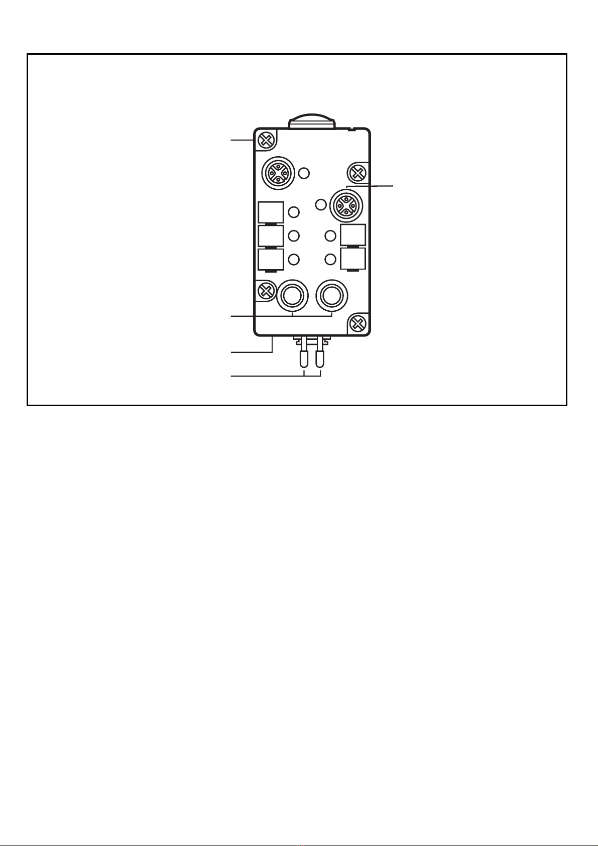
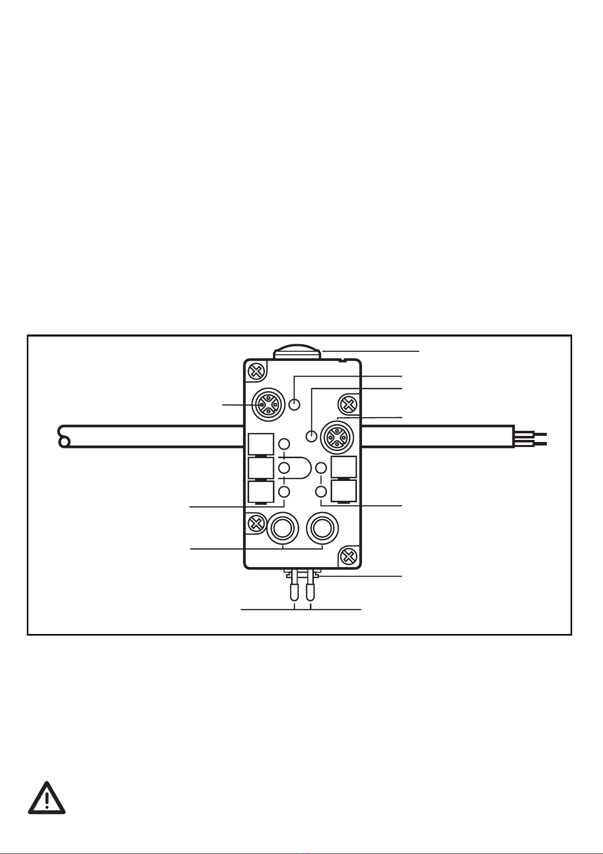
Fonctionnement et caractéristiques
L’Airbox AS-i est un esclave dans le réseau AS-i (profil AS-i S 7.F). Il éta-
blit la communication entre le maître et les deux doubles capteurs et
les deux distributeurs pneumatiques.
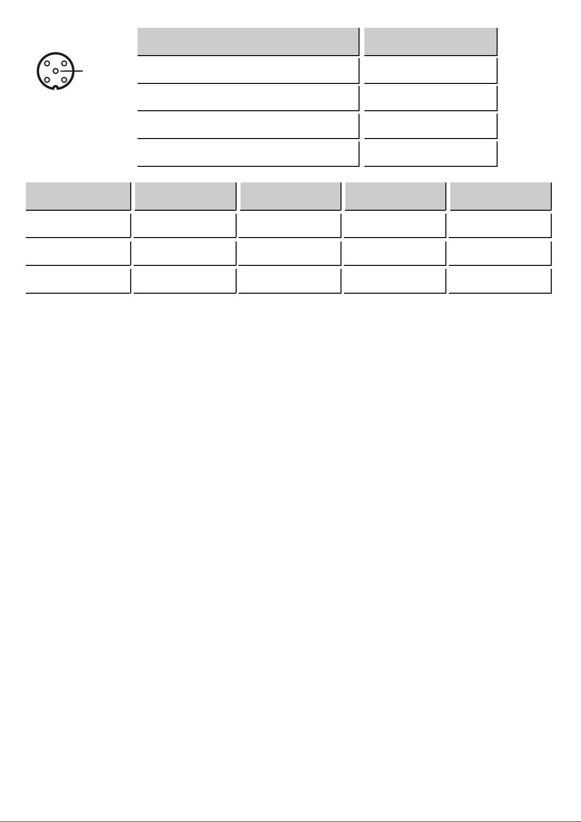
•Alimentation des capteurs intégrée (100mA au total par module)
•Connexion embrochable M12 pour les capteurs
•Raccordement AS-i via le module de câblage EMS
•Raccord pneumatique via le système Legris 3000 /8mm, calibrage
extérieur selon la norme CETOP RP 54 P
•Fonctionnement avec de l'air compriméde 2 à8 bar. (Des pics de
pression >8bar peuvent causer des défauts d'étanchéitépermanents
et des dommages irréversibles àl'AirBox).
•Commande manuelle en appuyant / relâchant ou appuyant /
tournant / verrouillant
Montage
Affectation de l'adresse àl'aide de l'unitéd'adressage.
Monter le module sur l'unitéd'adressage. Affecter une adresse libre
entre 1 et 31; à la livraison l'adresse est 0. Puis monter le module
sur le module de câblage raccordéau réseau AS-i, couple de serrage
0,8Nm.
Dans un environnement poussiéreux l'AirBox peut être monté
avec le filtre vers le bas.
10
I-1/2 I-3/4
I-1
I-3
I-4, O-4
I-2, AS-i PWR, O-3
échappement 3 [R]
air comprimé1 [R]
câble plat AS-i jaune
distributeurs
pneumatiques O-3/O-4
commande manuelle 2
commande manuelle 1
pour O-3

Matières
Air comprimé
Suivre les prescriptions de sécuritéet les règlements pour l’installation
de systèmes pneumatiques. Mettre l’installation hors pression.
Raccorder l’alimentation en air comprimé1 (P), les distributeurs pneu-
matiques (O-3, O-4) et, si nécessaire, l’échappement 3 (R). Il faut cou-
per droit les tuyaux et les pousser dans les raccords jusqu’au déclic.
Déconnexion des tuyaux
Pour enlever les tuyaux appuyer sur l’anneau noir et tirer le tuyau en
même temps.
Commande manuelle
Les commandes manuelles permettent d’activer les distributeurs pneu-
matiques. Si l’on appuie sur la commande manuelle 1, la sortie O-3 est
commutée. Si l’on appuie sur la commande 2, la sortie O-4 est com-
mutée.
11
(1) Viton
(2) acier INOX (303)
(1) joint torique
(2) commande manuelle
(1) joint profilé/ joint plat
(1) joint torique
(2) raccord instantané
avec poussoir
(2) vis de fixation

Compatibilité électromagnétique (CEM):
L'AirBox est conçu pour le fonctionnement dans des environnements
industriels. Le test de décharge électrostatique a étédéterminéselon
EN 61000-4-2 avec les niveaux de test suivants:
•Décharge par contact ±4kV
•décharge par air ±8kV
Des applications spécifiques comme par exemple le transport et la dis-
tribution de matières en vrac peuvent générer des charges électrosta-
tiques plus fortes.
Pour éviter des décharges électrostatiques les remèdes suivants sont
possibles, entre autres:
•compensation de potentiel selon les instructions d'installation
•Pose séparée de
- câbles de signaux et câbles bus
- conducteurs d'équipotentialité
- câbles d'alimentation
•séparation physique de l'AirBox et tous les câbles de toutes parties
chargées électrostatiquement ou dérivant des charges électrosta-
tiques.
Si ces décharges ne sont pas évitées il y a un risque de:
•blessure ou atteinte au personnel d'opération et d'entretien
•formation d'étincelles
•détérioration de l'AirBox
•détérioration de l'équipement électrique
La commande électrique est prioritaire sur la commande manu-
elle.
12

Fonctionnement
Vérifier le bon fonctionnement du module.
•LED verte: alimentation en tension via le réseau AS-i
•LED jaunes: affichage des entrées / sorties
Pour un fonctionnement sans problèmes, de l'air suffisamment traité
doit être utilisé(air filtré5µm, lubrifié(ISO-VG10)1) ou non lubrifié).
Si l'AirBox a étéutiliséune première fois avec de l'air lubrifié, il doit
ensuite toujours être utiliséavec de l'air lubrifié(la lubrification initiale
n'est plus effective dés que l'on a utiliséde l'air lubrifié).
1) Vous trouverez des notes supplémentaires sur l'air compriméet
CEM/ESD pour l'AirBox sur www.ifm-electronic.com. Saisissez le
numéro d'article de votre AirBox sous "Fiche technique" àla page
d'ouverture. Vous recevrez des informations complémentaires sur le
produit en cliquant sur "Information sur produit".
13
1
34
2
n.c.
prise M12 broche
alimentation des capteurs L+ 1
alimentation des capteurs L- 3
entrée de données I 4
entrée de données II 2
bit de données D0 D1 D2 D3
entrées/sorties I-1 I-2 I-3/O-3 I-4/O-4
prise I-1/2 I-1/2 I-3/4 I-3/4
broche 4 2 4 2
Table of contents
Languages:
Other IFM Electronic Cables And Connectors manuals