iFootage Shark Slider Mini Series User manual

INSTRUCTION MANUAL
FOR THE SHARK SLIDER MINI SERIES
DK0801001
Thank you for purchasing this iFootage product, The Shark Slider Mini is compact,
lightweight, easy to carry and is ideal for all types of studio and location camera
movement.
To get the most from your Shark Slider Mini, please read the following instructions
carefully before operating the equipment. Please keep the manual safe for future
reference.
This instruction manual supports the following:
TECHNICAL INFORMATION
FEATURES
PRECAUTIONS
COMPONENT DESCRIPTION
STATE INDICATORS
INSTALLATION GUIDE
SET UP AND SCENARIOS
MAINTENANCE
Whilst every care has been taken to ensure that this manual supports the product and our
customers, some ambiguity or description omissions may exist. We always welcome
customer feedback on how we can improve the product manual.
Contents
Notes: Please read the following information:
Please note that customers who have purchased the following will need to download the
iFootage App which currently supports iPhone IOS8.3 and above and will soon support
iPad and Android: Mini 2 Axis Module, Mini 3 Axis Module, Shark Slider Mini Complete and
Shark Slider Mini Premium.
Please check all components and packaging for any damage. In the case of missing or
defective parts, please contact your distributor as soon as possible.
When the motion module is switched off but still connected to power via a USB port, power
will still be supplied to the battery. When the motion module is switched on, power is supplied
directly to the motion module. If the battery inside the motion module is in power off mode the
battery will not charge .
1.Shark Slider Mini Track
2.Shark Slider Mini Standard
3.Shark Slider Mini Bundle
4.Mini 2 Axis Module
5.Mini 3 Axis Module
6.Shark Slider Mini Complete
7.Shark Slider Mini Premium

Technical Information
Shark Slider Mini Track Length
Track SpecificationsWeight
Material Aluminum magnesium alloys + SUS304 Stainless steel
Shark Slider Mini Standard Length
Useable Length
Weight
Material
Max load
with pulley
Shark Slider Mini Bundle
Track Specifications
Weight
Material
Track Specifications
Length
Max load
Mini 3 Axis Module
Module slider
Location accuracy of Module
Load of Slider tilt 45°
Slider motor power
Slider endurance time
Radio frequency Bluetooth and 2.4GHz
Operating voltage
Spin speed
Location accuracy of Pan Head
Max Load of Pan Head
Pan Head motor power
Pan Head endurance time
Pan Head self-weight
Radio Signal Range
Battery model
0.68Kg/1.5Lb
2.2Kg(with pulley)/4.85Lb
Aluminum magnesium alloys + SUS304 Stainless steel
Aluminum magnesium alloys + SUS304 Stainless steel
Useable Length

1.
.
3.
4.
8.
13.
14.
Features (depending on package purchased)
Lightweight, compact, portable and easy to deploy.
Seamless track locking design with track extensions available as an accessory.
High quality design, engineering, durable materials (hard anodized technology)
and components.
Unique, quick release, original design flywheel and motion module.
Agile and adjustable angle of carriage plate, allows for fast adjustment of camera
position.
Modular design allows for future additions and updates to mini slider including
moving from manual operation to automated motion control of up to 3 axis.
Highest location accuracy for motion control slider is 0.00325mm and for the Pan
and Tilt Head it is 0.001°.
Starting point detection avoids repetition of manual reset with multiple recordings.
USB power charge and power supply to motors.
Reliable, wireless control using Bluetooth BLE 4.0 and 2.4 GHz.
Instant automatic connectivity via Smartphone Bluetooth BLE 4.0.
Multiple key frame Bezier curve preset timeline function allowing you to accurately
programme all three axis. Perfect for sophisticated time-lapse recording.
iFootage motion control App with free firmware updates.
The Shark Slider Mini connects via Bluetooth BLE 4.0 technology. Prior to opening
App ensure that your Smartphone's Bluetooth is activated.
Please use only FW50 batteries. Alternative batteries may damage the unit.
As a result of lithium battery discharge characteristics and the overall power
requirement for the Shark Slider Mini to operate, should the battery power be 10%
or less, the operation time may be reduced to less than 10 minutes. Please ensure
that batteries are fully charged so that there is sufficient power for sustained
operation.
Once activated, Motion X2 automatically moves to the initial status/zero point.
Please ensure that the track is clear of obstacles prior to starting. It is recommended
that users keep their hands clear of the tracks also to avoid damage or injury.
Always protect the equipment when working in dusty, damp or wet environments.
Failure to ensure adequate protection from elements may result in equipment failure.
Do not use this motion control unit in environments above 50°C and below-20°C
degrees.
Precautions
Any disassembly or modification without authorization or improper use of the equipment
may result in damage and affect the warranty.
Automatic target control (focal point detection)-ideal for interviews.
Preset, repeatable camera movement.
Slider can be utilized both vertically and horizontally.
Panoramic function.
Photostitching function.
Toolless and beltless assembly for super smooth movement.
5.
6.
7.
9.
10.
11.
12.
15.
16.
17.
18.
19.
1.
3.
4.
5.
6.
7.
2.
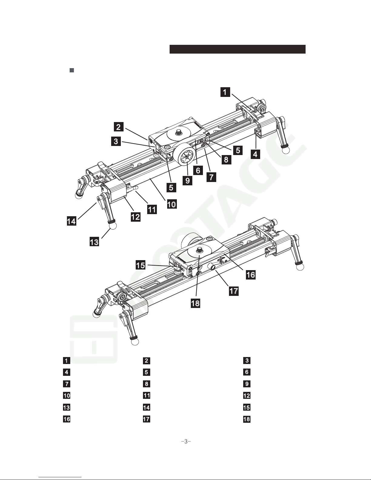
Component description
Shark Slider Mini Standard
Foot stand lock buckle 1/4'' hole Angle plate buckle
Clamp-A Lock buckle of 1-Axis module Carriage
Flat pulley Carriage locking control Flywheel
Track Clamp-B Foot stand
Adjustable legs Locking control Hanging buckle
Angle plate Angle locking control 3/8'' screw

864
53 2 1
8
12
7
5
4
9
10
11
LED1 LED2 LED3 LED4
LED1
LED2
LED3
LED4
7
7
Shark Slider Mini Motion Control Version
Hanging pulley Battery cable cover Battery cover
Micro USB port 2.5 inch shutter interface Slider module
Indicator light Power switch Locking button for X2 Mini
1/4'' screw 1/4'' Screw / 3/8'' Screw Locking control
*Micro USB port supplies power to Pan and Tilt Head and Slider or can be used
to charge battery.
*To reset to factory settings, press and hold the On/Off switch, then insert the
battery and wait 10 seconds until the red light flashes to indicate the reset is
complete.
Component description
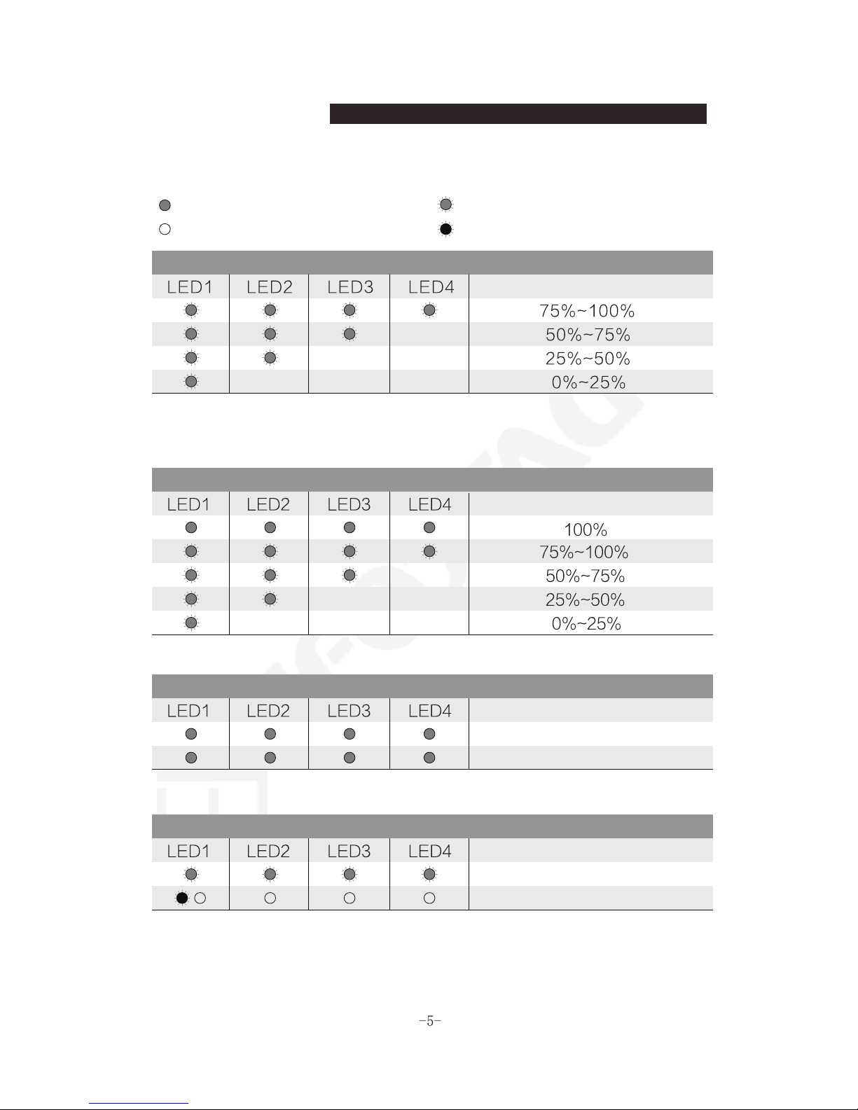
Status indicators
LED status explained:
LED green LED flashes green
LED off LED flashes red
Battery level
Current battery level
* Quick press the On/Off switch to check the battery level while the unit is
powered off.In standby mode the LED will flash every two seconds to indicate
the battery level.
Battery charging level
* Insert 5V USB to charge the unit during powered off mode.
Shutter status
Current state
Shutter ready to fire
Shutter fire after 0.3s
On/Off status
Current state
LED flashes from 1 to 4 and all 4 LED flash 3 times.
* To switch ON or Off, press and hold the On/Off switch for 2 seconds.
Current battery level
LED lights off from 4 to 1 and all 4 LED red lights flash 4 times.
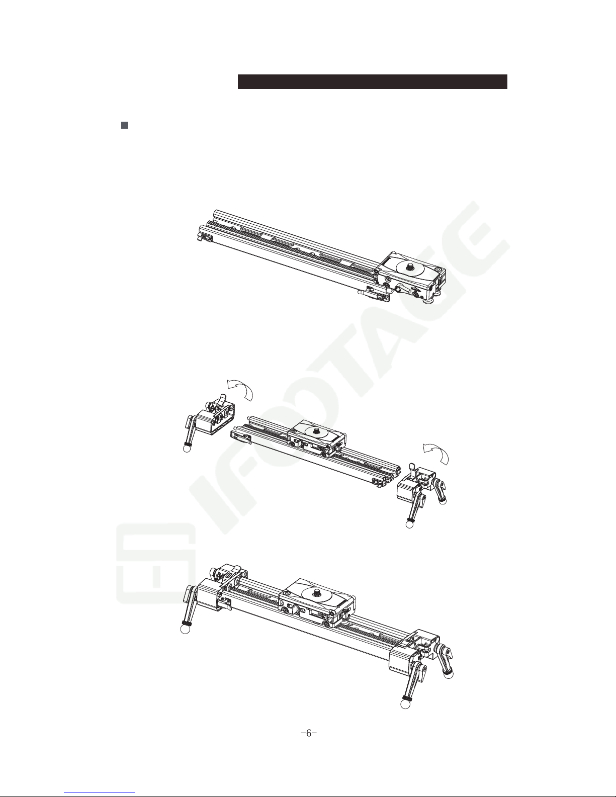
Installation guide
How to install the carriage
Step 1: Attach carriage by carefully sliding carriage onto the track at one end.
Gently push carriage along length of track to ensure correct contact
and smooth operation.
Step 2: Attach both track end/feet by opening buckle connection on track, pushing
into place and locking using buckle system. You may wish to attach one end
prior to attaching carriage, then fit the other end.
Completed installed diagram for reference:

How to install the flywheel
Step : Press the flywheel into the receiving port on the side of the carriage.
You will audibly hear it click as it locks into place. Move carriage or turn
flywheel to check it is installed correctly.
Completed installed diagram for reference:
Installation guide
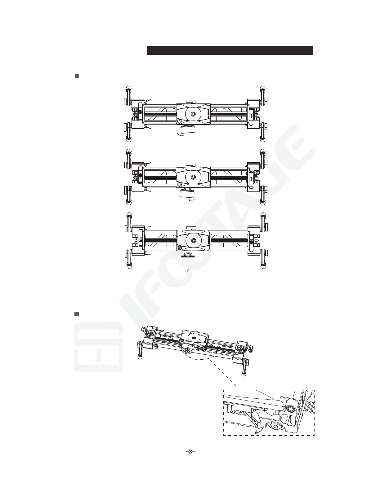
How to remove the flywheel
Firmly hold the flywheel and gently pull to the left, then do the same, but to the
right followed by pulling the flywheel away from the carriage at 90 degrees. This
will ensure safe removal of the flywheel from the carriage.
Locking the module
In order to prevent the carriage from moving,
rotate the carriage locking control, following
the direction of the arrow direction.
(Note: Locking is not intended to lock the unit
completely in position, it is designed to assist
stability during 2 axis operation with the X2 Mini)
Installation guide

Mounting the Shark Slider Mini onto a tripod with a hemisphere base
Step 1: Attach the hemisphere base onto the slider using the central screw
hole on the track underside. Screw the hemisphere base in a clockwise
direction until fully tightened.
Hemisphere base
Step 2: Mount the hemisphere base on the tripod and adjust the slider until the
carriage's spirit level shows the slider is horizontal, Lock into position.
Spirit level
Bowl
Locking handle
Installation guide
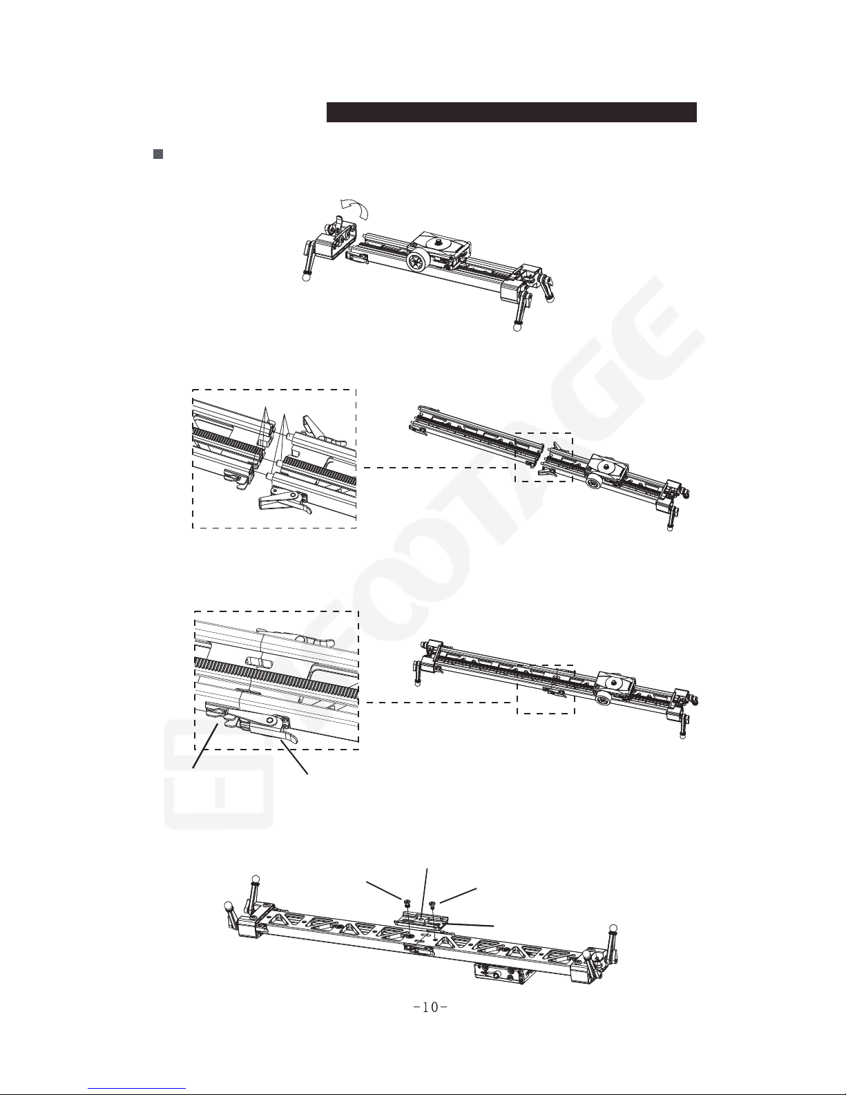
Extending the track
Step 1:Remove the foot stand from one end of the slider.
Step 2: Attach the track extension to existing track using the male and female
connecting nodes. (see diagram).
Step 3: Use the buckle locking system to lock the two tracks together. Check
buckles are closed and tracks are secured together successfully prior to
replacing and locking in place the foot stand.
Joint-A(female track)
Joint-B(male track)
Clamp-A(Female lock) Clamp-B(Male lock)
Step 4: Place the track connection plate on the underside of the joined track and
secure with screws provided. Check that the plate is secure and is adequately
supporting the track joint.
3/8 ''hole
3/8'' screw 1/4''screw
Connection plate
Installation guide
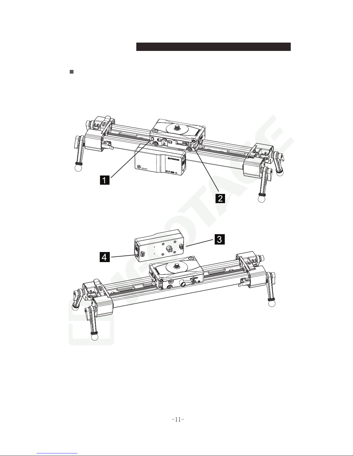
How to install the single-axis module
Installation guide
Step 1:Remove the flywheel as per instructions.
Step 2:Attach the single-axis module onto the carriage as shown in the figure.
Step 3:Check that the single-axis module is securely attached to the carriage.
Step 4:Check track is clear of obstruction.
Step 5:install battery and switch on unit.

How to install the battery
Step :To open up the battery cover move the switch to 'OPEN'.
Battery Type: FW50
Battery curved side
*Insert the battery in the 1 -axis module, pay attention to the direction,
DO NOT insert it in opposite direction.
Installation guide
Step 2:Carefully install battery ensuring positive
end is connected correctly.
Step 3:Close battery compartment
Battery curved side
Automatic starting point function
Step :Insert the battery and close the battery cover. Press and hold “On”
switch for at least two seconds until the four indicator lights flash three
times (green light), after which the pan head will begin to move to the
direction as shown in the chart.
*The carriage will stop automatically 10mm from the left foot stand.(The 1 axis
slide module is equipped with a sensor which will move to the starting point
and stop automatically)
*For maximum run time, please ensure that you run the single axis module on
a fully charged battery.
Installation guide
Automatic Sensor
Automatic Sensor
Automatic Sensor
Automatic Sensor

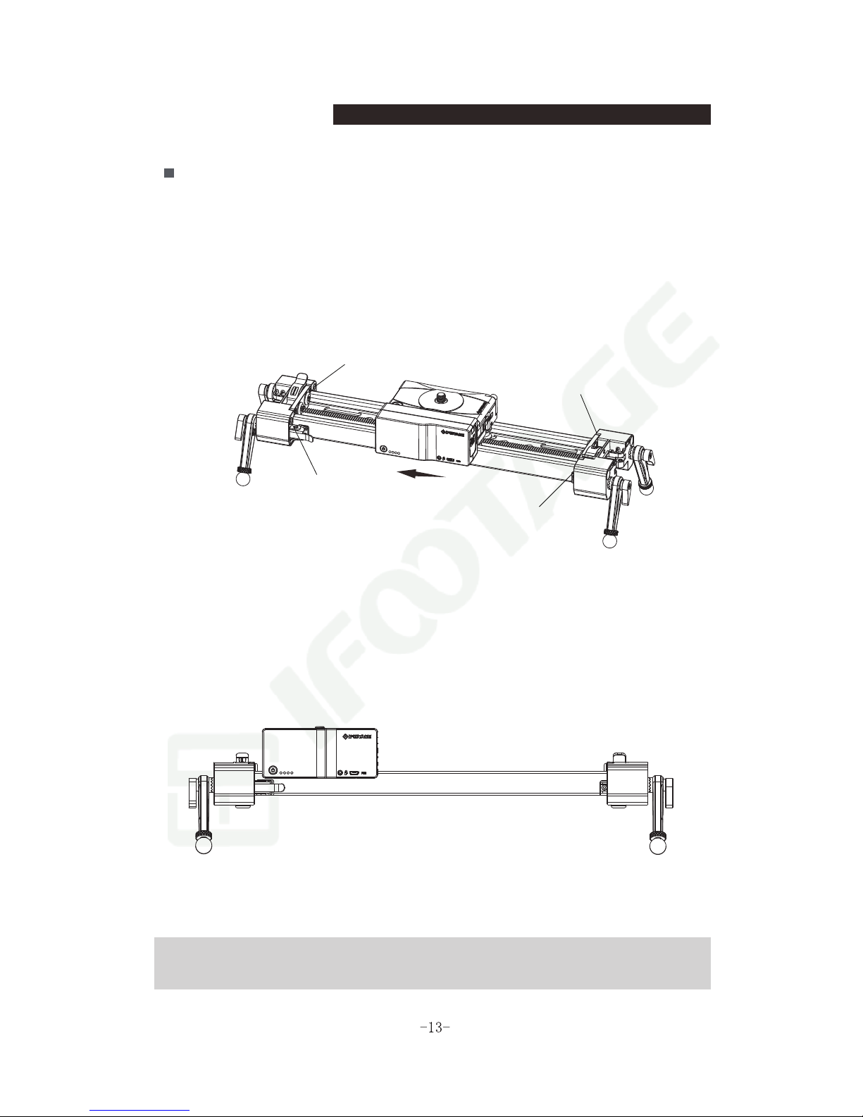
How to disassemble the single axis module
Step 1:Press the locking latches on both sides of the unit simultaneously.
Step 2:Gently remove the single axis module from the carriage at a 90 degree
angle to the carriage.
Installation guide

Carriage Angle Plate
Step :Turn the angle plate anti-clockwise. Press to release the angle plate latch,
lift the angle plate and adjust to desired angle.
Spirit Level
Angle Plate
Angle plate latch
Angle Plate Lock
How to use the loading function
Step 1:Install the pulley cord (Push the pulley pins through the groove at the end).
Pulley Mounting Groove
Pulley Pin Installation Diagram
*The carriage and camera may slip if the rake or slider set up angle is too
steep. This can be prevented by using the pulley and correct counterweight.
These should be removed when not in use.
Installation guide

How to use the loading function
Step 2:Attach the counterweight and secure the cord to the hanging buckle.
Step 3:Set up fully loaded slider at the angle you wish to use it and carefully
test out counterweight. Increase or reduce weight accordingly.The
pulley must be installed using an appropriate counterweight for the
set up and weight of the camera and head.
*Care must be taken to ensure that user's fingers and hands are not 'pinched'
or trapped within moving the parts.
Installation guide

Using the remote control App
How to mount the X2 Mini on a tripod
3/8'' screw
3/8'' thread hole
Rotate
to mount
Rotate
to mount
Step 1:Please ensure that the tripod camera plate has a 3/8'' screw and therefore
matches the X2 mini pan head 3/8'' screw thread.
Step 2:Carefully place the X2 Mini onto the tripod camera plate and screw the two
together ensuring the thread is not crossed.
Step 3:Tighten and lock plate onto tripod.
Step 4:Check items are secure prior to use.Carry out reverse procedure when
removing X2 Mini from a tripod.

Installing the X2 mini onto the shark slider mini
3/8'' screw 3/8'' thread hole
Using the remote control App
Step 1:Carefully place the thread 3/8'' hole of the X2 Mini pan head onto the 3/8''
screw on top of the Shark Slider carriage. Rotate clockwise.
Step 2:Press the pan locking button and rotate the pan head at the same time to
lock the pan head tighter. You will also need to press the locking button
when removing the pan head from the slider carriage.
Step 3:Please mount the camera as shown in the diagram when using the target
control feature.
Rotate
to mount
Rotate
to mount
This manual suits for next models
7


