IFR Systems FM/AM-1200S/A User manual

OPERATION
MANUAL
FM/AM- 1200S/A
COMMUNICATIONS
SERVICE
MONITOR
10200 West
York
Street/Wlchita,KS 67215 U.S.A./(316) 522-4981/TWX 910-741-6952

PUBLISHED BY
IFR SYSTEMS, INC.
Wichita, Kansas
COPYRIGHT
0
1988
by
IFR
SYSTEMS, INC.
All
rights reserved. Printed in the United States of America. No part
of this publication may be reproduced, stored in a retrieval system, or
transmitted in any form or by any means, electronic, mechanical, photo-
copying, recording or otherwise without the prior permission of the
publisher.
i
Manual Part Number: 1002-5501-000

WARNING:
HlGH VOLTAGE EQUIPMENT
THlS EQUIPMENT CONTAINS CERTAIN CIRCUITS AND/OR COMPONENTS OF
EXTREMELY HlGH VOLTAGE POTENTIALS, CAPABLE OF CAUSING SERIOUS
BODILY INJURY OR DEATH. WHEN PERFORMING ANY OF THE PROCEDURES
CONTAINED IN THlS MANUAL, HEED ALL APPLICABLE SAFETY PRECAUTIONS.
RESCUE OF SHOCK VICTIMS
1.
DO NOT ATTEMPT TO PULL OR GRAB THE VlCTlM
2.
IF POSSIBLE, TURN OFF THE ELECTRICAL POWER.
3.
IF YOU CANNOT TURN OFF ELECTRICAL POWER. PUSH, PULL OR LIFT
THE VlCTlM TO SAFETY USING A WOODEN POLE, A ROPE OR SOME
OTHER DRY INSULATING MATERIAL.
FIRST
AID
1.
AS SOON AS VlCTlM IS FREE OF CONTACT WITH SOURCE OF
ELECTRICAL SHOCK, MOVE VlCTlM A SHORT DISTANCE AWAY FROM
SHOCK HAZARD.
2.
SEND FOR DOCTOR AND/OR AMBULANCE.
3.
KEEP VlCTlM WARM. QUIET AND FLAT ON HISIHER BACK.
4.
IF BREATHING HAS STOPPED
,
ADMINISTER ARTIFICIAL
RESUSCITATION. STOP ALL SERIOUS BLEEDING.

[c-1
INTEGRATED CIRCUITS AND SOLID STATE DEVICES SUCH
AS MOS FET'S, ESPECIALLY CMOS TYPES, ARE SUS-
CEPTIBLE TO DAMAGE BY ELECTROSTATIC DISCHARGES
RECEIVED FROM IMPROPER HANDLING, THE USE OF
UNGROUNDED TOOLS, AND IMPROPER STORAGE AND
PACKAGING. ANY MAINTENANCE TO THIS UNIT MUST
BE PERFORMED WITH THE FOLLOWING PRECAUTIONS:
1.
BEFORE USING IN A CIRCUIT, KEEP ALL LEADS
SHORTED TOGETHER EITHER BY THE USE OF
VENDOR-SUPPLIED SHORTING SPRINGS OR BY
INSERTING LEADS INTO A CONDUCTIVE MATERIAL.
2.
WHEN REMOVING DEVICES FROM THEIR CONTAINERS,
GROUND THE HAND BEING USED WITH A CONDUC-
TIVE WRISTBAND.
3.
TIPS OF SOLDERING IRONS AND/OR ANY TOOLS
USED FUST BE GROUNDED.
4.
DEVICES MUST NEVER BE INSERTED INTO NOR
REMOVED FROM CIRCUITS WITH POWER ON.
5.
PC BOARD, WHEN TAKEN OUT OF THE SET, MUST
BE LAID ON A GROUNDED CONDUCTIVE MAT OR
STORED IN A CONDUCTIVE STORAGE BAG.
Remove
any
built-in power source, such
as a battery, before
laying
PC Boards
on conductive mat or storing
in
con-
ducti
ve bag.
6.
PC BOARDS, IF BEING SHIPPED TO THE FACTORY
FOR REPAIR, MUST BE PACKAGED IN A CONDUC-
TIVE BAG AND PLACED IN
A
WELL-CUSHIONED
SHIPPING BOX.

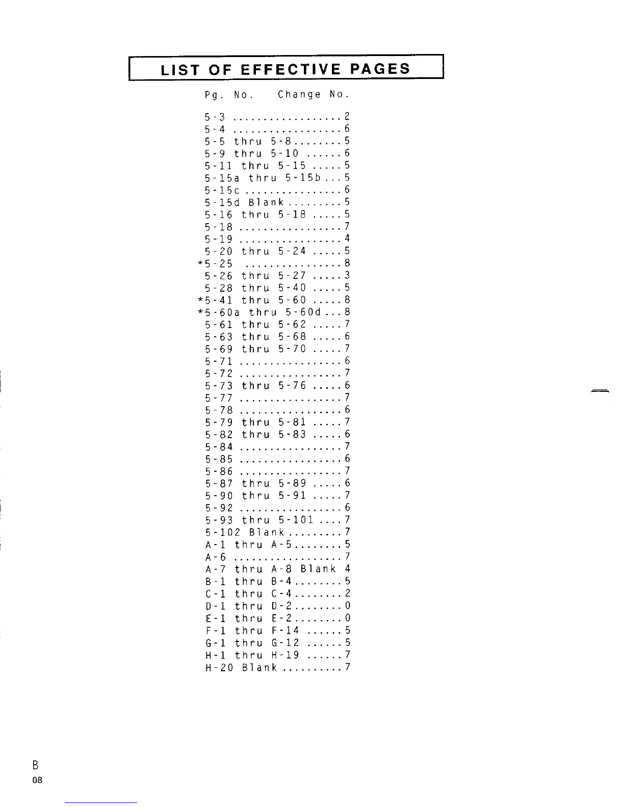
LIST OF EFFECTIVE PAGES
I
The manual pages listed below are identified by
revision number
.
Those pages affected by the
current change or revision are so identified
by
the
current revision number and an asterisk
(*)
.
.......
Original
.......
0
March
1.
1986
.......
.......
Revision
1
September
22. 1986
.......
.
Revision
.......
2
June
22 1987
....... .......
Revision
3
September
15. 1987
.......
Revision
.......
4
April
15. 1988
.
Revision
.......
5
.......
November
1
1988
Revision
.......
6
.......
November
15. 1989
.......
.
Revision
.......
7
April
17 1990
.
Revision
.......
8
.......
September
1
1991
TOTAL NUMBER OF PAGES IN THIS MANUAL IS
288:
CONSISTING OF THE FOLLOWING:
Pg
.
No
.
Change No
.
Title Page
..........
0
Copyright Page
.....
4
Warning Page
.......
0
Caution Page
.......
0
*A
....................
8
*B
....................
8
i
....................
0
ii
...................
2
iii
thru xii
.......
6
1-1
thru
1-3
.......
5
1-4
Blank
...........
2
2-1
..................
2
2-2
thru
2-4
.......
5
2-5
..................
2
2-6
..................
5
3-1
Blank
...........
0
3-2
..................
5
3-3
..................
6
3-4
..................
0
3-5
thru
3-7
.......
4
3-8
..................
0
3-9
..................
2
3-10
.................
0
3-11
.................
3
3-12
.................
5
3-13
.................
2
3-14
.................
5
4-1
..................
5
4-7
..................
0
Pg
.
No
.
Change No
.
4-8
thru
4-11
.....
2
4-12
................
3
4-13
thru
4-14
....
2
4-15
................
0
4-16
................
2
4-17
thru
4-17a
..
5
4-17b
Blank
.......
2
4-18
................
2
4-19
thru
4-21
....
0
4-22
thru
4-24a
..
2
4-24b
Blank
.......
2
4-25
................
2
4-26
................
0
4-27
thru
4-29
....
2
4-30
................
6
4-31
thru
4-33
....
5
4-34
thru
4-35
....
2
....
4-36
thru
4-39 5
4-40
................
6
4-41
................
4
4-42
thru
4-43
....
2
4-43a
thru
4-43c
.
5
4-43d
..............
2
4-44
................
2
4-45
thru
4-46
....
5
4-47
thru
4-48
....
2
4-49
thru
4-50
....
5
4-51
thru
4-52
....
2
5-1
thru
5-2
......
4
LIST
OF
EFFECTIVE
PAGES
Pg
.
No
.
Change
No
.
5-3
..................
2
5-4
..................
6
........
5-5
thru
5-8 5
......
5-9
thru
5-10 6
.....
5-11
thru
5-15 5
...
5-15a
thru
5-15b 5
................
5-15c 6
5-15d Blank
.........
5
.....
5-16
thru
5-18 5
5-18
.................
7
5-19
.................
4
.....
5-20
thru
5-24 5
................
*5-25 8
.....
5-26
thru
5-27 3
.....
5-28
thru
5-40 5
*5-41
thru
5-60
.....
8
...
*5-60a
thru
5-60d 8
.....
5-61
thru
5-62 7
.....
5-63
thru
5-68 6
.....
5-69
thru
5-70 7
.................
5-71 6
5-72
.................
7
.....
5-73
thru
5-76 6
5-77
.................
7
.................
5-78 6
.....
5-79
thru
5-81 7
.....
5-82
thru
5-83 6
5-84
.................
7
.................
5-85 6
5-86
.................
7
.....
5-87
thru
5-89 6
.....
5-90
thru
5-91 7
.................
5-92 6
....
5-93
thru
5-101 7
5-102 Blank
.........
7
........
A-1
thru
A-5
5
A-6
..................
7
A-7
thru
A-8 Blank 4
........
B-1
thru
8-4 5
........
C-1
thru
C-4 2
........
D-1
thru
D-2 0
........
E-1
thru
E-2 0
......
F-l
thru
F-14 5
......
G-1
thru
G-12 5
......
H-1
thru
H-19 7
..........
H-20 Blank 7

PREFACE
SCOPE
This manual contains instructions for operating the FMIAM-1200S/A
Communications Service Monitor. The instruction level of this manual is
relatively basic and presupposes no previous experience'on the part of
the operator with a communication service monitor of this type.
A
basic
understanding, however, of communication electronics and practical
troubleshooting methods
will
be helpful.
It
is strongly recommended
that operator be thoroughly familiar with Sections
1
through 3 of this
manual before attempting to perform any operating procedures contained
in Section
4.
APPLICABILITY
All
information contained in this manual a~~liesto both the FMIAM-1200s
and FM/AM-1200A models, except where otherwise noted. For reasons of
brevity, whenever text ifiormation is applicable to both models, the
units are referenced as OIFM/AM-1200S/A1' (instead of FMIAM-1200s and
FM/AM-1200A separate1y).
ORGANIZATION
The operation manual is divided into the following major sections:
SECTION
1
-
INTRODUCTION
Provides a brief introduction to the FM/AM-1200S/A including pur-
pose, functional capabilities and uses.
SECTION 2
-
INSTALLATION
Provides a step-by-step procedure for setting up the FMIAM-
1200S/A for operation.
SECTION
3
-
DESCRIPTION OF CONTROLS, CONNECTORS
&
INDICATORS
Identifies and functionally describes all FM/AM-1200S/A controls,
connectors and indicators.
As an operating aid, Figure 3-1 (which locates
and identifies all FM/AM-1200S/A front panel
controls) has been incorporated into a fold-out
page. By extending the fold-out page, the
operator can easi
1
y
reference any front panel
control while simultaneously performing any
operating procedure contained elsewhere in this
manual.
SECTION
4
-
OPERATION
.....................
Contains instructions for operating the FM/AM-1200S/A Keyboard
and VFD. Using the Keyboard, the operator can enter data into
the FM/AM-1200S/A in the following modes:
1.
Direct Data Entry
2.
Programmed Data Entry into Memory
3.
Executed Data Entry from Memory
In addition to Keyboard operation, this section contains a selection of
basic operating procedures pertaining to all major functions of the
FM/AM- 1200S/A.
SECTION
5
-
AVAILABLE OPTIONS
Contains descriptions and operating procedures of available
options to the FM/AM- 1200S/A.
Useful supplementary information relating to the operation of the
FM/AM- 1200SJA is contained in appendices at the rear of the manual
.
(See Table of Contents for a detailed 1ist of manual contents.)

TABLE OF CONTENTS
List
cf
Effective Pages
......................................................
A
Prefare
........................................................................
i
.
.
List
of I~iustrations
........................................................
ix
SECTION
1
.
INTRODUCTION
Paragraph Title Page
1-1
General
........................................................
1-1
1-7
Signal Generator/Recei ver
..................................
1-1
1-3 FMiAM-1200SIA Capabi
1
i
ties
.................................
1-2
1-4 Data Display
and
Control Features
.........................
1-3
.......................
1
.
5
GeneratorIReceiver Support Function 1-3
1-6 Available Options
............................................
1-3
SECTION
2
.
INSTALLATION
2-1 General
.......................................................
2-1
2
.
2
Precautions
...................................................
2-1
?
.
-2
...................................................
L
..
Preparation 2-2
-
2
.
4
General Operating Data
......................................
2.5
2
5
External Power Interruption Protection
...................
2-6
SECTION
3
.
DESCRIPTIONOF CONTROLS. CONNECTORSAND INDICATORS
7.1
FMIAM-1200S/A Front Panel
...................................
3-2
3
.
2
FMiAM-1200SIA Rear Panel
....................................
3-11
?.
.
3 Keyboard and
VFD
Description
...............................
3-12
3-2-1 Function Keys
.................................................
3.13
3-1-2 Instruction Keys
.............................................
3-14
3.3.3 Cursor Control
Keys
..........................................
3.14
3-3-4 Data Entry Keys
...............................................
3-14
SECTION
4
.
OPERATION
General
.......................................................
4-1
..............
Mini-Index of Content:
hi
thin this Section 4.1
Direct Dzta e!itry
............................................
4-2
Direct RF Data Entry
.........................................
4-2

Paragraph
4-2-2 Title Page
Direct TONE Entry
............................................
4.2
Direct DTMF and IMTS Entries
...............................
4-4
Direct OFFSET Entry
..........................................
4-6
................................................
Meter Function 4-6
Set Intensity (VFD)
..........................................
4-7
Programmed Data Entry into Memory
.........................
4-8
.........................................
Programmed RF Memory 4-8
Programmed TONE Memory
......................................
4.10
Programmed DTMS and IMTS Memory
...........................
4.12
Programmed OFFSET Memory
....................................
4.13
Programmed DCS Memory
.......................................
4-14
Programmed T SEQ Memory
..................................... 4.
15
Programmed Two Tone Memory Sequence
.......................
4-17
Programmed SCAN Memory
......................................
4.18
......................................
Programmed STEP Memory
4-19
-
-
Executed Data Entry
..........................................
4-21
Executing RF Functions
......................................
4-21
....................................
Executing TONE Functions 4-21
Executing DTMSIIMTS (PULSE) Functions
....................
4-22
Executing OFFSET Function
...................................
4.22
Executing SCAN Function
.....................................
4-23
Executing DCS Function
......................................
4-23
Executing T SEQ Function
....................................
4.24a
Executing STEP (RF
&
TONE) Function
.......................
4-25
Executing Variable IMTS Audio Function
...................
4-27
Receiver Operation
...........................................
4.28
General
........................................................
4-29
Basic Receiver Operation
....................................
4.30
Receiving AM or FM Signals (Off-the-Air)
.................
4-31
Receiving SSB Signals (Off-the-Air)
.......................
4-31
Testing AM or FM Transmitters
..............................
4-32
Measuring AM of FM Transmitter Distortion
...............
4.32
Title Page
RF
Siqnal Gtrier,itor Operation (Simplex)
..................
4.34
..
r
General
........................................................
4-23
Signal Generdtor Operatiori (Simplex)
.....................
4.36
Generating AM or
FM
Modulated RF Signals
.................
4-?5
Externally Modulatina RF Signal Generatsr
...............
4-38
Voice Modulatirig
RF
Signal Generator
.....................
3-38
............................................
Variable Generate 4.39
Measuring UUT Receiv~rSINAD Sensitivity
.................
4-3c
Duplex Operation
.............................................
4-40
General
........................................................
4-41
Duplex Testing Using Sepurate TransmitiReceive Lines
(Ful1 Duplex Operation) (FM:AM-1LOOA Only)
..............
4-41
Off-the-Air Duplex Testing (FMIAM-1200A Only)
...........
4-42
Duplex Testing Using Common TransmitlReceive Line
(Half-Duplex Operation (FMIAM-1200 A Only)
.............
4.42
Duplex Testing
(
FMIAM-1200A On1y)
.........................
3.42
Duplex Generate Mode (FMIAM-1200A 0111
y
I
..................
4-43
Selecting "Duplex High" or "Duplex Low"
(FMIAM-1200s Only)
...........................................
4.43a
Duplex Testing Methods
(
FMIAM-1200s Only)
...............
4.43a
Duplex Test (FM/AM-1200s Only)
.............................
4-43c
Duplex Getierate I4ode
(
FMIAM-1LOOS On1
y
..................
4
.-l
2.d
......................................
Oscilioscope Operation 4.44
........................................................
General 4-45
External Oscil
lilscope Operation
...........................
4.45
Internal Oscilloscope Operation
...........................
4.45
..........................................
Residual Distortiori 4-45
Tone Generator
................................................
4.46
Spectrum Aiia1:~ii.r Oper,iti'>n FIlII-12Oily
.........
4-47
General
........................................................
4-47
Spectruni Atia1:izer Operatio11
................................
4-49
Tone Generator Optraticn
....................................
4.49
Basic RS-232 Operatiot-i
......................................
4.50
Title Paqe
FM/AM-l2ilOS/A Itlitialization
...............................
4-50
RS.2.32 Coinmalid Procedure and Data Structure
.............
4-51
..........................
A1 lowabl
i
KS-232 Command Formats
45:
......................................
RS-232 Rem~teCommands 4-53
SECTION
5
.
AVAILABLE
OPTIONS
General
........................................................
5-1
.
2
PPM
Frequency Standard
.
Option 01
....................
51
.
05 PPM Frequency Standard
.
Option 02
...................
51
..........................................
Battery
.
Option 04 5.1
.............................
Generate Anrpl ifier
-
Option 05 5-2
General
........................................................
5-2
Installation
................
:
.................................
5-2
......................................................
Operation 5-3
......................................
Microphone
.
Option
06
5-3
Telescoping Antenna
.
Option 07
...........................
5-3
.
Soft Paddsd Carrying Case
.
Option
09
....................
5-3
Digital Voltmeter and DTMF Decoder
.
Option 10
.........
5-4
........................................................
General 5-4
................................
Diqital Voltmeter Operdtion 5-4
ETtlF
['e;(~.ler Uperaticin
......................................
5-6
.........
Europeati Signaling (EncodeiDecode!
.
Option
11
5-2
r
rn
General
........................................................
3-0
Five-Pigit Signaling Formdt Operation (Includes
CCIR
.
EEA.
EIA.
Z'iiEI1.
ZVEI2. ZVEIS. NATEL and EIJRO)
..........
5-8
Programmitig
dnd
Executing ZVEI2 in Generdte Mode
.......
5-9
......................................
Executing Repeat Tones 5-10
Erecutirnq Five Digit Fc,rmat
i
t-I
Receive Mode
............
:5
-11
E.t;util~.
j
lllTEL
in Receive I.liide wit11 PF Set t'z
..................................................
122
.
4567
IklH:
5-12
&
1-
5
.
1
:'.
.I.,
Tolic Sigt~alir~qFgrmat Operation
.......................
Ent~arlzedE~ircpealiSiglialirig (Enco.rie/Dii.odt 1.Optioli
11
w/s':ft;~dr-l Versiot-I 4.0.04 (or Higher) Instal1ed
........
5-l5a

Pra2gramming Eight-Digit Signaling Fcrmat Operaticn
iinclud;; CCIR
.
EEA. EIA. LVEI1. ZVEIZ. ZVEI3. NATEL
....................................
.
EIIRO
CCIRH. and CCIRH4
j
5-150
Entlar~ctd5/15 Tolit. Format
....................................
5-l5b
.........................................
Deviation Set Select 5-15c
"G" Ch~iracterPrograinming
...................................
5-l5c
......
Tracking Generator
.
Option 12
i
FMIAM-1200s Only) 5-16
General
........................................................
5-16
Selecting Tracking Generator Mode of Operation
.........
5-17
Track Adjust
..................................................
5-19
.................................
Vari
;lbl
e Sweep Speed
A
RS-232 Cijmmands for Trackinq Generator
...................
5-20
GPIB Operation
.
Option 13
.................................
5-21
General
........................................................
5-21
Preparation for Using GPIB
.................................
5-21
...............................
FMIAM-1200SIA Initialization 5.21
Remote Control (GPIB) Operati011
...........................
5-22
FMIAM-1200SIA and GPIB Message Interface Definitions
..
5.24
GPIB Transactions
............................................
5-25
..............
ASCII Output Commands to the FMIAM-1200SIA 5-25
ASiii Outpiit Coiillildr~d Ddta iuimat
..........................
526
Retccrn Data Format
...........................................
5-26
Reply Idsiitifier
.............................................
5-27
A1
1
owable GPIB Cominand Formats
.............................
5-27
.........................................
GPIB Remote Commands 5-25
..................
Trunking
-
Option 14 (FMIAM-1200s On1
y)
5-41
General
........................................................
5-41
Trlrlikiii.
2
Opsrational Th;ory
................................
5-41
..............................
Accessirig th? Trunking S.y;%em 5.42
Trunking System Setup Procedure
...........................
548
T~rni.i11g 5:i;teti Test PI-ccttS!rr-t
.............................
5.44
Simple
Enc.
?de!Sir~ple Dscodt t.lod~sand Repeater
....................................................
Access Test 5-50

Paragraph
5-13-7 Title Page
....................................
Repeater Simulation Mode 5-55
Mobile Unit Simulation Mode
................................
5-58
CELLULAR TESTING
AMPS: OPTION 15 (FMIAM-1200s ONLY)
ETACS: OPTION 16 (FMIAM-1200s ONLY
)
...................
5-61
GENERAL
........................................................
5-61
INITIAL SETUP
.................................................
5-62
Manual Mobile-to-Cell Call
.................................
5.68
Meter Displays During Cellular Testing
...................
5-73
...................
Manual Cel 1ular Test SINAD Measurement 5-74
Check DTMF Digits During Manual Cellular Test
...........
5-75
Flash Hook Test
...............................................
5-76
Check Voice Deviation During Manual Cellular Test
......
5-76
Terminating Manual Cellular Test
..........................
5-77
.......
Manual Cell-to-Mobile Call and Auto Handoff Test 5-77
Supervisory Audio Tone (SAT) Measurement
.................
5.81
-
Signal Tone Measurement
.....................................
5-84
Manual UUT Registration
.....................................
5-85
No-Coax Mobile-to-Cell
Call
................................
5.87
No-Coax Cel1-to-Mobi1e Cal1
................................
5.89
Cel1ular Auto Test Procedure
...............................
5-90
Error Messages
................................................
5.96
..........................................
Test Results Review 5-97
RS-232 Remote Cellular Comands
.............................
5-100

APPENDICES
Title Page
Appendix
Appendix A
Appendix
B
Appendix
C
Appendix 0
A.ppendix E
Appendix F
Appendix
G
Appendix H
Figure No
.
2:1
2
.
2
2-3
3-1
Specifications
................................................
A-1
Table of User I10 PortsIConnectors
Pin-Out Tables
................................................
B.1
Minimum Performance Check
...................................
C-1
List of Abbreviations
.......................................
D-1
Repacking for Shipment
......................................
E-1
Trunking Test Systems Channel Number TransmitIReceive
Frequencies
....................................................
F-1
Cellular Channel Numbers and Frequencies (AMPS)
........
G-l
Total Access Communications System (TACS) Cellular
Telephone Channel Numbers and Assigned Center
Frequencies
....................................................
H-1
LIST OF ILLUSTRATIONS
Title Page
FMIAM-1200SlA Front Panel
...................................
2-3
FMIAM-1200SlA Rear Panel
....................................
2-4
AC Power Select Switch Location
...........................
2-5
FMIAM-1200SlA Front Panel Controls.
Connectors and Indicators
...................................
3-2
Modulation Meter Scales
.....................................
3-3
.......................
FMIAM-1200SIA Rear Panel Connectors 3-11
Keyboard and VFO Layout
.....................................
3-12
FMIAM-1200SIA Front Panel Controls
Applicable to Receiver Operation
..........................
4-28
FMIAM-1200SIA Front Panel Controls Appl icable
to RF Signal Generator Operation
..........................
4-34
FMIAM-1200SlA Front Panel Controls
Appl
i
cab1e to Duplex Operation
.............................
4.40
FMIAM-1200SIA Front Panel Controls
Appl icable to Osci
11oscope Operation
......................
4.44
FMIAM-1200SIA Front Panel Controls
Applicable to Spectrum Analyzer Operation
................
4-47
.........................
Typical Spectrum Analyzer Uisplay 4-48
Generate Amp1 ifier Installation
...........................
5-3
FMIAM-1200SIA Front Panel Controls
Applicable to Digital Voltmeter Operation
................
5-4

Figure No
5-3 Title Page
FMIAM-1200SlA Front Panel Controls
Applicable
to
DTMF Gecoder Operation
......................
5-6
FM!kK-120OSIA Front Panel Controls
Applicable to Tracking Generator Operation
Typical Tracking Generator Display of a
Notch Fi1ter notch
........................
Simp1
e
Harldshake Sequence
...................................
5.46
Handoff Sequence
.............................................
5.47
FMIAM-1200s Front Panel Controls
Applicable to Trunking Test Operations
...................
FMIAM-1209s Front Panel Controls
Appl icable to Cel 1ular Testing Operations
................
5-61
Manual
UliT
Registration Printout (AMPS)
..................
5-96
AMPS Cell~iiarTest Printout Form
..........................
5-98
ETACS Cel
l
ular Test Printout Form
.........................
5-99
MICIACC Connector Pin Identification (Front View)
......
B-2
GPIB Connector
................................................
B-4
Performance Test Set-Up Diagram
...........................
C-2
.
.
Repacking for Shipment
......................................
E-2
LIST
OF
TABLES
Table No
.
Title Page
Modulation Select Controi Positions
.......................
3-2
........................
Modulation Meter Control Positions 3-3
Horizontal Sweep Selector Control Settings
..............
3.8
Program Menory Locations
....................................
4-8
Lizt of Current DCS Codes
...................................
4-24
FMIAM-1200S!A Front Panel Controls Applicable
to Keceivei Operation
........................................
4.28
Receiver Monitoring Capabilities
..........................
4-29
Modclat'3n Select Control Positions
.......................
4.31
FMIAM-1200SIA Front Panel Controls Applicable
to RF Signal Generator Operation
..........................
4-34
Receiver Monitoring Capabilities
cf
Generjtec Output
...............
FMlkM-1200SIA Front Panel Controls Appi icable
..........................................
to Cup1
ex
Operation 4.40
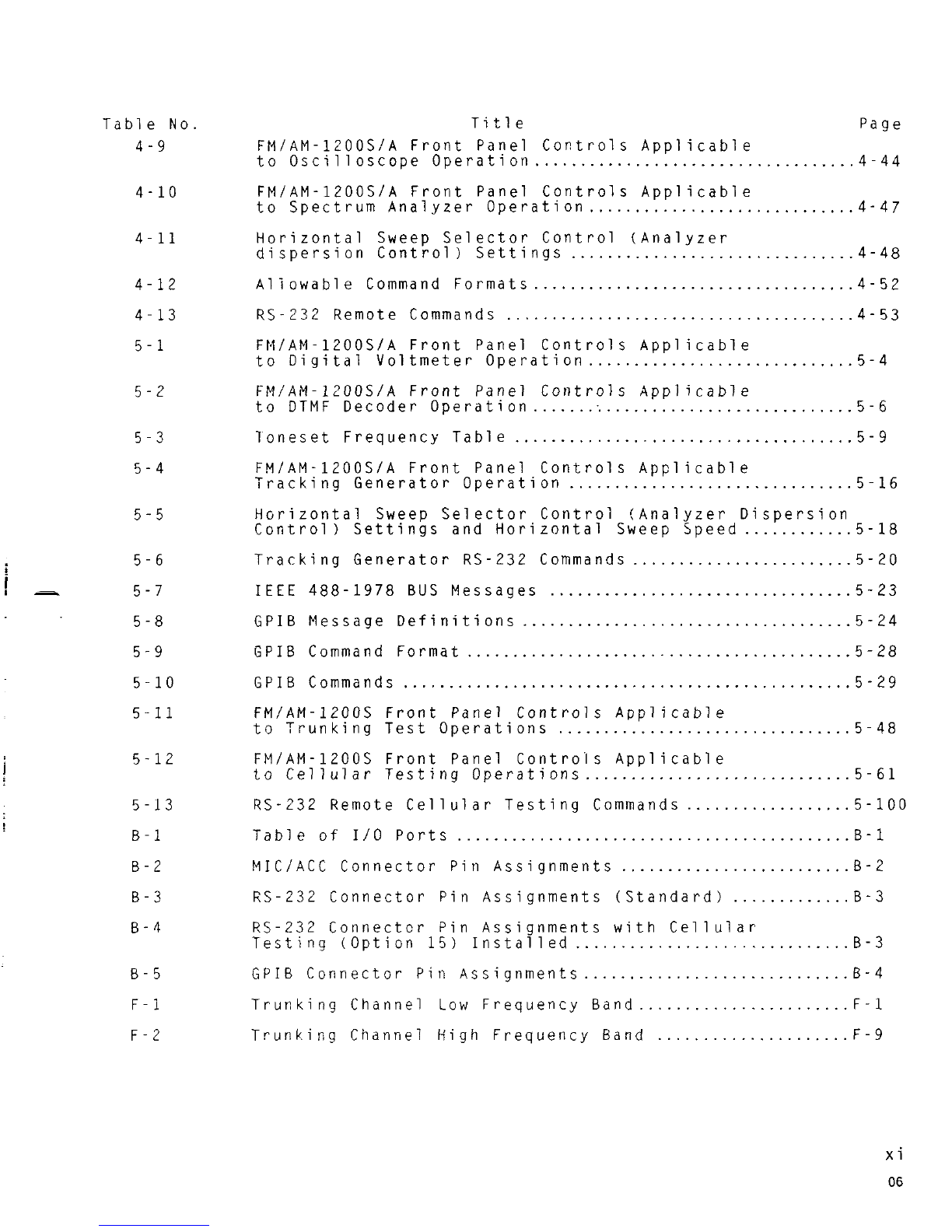
Table No
4
.
9 Title Page
FMIAM-1200SIA Front Panel Controls Appl icable
...................................
to Oscilloscope Operation 4.44
FMIAM-1200SlA Front Panel Controls Applicable
.............................
to Spectrum Analyzer Operation 4.47
Horizontal Sweep Selector Control (Analyzer
dispersion Control
)
Settings
...............................
4-48
A1 iowable Command Formats
...................................
4.52
......................................
RS-232 Remote Commands 4.53
FMIAM-1200S/A Front Panel Controls Applicable
.............................
to Digital Voltmeter Operation 5-4
FM/AM- 1200S/A Front Panel Controls Appl
i
cab1e
to DTMF Decoder Operation
...................................
5-6
.....................................
Toneset Frequency Table 5.9
FMIAM-1200SlA Front Panel Controls Appl icable
Tracking Generator Operation
...............................
5-16
Horizontal Sweep Selector Control (Analyzer Dispersion
Control
)
Settings and Horizontal Sweep Speed
............
5-18
Tracking Generator RS-232 Commands
........................
5-20
IEEE 488-1978 BUS Messages
.................................
5-23
GPIB Message Definitions
....................................
5-24
GPIB Command Format
..........................................
5-28
GPIB Commands
.................................................
5-29
FM/AM-1200s Front Panel Controls Applicable
to Trunking Test Operations
................................
5-48
FMIAM-1200s Front Panel Controls Applicable
to Cellular Testing Operations
.............................
5-61
RS-232 Remote Cellular Testing Commands
..................
5-100
Table of 1/0 Ports
...........................................
B-1
MICIACC Connector Pin Assignments
.........................
8-2
RS-232 Connector Pin Assignments (Standard)
.............
8-3
RS-232 Connectcr Pin Assignments with Cellular
Testing (Option
15)
Installed
..............................
€3-3
GPIB Connector Pin Assignments
.............................
B-4
Trunking Channel Low Frequency Band
.......................
F-1
Trunking Channel High Frequency Band
.....................
F-9

Cellular Channel Numbers and Assigned Center
Frequencies..
..................................................
G-1
Total Access Communications System (TACS) and Enhanced
Total Access Communications System (ETACS) Cellular
Telephone Channel Numbers and Assigned Center
Frequencies..
..................................................
H-1

SECTION
1
-
INTRODUCTION
1-1
GENERAL
The FM/AM-1200S/A is a microprocessor controlled, digitally synthesized
communication service monitor, which integrates the functions of several
different test instruments into a single, compact and portable unit.
Utilizing such features as a keyboard entry system, a Vacuum Fluorescent
Display for digital readout, processor controlled memory functions, a
CRT capable of displaying oscilloscope inputs and a DTMF encoder used
simultaneously with the variable audio generator for audio tone
encoding, the FMIAM-l200SIA incorporates the functions of the following
test equipment:
Signal Generator
Communication Receiver
Digital Voltmeter (Option)
Oscilloscope
1
kHz (Fixed) Tone Generator
Variable Tone Generator
(Programmable)
DTMF Encoder
DTMF Decoder (Option)
Power Meter
Frequency Error Meter
Modulation Meter
SINAO Meter
Audio Error Meter
Signal Strength Meter
DUPLEX Generator (with
a selectable offset)
Spectrum Analyzer
!FM/AM-1200s only)
Tracking Generator (Option,
FM/AM-1200s on1y)
These capabilities enable the FM/AM-1200S/A to be used in a wide range
i
of communication test functions associated with most types of simplex
and duplex transceiving equipment, including mobile telephone systems,
AM/FM/SSB transceivers, CB and two-way radio systems, repeaters, etc.
1-2
SIGNAL GENERATOR/RECEIVER
The FM/AM-1200S/A Signal Generator is capable of generating modulated or
unmodulated carrier signals within a range of 250 kHz to
999.9999
MHz
(in 100 Hz steps), at an output level which is continuously variable
from -20 to -127 dBm. The generated carrier signal may be
AM
or FM
modulated by internal modulation signals from the FM/AM-1200S/A tone
generators or by external sources applied through front panel modulation
input connectors defined in Section
3
of this manual. The signal
generator may also be voice-modulated and keyed through the front panel
microphone input connector. A1 1 of the above described modulation
sources, or any combination thereof, may be simultaneously applied to
the carrier signal. During signal generator operation, signals being
generated can be monitored by the FM/AM-1200S/A receiver and its
associated monitoring devices.
The signal generator also features a selectable offset frequency func-
tion to permit testing of duplex equipment, which receives and transmits
simultaneously on different frequencies. See paragraph 1-3 for addi-
tional information about this feature.
The FM/AM-1200S/A receiver is a triple conversion, superheterodyne
receiver, capable of monitoring communication signals within a range of
750 kHz to 999.9999 MHz, in 100 Hz steps. Signals may be received
"off-the-air" using an external antenna or by direct cable connection
through the front panel T/R Connector. Associated receiver monitoring
circuits include
a
frequency error meter, modulation meter, power meter,
SINAD meter, sigqal strength meter, frequency error and demodulated
audio counters, oscilloscope and spectrum analyzer !FM/AM-1200s only).
1-3 FM/AM-1200S/A CAPABILITIES
A
prime feature of the FM/AM-1200S/A is the capability of testing both
simplex and duplex communication equipment. Simplex operation
is
defined as any equipment that communicates
in
only one direction at a
time on the same frequency, including ordinary transmit-receive or
press-to-talk operation, voice operated carrier and other forms of
manual or automatic switching from transmit to receive. Duplex opera-
tion is characteristic of any equipment which transmits on one frequency
and receives on another frequency between two locations, such as mobile
telephone systems and repeaters.
In receive mode, the FM/AM-1200S/A receiver monitors incoming signals
received "off-the-air" or applied via direct cable connection through
the front panel T/R Connector. In
this
mode, the FM/AM-1700S/A signal
generator
is
inactive. In the generate mode, the FM/AM-1200S/A is
-
capable of generating modulated or unmodulated carrier signals while the
receiver circuits are simultaneously monitoring the generator.
In the duplex mode, the FM/AM-1200S/A has the capability of generating
-
and receiving signals simultaneously. While the receiver section of the
FM/AM-1200S/A is monitoring incoming signals transmitted by the UUT, the
FM/AM-1200S/A duplex generator
is
simultaneously generating signals to
stimulate the receiver section of the UUT. The frequency of the
.
generated signal from the FM/AM-1200S/A can be offset up to +49.99 MHz
!
from the receiving frequency in 10 kHz steps. Three methods of duplex
testing are available using the FM/AM-1200S/A. They are:
Duplex Testing using separate TransmitIReceive Lines
Duplex Testing using one common TransmitIReceive Line
"Off-the-air" Duplex testing
Tfie methods of duplex testing are described in detail in Section 4.
Table of contents


 manual")


