IGBT ILSCP24 User manual

IGBT DIMMER RACKS
IGBT DIMMER RACKS
ILSCP24 / ILSCP48
Made in U.S.A. For technical/sales assistance, call: 1-800-526-2731
P/N 85-5548
IMPORTANT: RETAIN THESE INSTRUCTIONS FOR THE END USER. DO NOT DISCARD.
WARNING: Before installation, disconnect power at circuit breakers or remove fuses to avoid electrical
shock or damage to the unit. It is recommended that an electrician perform this installation.
INSTALLATION AND
OPERATION MANUAL

2
IGBT DIMMER RACKS Installation
& Operation
Table of Contents
Installation Overview . . . . . . . . . . . . . . . . . . . . . . . . . . . . . . . . . . . . . . . . . . . . . . . . . . . . . . . . . . . . . . . . . . . . . . . . . . . . . . . . . . . . . . . . . . . . . . . . .4
Tools List . . . . . . . . . . . . . . . . . . . . . . . . . . . . . . . . . . . . . . . . . . . . . . . . . . . . . . . . . . . . . . . . . . . . . . . . . . . . . . . . . . . . . . . . . . . . . . . . . . . . . . . . . .4
Mechanical Considerations . . . . . . . . . . . . . . . . . . . . . . . . . . . . . . . . . . . . . . . . . . . . . . . . . . . . . . . . . . . . . . . . . . . . . . . . . . . . . . . . . . . . . . . . . . . . .5
Location . . . . . . . . . . . . . . . . . . . . . . . . . . . . . . . . . . . . . . . . . . . . . . . . . . . . . . . . . . . . . . . . . . . . . . . . . . . . . . . . . . . . . . . . . . . . . . . . . . . . . . .5
Clearances . . . . . . . . . . . . . . . . . . . . . . . . . . . . . . . . . . . . . . . . . . . . . . . . . . . . . . . . . . . . . . . . . . . . . . . . . . . . . . . . . . . . . . . . . . . . . . . . . . . . . .5
Route line and load wiring . . . . . . . . . . . . . . . . . . . . . . . . . . . . . . . . . . . . . . . . . . . . . . . . . . . . . . . . . . . . . . . . . . . . . . . . . . . . . . . . . . . . . . . . .5
Route control wiring . . . . . . . . . . . . . . . . . . . . . . . . . . . . . . . . . . . . . . . . . . . . . . . . . . . . . . . . . . . . . . . . . . . . . . . . . . . . . . . . . . . . . . . . . . . . . .5
Rack Overview . . . . . . . . . . . . . . . . . . . . . . . . . . . . . . . . . . . . . . . . . . . . . . . . . . . . . . . . . . . . . . . . . . . . . . . . . . . . . . . . . . . . . . . . . . . . . . . . . . . . . .6
Components . . . . . . . . . . . . . . . . . . . . . . . . . . . . . . . . . . . . . . . . . . . . . . . . . . . . . . . . . . . . . . . . . . . . . . . . . . . . . . . . . . . . . . . . . . . . . . . . . . . . . . . .7
Dimmer Rack . . . . . . . . . . . . . . . . . . . . . . . . . . . . . . . . . . . . . . . . . . . . . . . . . . . . . . . . . . . . . . . . . . . . . . . . . . . . . . . . . . . . . . . . . . . . . . . . . . .7
Rack Control Module (RCM) . . . . . . . . . . . . . . . . . . . . . . . . . . . . . . . . . . . . . . . . . . . . . . . . . . . . . . . . . . . . . . . . . . . . . . . . . . . . . . . . . . . . . . .8
Dimmer Modules . . . . . . . . . . . . . . . . . . . . . . . . . . . . . . . . . . . . . . . . . . . . . . . . . . . . . . . . . . . . . . . . . . . . . . . . . . . . . . . . . . . . . . . . . . . . . . . .8
Power Supply . . . . . . . . . . . . . . . . . . . . . . . . . . . . . . . . . . . . . . . . . . . . . . . . . . . . . . . . . . . . . . . . . . . . . . . . . . . . . . . . . . . . . . . . . . . . . . . . . .11
Blank Module . . . . . . . . . . . . . . . . . . . . . . . . . . . . . . . . . . . . . . . . . . . . . . . . . . . . . . . . . . . . . . . . . . . . . . . . . . . . . . . . . . . . . . . . . . . . . . . . . .11
Mounting the Rack . . . . . . . . . . . . . . . . . . . . . . . . . . . . . . . . . . . . . . . . . . . . . . . . . . . . . . . . . . . . . . . . . . . . . . . . . . . . . . . . . . . . . . . . . . . . . . . . . .12
Securing Rack To the Wall (optional) . . . . . . . . . . . . . . . . . . . . . . . . . . . . . . . . . . . . . . . . . . . . . . . . . . . . . . . . . . . . . . . . . . . . . . . . . . . . . . .12
Mounting Several Racks Together . . . . . . . . . . . . . . . . . . . . . . . . . . . . . . . . . . . . . . . . . . . . . . . . . . . . . . . . . . . . . . . . . . . . . . . . . . . . . . . . . .13
Mounting Using Vibration Isolation Fittings (optional) . . . . . . . . . . . . . . . . . . . . . . . . . . . . . . . . . . . . . . . . . . . . . . . . . . . . . . . . . . . . . . . . . .14
Securing Rack to the Wall with Vibration Isolation Pads (optional) . . . . . . . . . . . . . . . . . . . . . . . . . . . . . . . . . . . . . . . . . . . . . . . . . . . . . . . .15
Line Power Wiring . . . . . . . . . . . . . . . . . . . . . . . . . . . . . . . . . . . . . . . . . . . . . . . . . . . . . . . . . . . . . . . . . . . . . . . . . . . . . . . . . . . . . . . . . . . . . . . . . .16
Connection Order . . . . . . . . . . . . . . . . . . . . . . . . . . . . . . . . . . . . . . . . . . . . . . . . . . . . . . . . . . . . . . . . . . . . . . . . . . . . . . . . . . . . . . . . . . . . . . .16
Connecting Line Power Wiring (Single Racks) . . . . . . . . . . . . . . . . . . . . . . . . . . . . . . . . . . . . . . . . . . . . . . . . . . . . . . . . . . . . . . . . . . . . . . . .16
Busing Racks . . . . . . . . . . . . . . . . . . . . . . . . . . . . . . . . . . . . . . . . . . . . . . . . . . . . . . . . . . . . . . . . . . . . . . . . . . . . . . . . . . . . . . . . . . . . . . . . . . . . . .18
Load Wiring . . . . . . . . . . . . . . . . . . . . . . . . . . . . . . . . . . . . . . . . . . . . . . . . . . . . . . . . . . . . . . . . . . . . . . . . . . . . . . . . . . . . . . . . . . . . . . . . . . . . . . .20
Control Wiring . . . . . . . . . . . . . . . . . . . . . . . . . . . . . . . . . . . . . . . . . . . . . . . . . . . . . . . . . . . . . . . . . . . . . . . . . . . . . . . . . . . . . . . . . . . . . . . . . . . . .22
Installing DMX512 Control Wiring (Single Rack) . . . . . . . . . . . . . . . . . . . . . . . . . . . . . . . . . . . . . . . . . . . . . . . . . . . . . . . . . . . . . . . . . . . . .22
Installing DMX512 Control Wiring (Multiple Racks) . . . . . . . . . . . . . . . . . . . . . . . . . . . . . . . . . . . . . . . . . . . . . . . . . . . . . . . . . . . . . . . . . . .22
Installing Ethernet Control Wiring (Single Rack) . . . . . . . . . . . . . . . . . . . . . . . . . . . . . . . . . . . . . . . . . . . . . . . . . . . . . . . . . . . . . . . . . . . . . .22
Installing Ethernet Control Wiring (Multiple Racks) . . . . . . . . . . . . . . . . . . . . . . . . . . . . . . . . . . . . . . . . . . . . . . . . . . . . . . . . . . . . . . . . . . . .22
Finish and Test . . . . . . . . . . . . . . . . . . . . . . . . . . . . . . . . . . . . . . . . . . . . . . . . . . . . . . . . . . . . . . . . . . . . . . . . . . . . . . . . . . . . . . . . . . . . . . . . . . . . .24
Finish and Test Procedure . . . . . . . . . . . . . . . . . . . . . . . . . . . . . . . . . . . . . . . . . . . . . . . . . . . . . . . . . . . . . . . . . . . . . . . . . . . . . . . . . . . . . . . . .24
Attaching the Door . . . . . . . . . . . . . . . . . . . . . . . . . . . . . . . . . . . . . . . . . . . . . . . . . . . . . . . . . . . . . . . . . . . . . . . . . . . . . . . . . . . . . . . . . . . . . .25
Maintaining Cleanliness . . . . . . . . . . . . . . . . . . . . . . . . . . . . . . . . . . . . . . . . . . . . . . . . . . . . . . . . . . . . . . . . . . . . . . . . . . . . . . . . . . . . . . . . . .25
When using electrical equipment, basic safety precautions should always be followed including the following:
a) READ AD FOLLOW ALL SAFETY ISTRUCTIOS.
b) Do not use outdoors.
c) Do not mount near gas or electric heaters.
d) Equipment should be mounted in locations and at heights where it will not readily be subjected to tampering
by unauthorized personnel.
e) The use of accessory equipment not recommended by the manufacturer may cause an unsafe condition.
f) Do not use this equipment for other than intended use.
g) Refer service to qualified personnel.
SAVE THESE ISTRUCTIOS.
IMPORTANT SAFEGUARDS

IGBT DIMMER RACKS
Installation
& Operation
3
Installing Dimmer and Control Modules . . . . . . . . . . . . . . . . . . . . . . . . . . . . . . . . . . . . . . . . . . . . . . . . . . . . . . . . . . . . . . . . . . . . . . . . . . . . . . . . .26
Installing Dimmer Modules . . . . . . . . . . . . . . . . . . . . . . . . . . . . . . . . . . . . . . . . . . . . . . . . . . . . . . . . . . . . . . . . . . . . . . . . . . . . . . . . . . . . . . .26
Installing the Rack Control Module (ILSCPRCM) . . . . . . . . . . . . . . . . . . . . . . . . . . . . . . . . . . . . . . . . . . . . . . . . . . . . . . . . . . . . . . . . . . . . .27
Installing the Lytemode Power Supply Module (ILSLMPSC) .. . . . . . . . . . . . . . . . . . . . . . . . . . . . . . . . . . . . . . . . . . . . . . . . . . . . . . . . . . .27
Installing a Blank Module (CPBLANK) . . . . . . . . . . . . . . . . . . . . . . . . . . . . . . . . . . . . . . . . . . . . . . . . . . . . . . . . . . . . . . . . . . . . . . . . . . . . .27
Configuration Using RCM LCD Menu . . . . . . . . . . . . . . . . . . . . . . . . . . . . . . . . . . . . . . . . . . . . . . . . . . . . . . . . . . . . . . . . . . . . . . . . . . . . . . . . . .28
Overview . . . . . . . . . . . . . . . . . . . . . . . . . . . . . . . . . . . . . . . . . . . . . . . . . . . . . . . . . . . . . . . . . . . . . . . . . . . . . . . . . . . . . . . . . . . . . . . . . . . . . .28
LCD Menu Operation . . . . . . . . . . . . . . . . . . . . . . . . . . . . . . . . . . . . . . . . . . . . . . . . . . . . . . . . . . . . . . . . . . . . . . . . . . . . . . . . . . . . . . . . . . . .28
Menu System . . . . . . . . . . . . . . . . . . . . . . . . . . . . . . . . . . . . . . . . . . . . . . . . . . . . . . . . . . . . . . . . . . . . . . . . . . . . . . . . . . . . . . . . . . . . . . . . . .29
Guardian Overview . . . . . . . . . . . . . . . . . . . . . . . . . . . . . . . . . . . . . . . . . . . . . . . . . . . . . . . . . . . . . . . . . . . . . . . . . . . . . . . . . . . . . . . . . . . . . . . . .30
Getting Started with Guardian . . . . . . . . . . . . . . . . . . . . . . . . . . . . . . . . . . . . . . . . . . . . . . . . . . . . . . . . . . . . . . . . . . . . . . . . . . . . . . . . . . . . . . . . .30
Connecting a PC to the Capio Plus System . . . . . . . . . . . . . . . . . . . . . . . . . . . . . . . . . . . . . . . . . . . . . . . . . . . . . . . . . . . . . . . . . . . . . . . . . . . . . . .31
Configuring RCM Using Guardian . . . . . . . . . . . . . . . . . . . . . . . . . . . . . . . . . . . . . . . . . . . . . . . . . . . . . . . . . . . . . . . . . . . . . . . . . . . . . . . . . . . . .32
RCM Setup . . . . . . . . . . . . . . . . . . . . . . . . . . . . . . . . . . . . . . . . . . . . . . . . . . . . . . . . . . . . . . . . . . . . . . . . . . . . . . . . . . . . . . . . . . . . . . . . . . . .32
Dimmer Setup . . . . . . . . . . . . . . . . . . . . . . . . . . . . . . . . . . . . . . . . . . . . . . . . . . . . . . . . . . . . . . . . . . . . . . . . . . . . . . . . . . . . . . . . . . . . . . . . . .33
Dimmer Inputs . . . . . . . . . . . . . . . . . . . . . . . . . . . . . . . . . . . . . . . . . . . . . . . . . . . . . . . . . . . . . . . . . . . . . . . . . . . . . . . . . . . . . . . . . . . . . . . . .35
Parked Dimmers . . . . . . . . . . . . . . . . . . . . . . . . . . . . . . . . . . . . . . . . . . . . . . . . . . . . . . . . . . . . . . . . . . . . . . . . . . . . . . . . . . . . . . . . . . . . . . . .37
Local Presets . . . . . . . . . . . . . . . . . . . . . . . . . . . . . . . . . . . . . . . . . . . . . . . . . . . . . . . . . . . . . . . . . . . . . . . . . . . . . . . . . . . . . . . . . . . . . . . . . . .38
Save RCM Configuration . . . . . . . . . . . . . . . . . . . . . . . . . . . . . . . . . . . . . . . . . . . . . . . . . . . . . . . . . . . . . . . . . . . . . . . . . . . . . . . . . . . . . . . . .39
Basic Guardian Operations . . . . . . . . . . . . . . . . . . . . . . . . . . . . . . . . . . . . . . . . . . . . . . . . . . . . . . . . . . . . . . . . . . . . . . . . . . . . . . . . . . . . . . . . . . . .40
Discovery . . . . . . . . . . . . . . . . . . . . . . . . . . . . . . . . . . . . . . . . . . . . . . . . . . . . . . . . . . . . . . . . . . . . . . . . . . . . . . . . . . . . . . . . . . . . . . . . . . . . .40
Capio Plus System Configuration . . . . . . . . . . . . . . . . . . . . . . . . . . . . . . . . . . . . . . . . . . . . . . . . . . . . . . . . . . . . . . . . . . . . . . . . . . . . . . . . . . .40
Administrative Mode . . . . . . . . . . . . . . . . . . . . . . . . . . . . . . . . . . . . . . . . . . . . . . . . . . . . . . . . . . . . . . . . . . . . . . . . . . . . . . . . . . . . . . . . . . . .40
Saving Files . . . . . . . . . . . . . . . . . . . . . . . . . . . . . . . . . . . . . . . . . . . . . . . . . . . . . . . . . . . . . . . . . . . . . . . . . . . . . . . . . . . . . . . . . . . . . . . . . . . .41
System Polling (Guardian NT Only) . . . . . . . . . . . . . . . . . . . . . . . . . . . . . . . . . . . . . . . . . . . . . . . . . . . . . . . . . . . . . . . . . . . . . . . . . . . . . . . .41
Dimmer Load Snapshot (Guardian NT Only) . . . . . . . . . . . . . . . . . . . . . . . . . . . . . . . . . . . . . . . . . . . . . . . . . . . . . . . . . . . . . . . . . . . . . . . . .42
Total Load Reporting (Guardian NT Only) . . . . . . . . . . . . . . . . . . . . . . . . . . . . . . . . . . . . . . . . . . . . . . . . . . . . . . . . . . . . . . . . . . . . . . . . . . .42
Guardian Setup . . . . . . . . . . . . . . . . . . . . . . . . . . . . . . . . . . . . . . . . . . . . . . . . . . . . . . . . . . . . . . . . . . . . . . . . . . . . . . . . . . . . . . . . . . . . . . . . . . . . .43
Serial Port (non-Pathport RCM only) . . . . . . . . . . . . . . . . . . . . . . . . . . . . . . . . . . . . . . . . . . . . . . . . . . . . . . . . . . . . . . . . . . . . . . . . . . . . . . . .43
Multicast Interface . . . . . . . . . . . . . . . . . . . . . . . . . . . . . . . . . . . . . . . . . . . . . . . . . . . . . . . . . . . . . . . . . . . . . . . . . . . . . . . . . . . . . . . . . . . . . .43
Connect To Pathport Network . . . . . . . . . . . . . . . . . . . . . . . . . . . . . . . . . . . . . . . . . . . . . . . . . . . . . . . . . . . . . . . . . . . . . . . . . . . . . . . . . . . . .43
Report Logging (Guardian NT Only) . . . . . . . . . . . . . . . . . . . . . . . . . . . . . . . . . . . . . . . . . . . . . . . . . . . . . . . . . . . . . . . . . . . . . . . . . . . . . . . .44
Email Notifications (Guardian NT Only) . . . . . . . . . . . . . . . . . . . . . . . . . . . . . . . . . . . . . . . . . . . . . . . . . . . . . . . . . . . . . . . . . . . . . . . . . . . . .44
Dimmer Status (Guardian NT Only) . . . . . . . . . . . . . . . . . . . . . . . . . . . . . . . . . . . . . . . . . . . . . . . . . . . . . . . . . . . . . . . . . . . . . . . . . . . . . . . . . . . .45
Troubleshooting . . . . . . . . . . . . . . . . . . . . . . . . . . . . . . . . . . . . . . . . . . . . . . . . . . . . . . . . . . . . . . . . . . . . . . . . . . . . . . . . . . . . . . . . . . . . . . . . . . . .47
Checklist . . . . . . . . . . . . . . . . . . . . . . . . . . . . . . . . . . . . . . . . . . . . . . . . . . . . . . . . . . . . . . . . . . . . . . . . . . . . . . . . . . . . . . . . . . . . . . . . . . . . . . . . . .48
Appendix A: Standard Wiring . . . . . . . . . . . . . . . . . . . . . . . . . . . . . . . . . . . . . . . . . . . . . . . . . . . . . . . . . . . . . . . . . . . . . . . . . . . . . . . . . . . . . . . . .49
DMX512 . . . . . . . . . . . . . . . . . . . . . . . . . . . . . . . . . . . . . . . . . . . . . . . . . . . . . . . . . . . . . . . . . . . . . . . . . . . . . . . . . . . . . . . . . . . . . . . . . . . . . .49
Lytemode ILS Networks . . . . . . . . . . . . . . . . . . . . . . . . . . . . . . . . . . . . . . . . . . . . . . . . . . . . . . . . . . . . . . . . . . . . . . . . . . . . . . . . . . . . . . . . . 49
Termination of Shielded Cable . . . . . . . . . . . . . . . . . . . . . . . . . . . . . . . . . . . . . . . . . . . . . . . . . . . . . . . . . . . . . . . . . . . . . . . . . . . . . . . . . . . . .50
Termination of Ethernet Cable . . . . . . . . . . . . . . . . . . . . . . . . . . . . . . . . . . . . . . . . . . . . . . . . . . . . . . . . . . . . . . . . . . . . . . . . . . . . . . . . . . . . .50
Appendix B: Specifications . . . . . . . . . . . . . . . . . . . . . . . . . . . . . . . . . . . . . . . . . . . . . . . . . . . . . . . . . . . . . . . . . . . . . . . . . . . . . . . . . . . . . . . . . . .51
Capio Plus IGBT Dimmer Rack (ILSCP24 / ILSCP48) . . . . . . . . . . . . . . . . . . . . . . . . . . . . . . . . . . . . . . . . . . . . . . . . . . . . . . . . . . . . . . . . . 51
Capio Plus Rack Control Module (ILSCPRCM) . . . . . . . . . . . . . . . . . . . . . . . . . . . . . . . . . . . . . . . . . . . . . . . . . . . . . . . . . . . . . . . . . . . . . . 52
Capio Plus Dimmer Rack Modules .. . . . . . . . . . . . . . . . . . . . . . . . . . . . . . . . . . . . . . . . . . . . . . . . . . . . . . . . . . . . . . . . . . . . . . . . . . . . . . . . .52
Notice To Contractor . . . . . . . . . . . . . . . . . . . . . . . . . . . . . . . . . . . . . . . . . . . . . . . . . . . . . . . . . . . . . . . . . . . . . . . . . . . . . . . . . . . . . . . . . . . . . . . .53
Engineering Check-Out Request Form . . . . . . . . . . . . . . . . . . . . . . . . . . . . . . . . . . . . . . . . . . . . . . . . . . . . . . . . . . . . . . . . . . . . . . . . . . . . . . . . . . .54
Table of Contents (continued)

4
IGBT DIMMER RACKS Installation
& Operation
___ Drill for mounting holes ___ Wire stripper
___ Hammer (for removing knockouts) ___ Heat shrink tubing
___ Philips screwdriver ___ Pencil
___ Small flat screwdriver ___ Knife
___ Flat screwdriver ___ Conduit and fittings
___ Adjustable wrench ___ Urethane filler foam
___ Ratchet and assorted sockets ___ Digital voltmeter/RMS
___ Wire cutter ___ 110-style punch down tool (for Ethernet connections)
ote: This is a basic list. You may need additional tools.
Tools List
The document provides installation instructions for all configurations of Capio Plus IGBT Dimmer Racks (ILSCP24 and ILSCP48).
Please read all instructions before installing this product.
The Capio Plus IGBT Dimmer Racks are shipped from the factory ready to install. The door, dimmer modules and the Rack Control
Module(s) may be shipped separately. The following steps are required to successfully install a Capio Plus IGBT Dimmer Rack:
Review this document completely
Familiarize yourself with the installation procedure before you start.
Unpack and inspect your equipment
Check for physical damage to container(s). Compare the equipment you received with your packing list.
Gather tools
You will need the tools listed below.
Pick an appropriate location for the rack
The rack should be installed on an industrial grade floor. The room in which it is installed should have sufficient volume to allow
exhaust air to circulate and cool. For more details and clearance requirements, refer to "Mechanical Considerations" on page 5 and con-
sult system drawings. For environmental considerations refer to "Specifications" on page 51.
Plan your wire routings and connection order
Decide where your line, load, and control wiring will enter the cabinet.
Cut openings and remove knockouts in the rack panels as required for conduit or busway entrance
Perform all conduit connections to the rack before it is permanently installed. Be sure to remove all knockout pieces and debris from
the cabinet. Seal all connections on the rack to allow for proper airflow.
Install Rack
Mount rack(s). Terminate all line, load, and control wires following the directions provided in this manual. Clean up work site and
rack(s) for check out by Philips Lighting Controls Technical Services.
Contact Philips Lighting Controls
Contact Philips Lighting Controls Technical Services when rack(s) is (are) installed and ready for Engineering Check Out. See "ENGI-
NEERING CHECK-OUT REQUEST FORM" at the end of this manual.
Installation Overview

IGBT DIMMER RACKS
Installation
& Operation
5
: You must have access to a main circuit breaker or other power disconnect device before installing any wiring. Be
sure that power is disconnected by removing fuses or turning circuit breaker off before installation. Installing the device with
power on may expose you to dangerous voltage and damage the device. A qualified electrician should perform this installation.
: This product is intended for installation in accordance with the National Electrical Code® and local or Federal
code specifications. To ensure full compliance with all codes and regulations, check with your local electrical inspector prior to
installation. To prevent electrical shock, turn off power at fuse box before installation.
: Capio Plus IGBT Dimmer Rack electronics operate at line voltage potential! They are electrically isolated by
optically coupling the input and output data streams. DO NOT connect non-isolated test equipment to the circuit common point
in the dimmers. Destruction of the dimmer and test equipment and possible injury to personnel will result. Measurements of
input and output voltages must be referenced to Power Line Neutral only.
: This equipment generates, uses, and can radiate radio frequency energy and if not installed and used in accor-
dance with this instruction manual may cause interference to radio communications. It has been tested and found to comply
with the limits for a Class A computing device pursuant to Subpart J of Part 15 of FCC Rules, which are designed to provide
reasonable protection against such interference when operated in a commercial environment. Operation of this equipment in a
residential area is likely to cause interference in which case the user, at his own expense, will be required to take whatever
measures may be required to correct the interference. If you need help, consult your dealer. You may also find the following
booklet helpful: How to Identify and Resolve Radio-TV Interference Problems. This booklet is available from the U.S.
Government Printing Office, Washington, DC 20402, stock no. 004-000-00345-4.
LOCATION
The rack should be installed on an industrial grade floor with sufficient load capacity to support it. For rack weights and dimensions,
see "Specifications" on page 51. The room must be dry and must have sufficient volume to allow exhaust air to circulate and cool. If
an undersized room is used, it must have air handling which is adequate to maintain the specified ambient temperature range (see
"Specifications" on page 51).
WARIG! Rated for indoor use only.
CLEARANCES
The rack must have a minimum of 18 inches of clear space above it for exhaust air and a minimum of 36 inches of clear floor space
in front of it. Single racks or the right-most rack of bused racks require 2 inches of space to the right. See Figure 1 on next page for
rack clearances. Refer to the National Electrical Code® and local electrical codes to determine whether additional clearance around
the rack is required.
ROUTE LINE AND LOAD WIRING
Line Power wiring may enter the rack through removable plates on the top or bottom. See Figure 1 on next page.
ROUTE CONTROL WIRING
DMX512 and/or Ethernet control wiring may enter the rack through knockouts in the top or bottom of the rack. Please note that the
low-voltage wiring compartment is located at the top of the rack. If control wiring enters the rack through the bottom, it may be run
through either of the hollow sides of the rack to the top compartment. See "Control Wiring" on page 21 for details.
Control wires may also enter through side knockouts (see Figure 12 for knockout placement.) Load and Line wires should always
enter the dimmer rack through a knockout via conduit. Check your local electrical code for more information.
You must have access to a main circuit breaker or other power disconnect device before installing any wiring. Failure to disconnect
power before installing or servicing your dimmer rack may result in injury or death.
Mechanical Considerations
Do not energize the Capio
Plus IGBT Dimmer Rack until the wiring has been approved by a technician from Philips Lighting Controls. Contact Technical Support at
+1-800-526-2731 to arrange for approval. Refer to page 53.

6
IGBT DIMMER RACKS Installation
& Operation
Rack Overview
Knockouts for control wire entry
Removable panel for line/load wire entry
Removable
panel for
line/load
Knockouts
2" to right of
rightmost rack
18" above rack
36" in front of rack
82.0"
(208.28 cm)
6.25"
15.9 cm
(Opening)
6.3125"
16.03 cm
0.875"
2.2 cm
12.5"
31.8 cm
(Opening)
Air filter channel
25.75"
(65.41 cm)
14.25"
(36.20 cm)
Figure 1: Clearances and Wiring Entry

IGBT DIMMER RACKS
Installation
& Operation
7
Figure 2: Dimmer Rack Components
DIMMER RACK
Removable wiring cover
Neutral wiring bus
Rack Control Module
(RCM) upper back plane
Phase A feed lug
Phase B feed lug
Ground wiring bus
(optional)
Phase C feed lug
Removable wiring cover
Exhaust fan
Dimmer lower
back plane
Dimmer module
power/data connectors
Load terminal blocks
Back plane
flex jumpers
Leveling feet
Components

8
IGBT DIMMER RACKS Installation
& Operation
DIMMER MODULES
Figure 3: Rack Control Module (ILSCPRCM)
RACK CONTROL MODULE (RCM)
Figure 4: 15A and 20A IGBT Dimmer Modules (CP15HP, CP20HP)
Power/data connector
Circuit breakers with interlocking latch
Test (focus) buttons
and status indicators
Heat sink
Power connector
Data connector
Ethernet port
Diagnostic port
Menu display
Menu controls
Components (continued)

IGBT DIMMER RACKS
Installation
& Operation
9
Components (continued)
Figure 5: Single 50A IGBT Dimmer Module (CP50)
Power/data connector
Circuit breaker with interlocking latch
Test (focus) buttons
and status indicators
Heat sink
Figure 6: 15A and 20A Constant Circuit Module (CP15CC, CP20CC)
Power/data connector
Circuit breakers with interlocking latch
ote: Maximum of 10 per ILSCR48
or 5 per ILSCR24)

10
IGBT DIMMER RACKS Installation
& Operation
Components (continued)
Figure 7: 15A and 20A Non-Dim Module (CP15ND, CP20ND)
Heat Sink
Test (focus) button and
status indicators
Power/data connector
Circuit breaker with interlocking latch
Figure 8: SINGLE 20A PowerSpec® HDF Fluorescent Dimmer Module (CP20HDF) *
Heat Sink
Test (focus) buttons
and status indicators
Power/data connector
Circuit breaker with interlocking latch
* For dimming of Entertainment Technology and Lightolier Controls® electronic fluorescent dimming ballasts.
ote: One slot per HDF lighting circuit.

IGBT DIMMER RACKS
Installation
& Operation
11
BLANK MODULE
Components (continued)
Figure 9: Lytemode® Power Supply Module (ILSLMPSC) *
POWER SUPPLY
Data connector
Power connector
LED Status
Indicator
For use with Lightolier Controls® Lytemode® Architectural Lighting Control products.
ote: Installed in lower slot under ILSCPRCM of upper back plane.
Figure 10: Blank Module (CPBLANK)
ote: A blank module is equal to a single dimmer module in height. (1.5").

12
IGBT DIMMER RACKS Installation
& Operation
Warning!
Capio Plus IGBT Dimmer Racks utilize dangerous voltages. Installation should be performed by trained per-
sonnel only. To prevent electrical shock, turn off power at fuse box before proceeding.
: This product is intended for installation in accordance with the National Electrical Code® and local or Federal
code specifications. To ensure full compliance with all codes and regulations, check with your local electrical inspector prior to
installation. To prevent electrical shock, turn off power at fuse box before installation.
: To reduce the risk of fire or shock hazard, DO NOT expose this equipment to rain or other moisture.
SECURING RACK TO THE WALL (OPTIONAL )
If racks will be bused, please see "Busing Racks" on page 17
before mounting.
1. Mark hole placement on back of rack (placement at
installer’s discretion - see Figure 11).
2. Drill through back of rack.
3. Attach to wall with 3/8" or larger lag bolts.
Mounting the Rack
Figure 11: Suggested Hole Placement For Wall Mounting
Locate optional wall mount holes
in approximate locations shown

IGBT DIMMER RACKS
Installation
& Operation
13
MOUNTING SEVERAL RACKS TOGETHER
If racks will be bused, please see "Busing Racks" on page 17
before mounting.
Racks may be bolted together.
1. Remove the four bolt-through knockouts (two at top, two
at bottom, front and back - see Figure 12).
2. If you plan to run control cables from rack to rack, remove
the necessary knockouts before bolting the racks together
(see Figure 20 on page 22).
3. Bolt adjacent racks together using 3/8-16 UNC x 5/8" bolts
and locking nuts.
Mounting the Rack (continued)
Figure 12: Side Knockout Placement
Bolt-through knockouts
Bolt-through
knockouts
Control
wiring
knockout
14
IGBT DIMMER RACKS Installation
& Operation
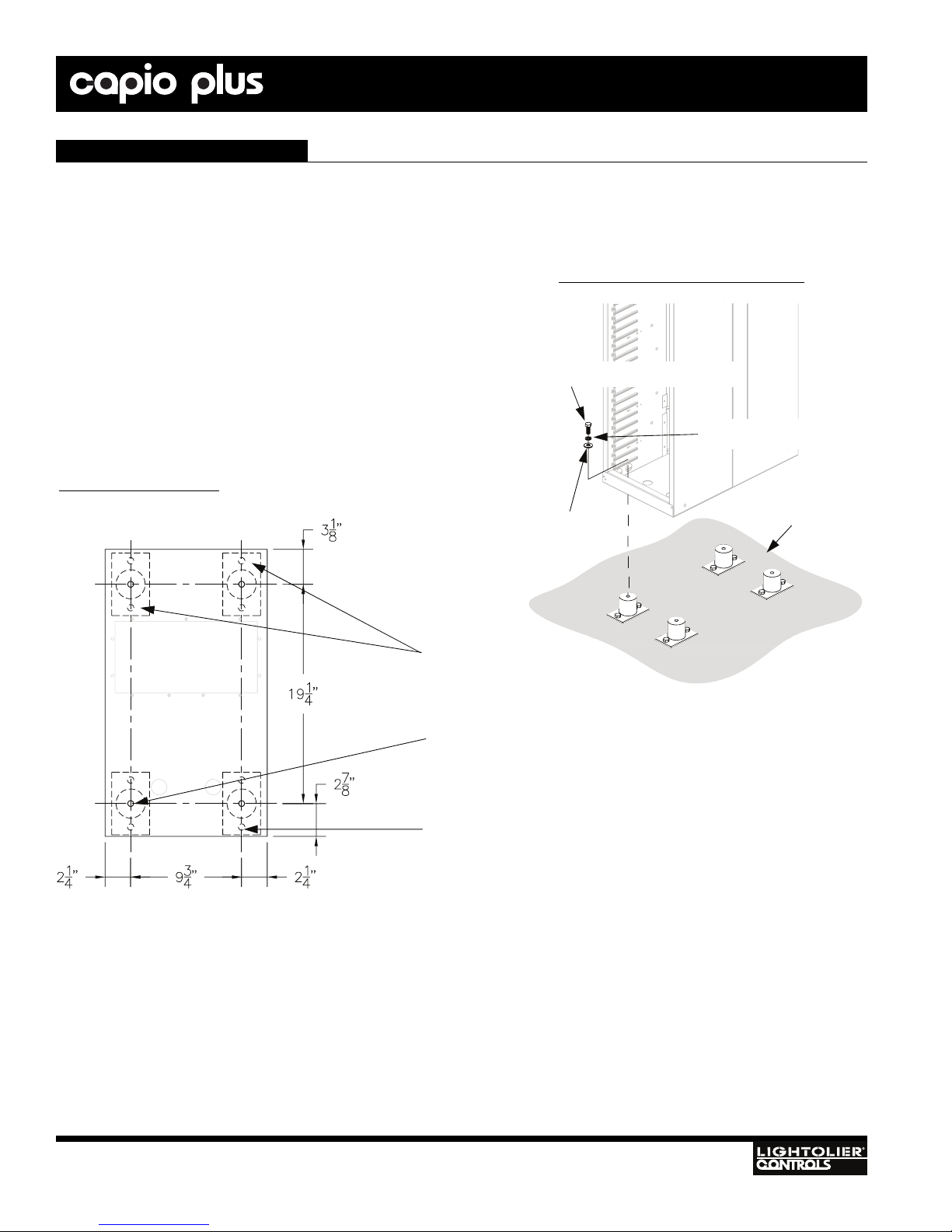
MOUNTING USING VIBRATION ISOLATION FITTINGS (OPTIONAL)
If racks will be bused, please see "Busing Racks" on page 17 before mount-
ing.
Vibration isolation fittings are available for floor mounting (Lightolier
Controls® part numbers CPPAD24 or CPPAD48).
1. Remove rack leveling feet.
2. Use Figure 14 to mark hole placement on floor.
3. Align the center of the vibration fitting over the hole location. Mark the
positions of two fitting bolts for each vibration fitting.
4. Drill holes and attach fittings to floor with 5/16" bolts.
5. Slide rack into position.
6. Attach to floor vibration fittings using 3/8-16 UNC x 5/8" bolts as shown
in Figure 13.
Mounting the Rack (continued)
Figure 13: Attaching To Isolation Fittings
3/8-16 UNC x 5/8" bolt
3/8" flat washer
3/8" split-ring lock washer
Floor
Figure 14: Hole Placement
Isolation pads
9/16" holes
(in rack bottom)
REAR OF RACK
11/32" holes

IGBT DIMMER RACKS
Installation
& Operation
15
SECURING RACK TO THE WALL WITH VIBRATION
ISOLATION PADS (OPTIONAL )
Vibration isolation fittings are available for wall mounting
(Lightolier Controls part numbers CPPAD24 or CPPAD48).
If racks will be bused, please see "Busing Racks" on page 17
before mounting.
1. Mark hole placement on wall and on back of rack (place-
ment at installer’s discretion - see Figure 11 on page 11).
2. Align the center of the vibration fitting over the hole loca-
tion. Mark the positions of the two fitting bolts for each
vibration fitting.
3. Drill holes and attach fittings to wall with 5/16" lag bolts.
4. Drill through back of rack.
5. Move rack into position.
6. Attach to wall vibration fittings with 5/8-16 UNC x 5/8"
bolts as shown in Figure 15 . (See alsoFigure 13 on page
13.)
Mounting the Rack (continued)
Figure 15: Attaching to Wall Using Isolation Pads
Wall-
mount
vibration
isolation
fittings
Floor mount
Isolation pads

16
IGBT DIMMER RACKS Installation
& Operation
CONNECTION ORDER
The Capio Plus IGBT Dimmer Rack is designed to be wired from the front. For this reason it makes sense to complete the connec-
tions at the back of the rack first, and the ones at the front last. We recommend connecting the Line Power wiring and Grounds (if
applicable) first, and the Load Neutral and Load Hot wires last.
Important: Dress wires neatly. Extra wire inside the rack can restrict airflow.
CONNECTING LINE POWER WIRING (SINGLE RACKS )
You must have access to a main circuit breaker or other power disconnect device before installing any wiring.
Failure to disconnect power before installing or servicing your dimmer rack may result in injury or death.
1. Run line power wiring from the power source to the top or bottom of the rack. See "Mechanical Considerations" on page 4 for
feed routing.
2. Remove the wire access panel (Figure 16).
3. Punch holes and install conduit fittings <OR> insert lining materials in the access panel opening.
4. Replace the wire access panel if using conduit.
5. Pull the line power cables through the prepared openings.
: Wire openings must have fittings or linings to protect wire and cable insulation and to prevent air leaks.
6. Strip 1-3/8" of insulation from the end of each cable.
7. Terminate the Phase, Neutral, and Ground wires to their lugs. Line connections are labeled A, B and C (Figure 16). If necessary,
the main lugs may be re-oriented for the direction of feed.
8. Tighten the main lug set screws to the torque termination shown on the label inside the right wall of the rack (shown in part
below).
TERMINAL WIRE RANGE TIGHTENING TORQUE (IN-LBS)
Main (Line) (See Main Breaker, if used)
2: 600 kCM-2:20
(See Main Breaker, if used)
500
Main (Neutral) 2:600 kCM - 2:2/0 500
Load (20A) 1: #6-#20
2: #10-#20 10.6 - 13.3
Load (50A) #4 - #6
#1/0 - #2
45
50
Load Neutral #4 - #14 AWG
#10 -#14: 35
#8: 40
#4 - #6: 45
Ground #2/0 - #14 AWG
#10 - #14: 35
#8: 40
#4 - #6: 45
#3 - 2/0: 50
Ground Bus #6 - #14 AWG
#10 - #14: 35
#8: 40
#6: 45
!
Line Power Wiring

IGBT DIMMER RACKS
Installation
& Operation
17
Line Power Wiring (continued)
CAUTIO: Failure to use proper torque when tightening set screws will cause premature failure of the equipment!
CAUTIO: Refer to local and/or National Electrical Code® for cable specifications. Failure to use the proper cable can
result in damage to the equipment or danger to persons.
CAUTIO: Use 90° copper wire only!
Important: If different UL-listed lugs are substituted for the supplied UL-listed lugs, tighten these to their specifications and update
the torque label on the rack.
Phase A feed lug
Neutral feed lug
Phase B feed lug
Ground feed lug
Phase C feed lug
Bottom wire
access panel
Top wire
access panel
Figure 16: Wire Access and Line Power Lugs
!
!
!

18
IGBT DIMMER RACKS Installation
& Operation
Capio Plus IGBT Dimmer Racks may be bused together using the optional busing kit. To bus racks, you will need to remove the pan-
els as described below before the racks are bolted together or secured to a wall.
To bus two or more racks together:
1. Determine which panels need to be removed. (Example: If you are busing two racks, the panel on the right side of the left-hand rack
and the panel on the left side of the right-hand rack need to be removed.)
2. Remove the eight screws as shown in Figure 17 from each panel you are removing. Save these screws - you will need them in Step
8. Remove the panels and properly recycle the material.
3. Level the racks and bolt them together (see "Mounting Several Racks Together" on page 12).
4. Remove the phase lugs from the rack(s) that will not be fed from the main.
5. Loosely attach the phase A, B, and C bus bars as shown in Figure 18. Leave hardware loose until all bus bars are in place.
6. Loosely attach the Neutral bus bar as shown in Figure 18.
7. Tighten all bolts.
8. Insert the plastic rack divider (Figure 17) between the two racks. Attach it to the left-hand rack using the eight screws and screw
holes from Step 2.
: Do not operate bused racks without the plastic divider in place. Air leaks can inhibit rack ventilation, causing
dimmers to overheat and shut down.
Figure 17: Busing Kit Parts and Removing Busing Panel
Removable
busing panel
Screws
Plastic rack divider
Neutral bus bar
3/8" flat
washer
3/8" lock
washer
3/8-16
lock nut
Phase bus bar
3/8" - 16 X 1”
hex head bolt Screws
!
Busing Racks

IGBT DIMMER RACKS
Installation
& Operation
19
ote: In the examples below, the mains feed is shown connected to the left rack, with the right rack’s lugs removed. Your application
may be different, but the principle is the same.
Busing Racks (continued)
Figure 18: Attaching Bus Bars
Top feed
deefmottoBdeefpoT
Bottom feed

20
IGBT DIMMER RACKS Installation
& Operation
To connect load wiring:
1. Run load wiring to the top or bottom of the rack. If your rack has the optional Ground Bus, separate the load ground wires and route
them to this bus.
ote: Load wires should not be fed through the sides of the enclosure.
2. If you have ground wires from your loads, strip 3/8" of insulation from them and connect using the torque values shown in the table
at right.
3. Separate the load neutral wires and route them to the load neutral terminals located on the neutral bus bar in the center of the rack
(see Figure 2 on page 6). Strip 3/8” of insulation from the wires and terminate them using the torque values in the table below.
CAUTIO: Use a separate wire for each neutral. Do not use common neutrals.
4. Route the load hot wires to their individual connections. The load hot terminals are located on the dimmer back plane on the left
side of the rack (see Figure 2 on page 6 and Figure 19 on the following page). If the load wires are top fed, work from top to bot-
tom on the dimmer back plane as you connect the hots for each circuit in turn. If they are bottom fed, work from the bottom up.
Important: Follow the circuit numbers printed on the load terminal connectors. The load terminals are not sequential from top to bot-
tom! When wiring more than one rack, remember to add 96 to the numbers in the second rack, 192 to the third, etc.
5. Strip 3/8" of insulation from the load wires. Do not exceed the bend radius shown in Figure 19 when inserting load wires.
6. Tighten all terminations to the torque values shown in the table below.
7. Dress load wires to the back of the rack.
Load Wiring
TERMINAL WIRE SIZE TIGHTENING TORQUE
(IN-LBS)
20A Load Lugs #20 - #6 AWG 10.6 - 13.3
Neutral Bus
#10 - #14 AWG 50
#8 AWG 50
#6 AWG 50
Ground Bus
#10 - #14 AWG 50
#8 AWG 50
#6 AWG 50
!
This manual suits for next models
3
Table of contents
Popular Dimmer manuals by other brands


Hoftronic
Hoftronic 4406554 user manual

Marmitek
Marmitek LMM32 user manual

Lutron Electronics
Lutron Electronics Spacer System SPS-300LD installation instructions

Casambi
Casambi CBU-TED-LR Product Technical Specification

QOLSYS
QOLSYS IQ Dimmer quick start guide

Lucci LEDlux
Lucci LEDlux 290998 installation instructions


