Company NA Omega Mk2 User manual

USER MANUAL
Omega Mk2

BEFORE YOU BEGIN
What’s included
►1 x OMEGA Mk2 dimmer unit
►1 xWarranty Card
►1 xUser Manual
Unpacking
After receiving a package, carefully unpack the it, check the contents to ensure that all parts are
present, and have been received in good condition. Notify the shipper immediately and retain packing
material for inspection if any parts appear damaged from shipping or the carton it self sho s signs of
mishandling. Save the carton and all packing materials. In the event that a fixture must be returned to the
factory, it is important that the fixture be returned in the original factory box and packing.
P wer
Before po ering on the unit, make sure the line voltage you are applying is ithin the range of
accepted voltages. This fixture ill accommodate 3 phase 230V AC po er connected in phased bases
L1+L2+L3+N+E. Fixture must be po ered directly off a s itched circuit and can not run off a rheostat
(variable resistor) or dimmer circuit, even if the rheostat or dimmer channel is used solely for a 0% to 100%
s itch.
Safety instructi ns
● Please keep this user manual for future consultation. If you sell the unit to another user, be sure that
they also receive this user manual
● Al ays make sure that you are connecting to the proper voltage.
● Make sure there are no flammable materials close to the unit hile operating.
● Maximum ambient temperature (Ta) is (+40°C). Its not recommended to operate device at temperature
higher than maximum ambient.
● In the event of a serious operating problem, stop using the unit immediately. Never try to repair the unit
by yourself. Repairs carried out by unskilled people can lead to damage or malfunction. Please contact
the nearest authorized technical assistance center. Al ays use the same type spare parts.
● Al ays make sure the po er cable isn’t crimped or damaged.
● Never disconnect the po er cord, pulling the ire.
There are no user serviceable parts inside the unit. Do not open the housing or attempt any repairs
yourself. In the unlikely event your unit may require service, please contact
„Company N ” at: +371 6780 1111.
- 1 -

OMEGA Mk2 dimmer system specificati n
Setup
Omega Mk2 dimmer is designed for installation in the 19' rack or all mount. Dimmer can be
installed on the stage as ell as it can be used in touring. It is not advisable to install the system in a public
place here there is no possible access to the equipment ithout disturbing the sho . It is not advisable to
place these devices close to the sound hard are.
Like any other dimmer, the Omega Mk2 emits heat, so it must permit normal air circulation on site. The
maximum operating temperature for Omega is +40 º C.
P wer supply
Omega Mk2 dimmer system must have 3 phase, 5 core supply the place of installation of the
follo ing: 3 phase, 5 core phase to phase supply to the TN-S iring system (connection scheme L1 + L2 +
L3 + N + E). Connection cable size depends on the dimmer fuse size (cutting size) and it can be up to
35mm2 copper ire (see: the po er cable characteristics). Neutral cable should be large enough to lead the
neutral current resulting from a phase shift as a result of the dimmer is used part-intensity (typically up to
130% of the maximum possible po er phase). Strongly not recommended for smaller neutral cable, as it
requires a dimmer system for feeding.
Maximum fuse (switches) dimensi ns:
Mono frame, ith or ithout mains
isolators
125A D-type auto fuse or equivalent
( hich may be a fuse s itch)
Double frame system ithout mains
isolators
250A D-type auto fuse or equivalent
( hich may be a fuse s itch)
Double frame system is equipped ith
mains isolators
160A D-type auto fuse or equivalent
( hich may be a fuse s itch)
P wer requirements
Wire size and load to the circuit iring should comply ith the rules. Dimmer fuse (s itch) size must
comply ith local cable overall dimensions (16A C-curve, or the 32A C-curve). If the run size of one channel
is up to 6mm2, the dimmer system is used to 16A C-curve fuse on one channel, but if the run size is 10mm2,
the system is used dimmers 32A C-curve fuse for each channel.
C ling
To provide proper cooling solution, Omega Mk2 dimmer is equipped ith t o-high speed internal
fans, casing on the left side of unit case. Fresh air is injected through holes in the left side of case, but arm
air is discharged through holes located on the right side of case.
On the fan flo -in side there are also dust filters inserted hich can be removed for cleaning.
- 2 -

Installati n
Preparati n f the necessary c mp nents
Omega dimmers are shipped ithout any attached cables. In order to properly carry out the
installation of a dimmer, prepare the details mentioned belo :
● Remove the ire connecting terminals by unscre ing t o scre s and at the same time holding
the DIN cable path. Then remove the ire connecting blocks.
● Disconnect the cable from the main arrivals cable connecting the frame (to move the cable to the
fuse side of 15mm, and move horizontally on 20mm)
● If the input cable is provided for detachable cable to the plate, remove it no .
Assembly f main cable
Mains po er cable attach to a cable input terminal at the rear of the hull. The main po er cable
assembly can be connected to a five-strand copper cable ith conductor sizes up to 35mm2. To do
so requires a straight blade scre driver ith a idth of 4mm. Insert the scre -blade main po er
cable assembly and press it. No may be removed and a scre driver ith both hands, insert the
main po er cable to connect the strands in the block hole. Make sure the ires are placed correctly
and outside the conductor connecting clamps are not visible purified cable conductor parts.
Omega phase ires are marked by their color:
red yello blue black green/yello
Phase L1 Phase L2 Phase L3 neutral earth
Starting the system
Check inc ming p wer c rds
Check that incoming ires are connected properly and securely tightened.
Check hether the ires have the correct contact sockets.
Check the short circuit bet een phases, neutral and earth, using a multi meter.
Check p wer c rds
Make sure all cables are properly connected and isolated and complies ith both ends of the
connection.
Make sure all ground ires are connected properly.
Using a multi meter check short circuit bet een phases, neutral and earth.
- 3 -

- 4 -
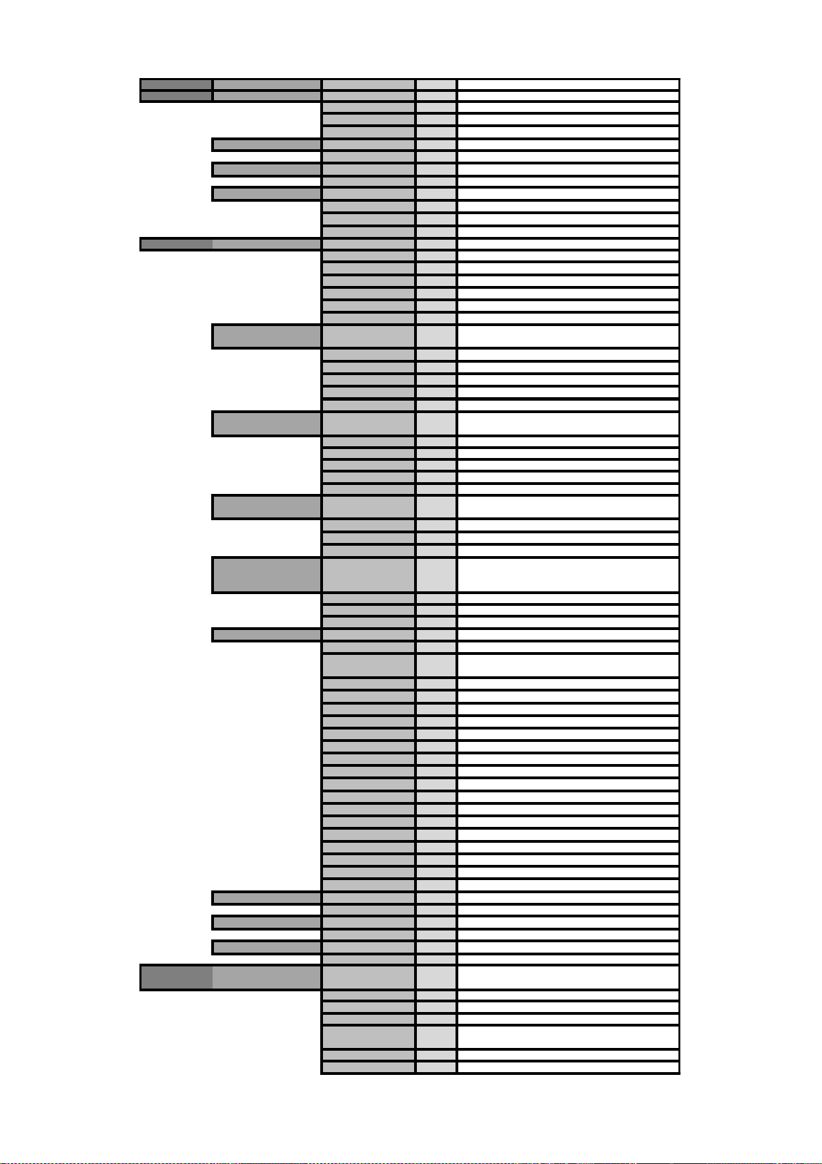
Level 1 Level 2 Level 3 Level 4 Explanati n
Configuration Data Source Choose out of the 3 possible data processing protocols.
Art-Net Art-Net protocol data input
sACN sACN protocol data input
DMX – IN Regular DMX signal input
Universe Insert universe number as needed
VALUE (0-255)
DMX address Sets DMX address for Omega Mk2 dimmer
VALUE (1-512)
Mode Set Omega Mk2 mode
Dimmer Dimmer mode
Relay Rela mode
Disabled No functionalit
Output curve
S-Curve
NA-Curve Subjectivel trul linear lighting output
Inv Square Finer control in bottom part of the curve
Linear Linear curve (voltage/ power level ratio is linear)
Soft linear
Square Provides finer control in top part of the curve
Preheat level
OFF No preheat. Use with caution!
0.02 2% preheat
0.04 4% preheat
0.06 6% preheat
0.08 8% preheat
Soft-start time
OFF
50 ms
100 ms
150 ms
200 ms
On source loss action
Hold output Holds latest DMX output
Blackout No DMX output- blackout
Recall scene Recalls scene recorded manuall
Source loss timeout
0 sec
10 sec
30 sec
Record scene Submenu for custom scene recording
Cancel Return to previous menu
Fade time
00 second fade time
11 second fade time
22 second fade time
33 second fade time
Save
Channel 1 intensity 0-255 Sets channel output intensit level
Channel 2 intensity 0-255 Sets channel output intensit level
Channel 3 intensity 0-255 Sets channel output intensit level
Channel 4 intensity 0-255 Sets channel output intensit level
Channel 5 intensity 0-255 Sets channel output intensit level
Channel 6 intensity 0-255 Sets channel output intensit level
Channel 7 intensity 0-255 Sets channel output intensit level
Channel 8 intensity 0-255 Sets channel output intensit level
Channel 9 intensity 0-255 Sets channel output intensit level
Channel 10 intensity 0-255 Sets channel output intensit level
Channel 11 intensity 0-255 Sets channel output intensit level
Channel 12 intensity 0-255 Sets channel output intensit level
Device ID Set custom Device ID label
Device ID label
IP address Set custom IP address
VALUE
Subnet mask Set custom submask network
VALUE
Defaults Touchscreen calibration
Reset
Confirm
Retreat
Factory defaults
Confirm
Retreat
Determines the preheat level provided to all dimmer
channels
This setting determines time needed for dimmer
output to achieve DMX value changes
Determines what action will be taken when data
source is lost
When the main source is lost, this determines how
long will the device wait for taking on source loss
action
Set the fade time (how long will the fade be when
source is lost)
Setting to use when the touchscreen calibration is
needed.
This setting will restore factor defaults (will reset
ALL settings to device default)

OMEGA MK2 MENU MAP
CONFIGURATION USING RESISTIVE LCD TOUCHSCREEN
OctoScene Mk2 can be configured locally on device by using control panel
buttons or remotely through Ethernet port by accessing built-in eb page ith
WEB bro ser.
Navigation trough menus is done using resistive LCD touch screen.
When device is turned on, it sho s this screen as a loading screen:
At this point, if pressed any here on the screen, a touch screen calibration
screen ill appear.
- 5 -

OMEGA MK2 HOME SCREEN
At the home screen you can see:
Overall inf rmati n ab ut dimmer:
ID: (the assigned name)
S urce: current signal source + DMX rate (Hz)
IP: assigned IP address
L1, L2, L3, N: voltage for phases
F: voltage frequency;
Fan: current fan speed;
T: current temperature of the dimmer
Status f r 12 channels:
Green bar- there is incoming DMX signal (the height of the green bar determines DMX sig-
nal level input value level)
N l ad – there is no incoming DMX signal.
Fuse! - the fuse s itch of the current channel is turned off.
- 6 -

INDIVIDUAL CHANNEL CONFIGURATION
Press on the middle square section ( here 12 channel status information is sho n) on the
home screen to enter individual channel configuration.
In this sub-menu it is possible to change settings for each dimmer channel separately.
It is p ssible t change these individual channel settings:
Channel name;
DMX address for each channel;
Mode for each channel;
Dimmer curve for each channel.
Phase and v ltage:
If there is no sufficient voltage or it is on critical level, then the status ill sho current
voltage and it ill be marked in red.
Status:
If one of the status items isn't at orking state, then this field ill sho “check”. At the
example above it can be seen that there is no load at the dimmer channel so the status is
currently at “check” state.
Fuse:
If the fuse state is ON, then the status indicator is GREEN.
If the fuse state is OFF, then the status indicator is RED.
L ad:
If the load state is “l ad”, then the status indicator is GREEN.
If the load state is “n l ad”, then the status indicator is RED.
Name:
Set custom name for the channel;
DMX:
Set DMX address for the channel;
M de:
Choose from dimmer mode, relay mode, or disabled.
- 7 -

Curve:
Choose out of 6 dimmer curves.
To return to main state- press “HOME” button.
EFFECTS:
By pressing “Take ver” button at home screen Omega Mk2 ill use input from this mode
for output.
Each of the presets (1-8) has pre- programmed effects available.
This mode is great for lamp testing purpose – you even don't need a lighting console to do
lamp tests anymore.
Virtual faders:
DIM- this fader option controls the output intensity level;
Speed- this fader option controls the speed of the effect chosen;
Offset- this fader option controls the offset bet een the chosen effect spikes.
To end “EFFECT” mode, enter the “Take ver” menu and select “OFF” option
“HOME” button returns user to the main menu (home) screen.
By pressing “HOME” button, Omega Mk2 ill return to the main (home) screen.
- 8 -

MANUAL FADE
It is possible to set intensity for all 12 dimmer channels in Omega Mk2 built in editor.
Fade time setting:
Fade time is the setting that determines ho long ill the fade be hen source is lost.
Example:
hen fade time is set at “3” (seconds), then hen Omega Mk2 loses input signal, the fade
bet een current controlling mode (DMX, Art-Net, sACN controls) and the backup mode ill
happen ithin 3 seconds.
hen fade time is set at “0” seconds, then
hen Omega Mk2 has lost its input signal, the fade bet een current controlling mode
(DMX, Art-Net, sACN controls) and the backup mode ill happen instantly and ill take no
fade time in bet een.
- 9 -

DEVICE CONFIGURATION
Press on the top square ( here ID, Source, IP, etc is sho n) on home page to enter the
configuration menu.
Device ID:
Here you can exchange the node name, replace the default name (Omega Mk2 is the de-
fault one) ith your desired name.
By pressing this button, a ne indo ill pop up:
Using this keyboard you can set the name to your desired name.
IP address:
By pressing the "IP setup" section, a ne indo ill pop up.
Here you can set the IP address for the Omega Mk2 dimmer.
- 10 -

Subnet mask:
By pressing the "Subnet mask" section, a ne indo s ill pop up.
Here you can set the subnet mask of the Omega Mk2.
To exchange assigned subnet (sub net ork) mask, replace the current net ork subnet
mask to your desired mask.
PROTOCOL SETUP:
By pressing the "Pr t c l" section, a ne indo ill pop up.
Besides the industries standart DMX controlling option, you can select out of 2 "DMX over
Ethernet" protocols: Art-Net and sACN (e1.31).
What is rt-Net and what is s CN?
Art-Net is an Ethernet protocol based on the TCP/IP protocol suite. Its
purpose is to allow trans er o large amounts o DMX512 data over a wide area
using standard networking technology
Streaming ACN (sACN) is a protocol to e iciently transport DMX universes
over the network. It is comparable to ArtNET in many aspects. One nice thing
is the multicast option allowing very easy con iguration. sACN is a popular
protocol to control large number o RGB LEDs.
- 11 -

So both of them are Ethernet protocols made to transport DMX universes over the
net ork, ith a fe minor differences.
When using the sACN protocol, the universe 0 is not allo ed to be used.
The system ill sho a arning sign if the universe 0 + sACN protocol has been chosen.
On s urce l ss:
By pressing the "On s urce l ss" section, a ne indo ill pop up.
When "H ld values" setting is chosen, after source loss there is no action at all, old data
remains in output
When "Black ut" setting is chosen, after DMX source loss the last value ill not be held
and there ill be a "blackout" (after delay, drop all DMX channels to 0).
When "Recall Scene" setting is chosen, after source loss the
S urce l ss time ut:
By pressing the "S urce l ss time ut" section, a ne indo ill pop up.
Here you can set the source loss timeout value. This setting ill change the time after
hich the Omega Mk2 ill start the blackout or stop DMX output on source loss.
You can put a value from 5 to 120, hich means from 5 to 120 seconds.
- 12 -

DEFAULTS:
T uch screen calibrati n ill open touch screen calibration menu.
Fact ry defaults ill reset all settings and restart the system.
After pressing reset buttons, there ill be a ne confirmation indo :
Where press "OK" to confirm your choice or "X" to retreat.
- 13 -

Universe:
Here you can assign the universe for Omega Mk2.
By pressing this section, a ne indo ill pop up
It is possible to set the universe from 0 to 255.
DMX address:
Here you can assign the DMX address for Omega Mk2.
By pressing this section, a ne indo ill pop up
It is possible to set the universe from 1 to 501 (the unit occupies 12 DMX channels as it is
12 channel dimmer).
- 14 -

M de:
It is possible to select out of 3 main modes:
Dimmer- regular dimmer mode ith all capabilities of the device;
Relay- relay mode
When relay mode is selected, lamps ill have 2 statuses- ON or OFF.
When DMX value for channel is 50% or belo - connected lighting fixtures ill be at OFF
position.
When DMX value for channel is 50% or above- connected lighting fixtures ill be at full ON
position.
Disabled- no lighting output, only stand-alone mode could be used to achieve lighting out-
put.
Output curve:
“The design o most analogue dimmers meant that the output o the dimmer was not directly
proportional to the input. Instead, as the operator brought up a ader, the dimmer would dim slowly at
irst, then quickly in the middle, then slowly at the top. The shape o the curve resembled that o the
third quarter o a sine wave. Di erent dimmers produced di erent dimmer curves, and di erent
applications typically demanded di erent responses.
Television o ten uses a "square law" curve, providing iner control in top part o the curve, essential to
allow accurate trimming o the colour temperature o lighting. Theatrical dimmers tend to use a so ter
"S" or linear curve. Digital dimmers can be made to have whatever curve the manu acturer desires; they
may have a choice between a linear relationship and selection o di erent curves, so that they can be
matched with older analogue dimmers. Sophisticated systems provide user-programmable or
nonstandard curves, and a common use o a nonstandard curve is to turn a dimmer into a "non-dim",
switching on at a user de ined control level.”
Source: https://en.wikipedia.org/wiki/Dimmer#Dimming_curves
- 15 -

S- Curve - provides a finer control at lo er and higher levels hile being more coarse at
medium levels. This dimming curve best emulates a typical incandescent lamp's dimming
abilities. This curve is often considered the most natural dimming curve.
NA- Curve - hen using the NA-Curve, subjectively (in our vision) this curve is truly linear
hen conventional tungsten lights are used.
Inv Square - provides a finer control at high levels and coarser at lo levels. Useful hen
not dimming all the ay out or hen less lo level control is desired (snap on/off).
Linear - The linear curve matches the control input percentage to Root Mean Squared
(RMS) voltage output. Each percent increase in control level increases dimmer voltage
output by the same amount
S ft Linear - based on linear curve principle but ith a small addition from S-Curve –
provides finer control at lo er and higher levels.
Square - (Square law curve ) - At lo control levels, much of traditional incandescent
fixture’s light output is in the invisible infrared spectrum. This results in poor visible
response to lo control levels. A square la curve applies a multiple derived from the
square root of the control level ( ith full output equal to 1.00) to increase voltage response
at lo control levels to compensate for the infrared loss.
Example graph f h w different curves interact with utput v ltage / level (in %).
- 16 -

Preheat level:
This setting determines the actual intensity the lights ill be on hat intensity at idle status.
The preheat value must be chosen and analyzed by eye- hen the bulb is too bright at idle
mode, turn do n the preheat level to lo er.
S ft start time:
This setting determines the time needed for intensity changes to kick in.
Example:
Currently the DMX level for channel is set at 0% (0). When the DMX value is increased to
100% (255), light output ill not change instantly but ill cross fade at the soft-start time
chosen.
Soft start usually makes lamp life longer but may be not needed for some fixture / lamp
types.
- 17 -

T uch screen calibrati n:
There are 2 possible ays to open the touch screen calibration menu:
1) When device is turning on, press any here on the "Omega Mk2" illustration;
2) Open device defaults settings here "touchscreen calibration" reset setting can be
seen.
No you have to press the red dots in order to calibrate the touch screen.
There ill be 4 dots in total- each dot in all 4 corners.
Press each of the red dot precisely as possible to ensure correct calibration.
- 18 -

Set up dimmer using built-in web-server:
Type current Omega MK2 IP address into your favorite eb-bro ser (Microsoft Edge,
Google Chrome, Mozilla Firefox, etc).
Omega Mk2 eb-server ill open.
Here it is possible to set almost all the same settings as via touchscreen.
This option might be useful if the controlling is done ith Art-Net / sACN and the dimmer it-
self is not directly accessible.
Upgrading the firmware.
Firm are upgrade is possible only by using Omega Mk2 built-in eb-server.
To get the ne est firm are, please, contact info@na.lv ith subject “Omega Mk2 firm are
upgrade” and e ill send you up to date firm are as soon as possible.
- 19 -
Table of contents