Igloo COSTA User manual

1
pl
Instrukcja obsługi Costawww.igloo.pl
Spis treści Spis rysunków
Spis tabel
Rys.1 Budowa urządzenia 2
Rys.2 Usuwanie podestu drewnianego 3
Rys.3 Mocowanie haka w stelażu 3
Rys.4 Zespółpółki siatkowej 3
Rys.5 Zespółpółki metalowej (opcja) 4
Rys.6 Listwa z hakami mięsnymi (opcja) 4
Rys.7 Kosze na owoce i warzywa (opcja) 4
Rys.8 Panel sterowania 4
Rys.9 Wymiana świetlówek 6
Rys.10 Tabliczka znamionowa 7
Rys.11 Panel termostatu „Igloo” 8
Rys.12 Panel termostatu „Carel” 9
1. ROZŁADUNEK 1
2. CHARAKTERYSTYKA WYROBU 1
2.1. Przeznaczenie 1
2.2. Opis urządzenia 1
2.3. Dane techniczne 2
3. PRZYGOTOWANIE URZĄDZENIA DO EKSPLOATACJI 3
3.1. Wymagania dotyczące miejsca instalacji 3
3.2. Podłączenie i uruchomienie 3
4. EKSPLOATACJA 4
4.1. Regulacja temperatury 5
5. KONSERWACJA 5
5.1. Czyszczenie i konserwacja 5
6. SERWIS 6
6.1. Identyfikacja i naprawa usterek 6
6.2. Serwis 7
7. OBSŁUGA TERMOSTATU 8
7.1. Termostat „IGLOO” 8
7.2. Termostat „CAREL” 9 Tabela 1 Dane techniczne 2
1. ROZŁADUNEK
Urządzenie powinno byćtransportowane w pozycji pionowej, odpowiednio zabezpieczone i spakowane. Producent wysy-
ła urządzenie na specjalnym podeście drewnianym, zabezpieczone tekturowymi kątownikami oraz folią.
2. CHARAKTERYSTYKA WYROBU
2.1. Przeznaczenie
„COSTA” jest uniwersalnym urządzeniem chłodniczym przeznaczonym do przechowywania i eksponowania szerokiego
asortymentu artykułów spożywczych uprzednio wychłodzonych do temperatury przechowywania. Gwarantowana tempe-
ratura wewnątrz regału +2ºC/+8ºC przy temperaturze otoczenia +15ºC/+25ºC i wilgotności wzgl. powietrza do 60%.
2.2. Opis urządzenia
Regały „COSTA” posiadająchłodzenie dynamiczne. Wszystkie typy wyposażone sąw elektroniczny termostat i odszra-
nianie automatyczne. Przystosowane sądo łączenia w ciągi w wersji na agregat centralny (mod/C). Regały wyposażone
sąw 5 półek ekspozycyjnych siatkowych, posiadających możliwość zmiany wysokości oraz kąta zawieszenia. W opcji
można zamówićpółki pełne z blachy, haki mięsne lub kosze na warzywa i owoce.
Wnętrze regału może byćpodświetlane świetlówkami umieszczonymi pionowo w bocznych częściach regału. Regał
posiada drzwi przeszklone, przesuwne. Urządzenia „IGLOO” wykonywane sąw/g nowoczesnych technologii i posiadają
wymagane prawem certyfikaty.
Tym znakiem oznaczone sąinformacje o szczególnym znaczeniu dla bezpieczeństwa użytkownika
oraz do prawidłowej eksploatacji urządzenia
Instrukcja obsługi COSTA
pl

2
pl
Instrukcja obsługi Costa www.igloo.pl
2.3. Dane techniczne
Tabela 1 Dane techniczne
Typ
urządzenia
„COSTA”
Napięcie
znamion.
[V/Hz]
Prąd
znamion.
[A]
Moc
znamion.
oświetl. [W]
Zużycie
energii elektr.
[kWh/24h]
Zapotrzeb.
na moc
chłodniczą
[W/mb]
Max
obciąż.
półki
[kg/mb]
Waga
urz. [kg]
1.3-mod/C 230/50 0,5 72 * 1,6 600 50 195
2.5-mod/C 230/50 0,9 108 * 2,7 600 50 350
Rys.1 Budowa urządzenia
1 – Podświetlany panel górny
2 - Panel sterowania wewnątrz regału (regulator tempe-
ratury / wyłączniki)
3 – Półki siatkowe
4 – Uchwyt drzwi
5 – Drzwi przesuwne, przeszklone
6 - Odbojnica frontowa
7 - Podstawa regału
8 - Podest drewniany zakładany do transportu urzą-
dzenia
9 – Bok izolowany z blachy, pełny
10 – Tabliczka znamionowa
11 – Sito regału (NIE BLOKOWAĆOTWORÓW wenty-
lacyjnych zapewniających cyrkulacjęschłodzonego
powietrza!!!)
12 - Panel frontowy
13 - Nóżki służące do wypoziomowania urządzenia
1
2
3
4
5
6
7
8
9
12
7
5
13
11
NS-069XXX
MASAxxx
NAPIECIEZNAM.xxx
MOCZN.OŒW.xxx
MOCGRZA£EK.xxx
NAPIECIEZNAM.xxx
KLASAURZADZ.xxx
TypNAZWAURZ¥DZENIA
PR¥DZNAM.xxx
10
3
* Moc znamionowa oświetlenia w urządzeniach z podświetleniami bocznymi jest większa niżpodana w tabeli o
116W !

3
pl
Instrukcja obsługi Costawww.igloo.pl
3. PRZYGOTOWANIE URZĄDZENIA DO EKSPLOATACJI
3.1. Wymagania dotyczące miejsca instalacji
• Sprawdź, czy przekrój przewodów zasilających jest odpowiedni dla poboru prądu instalowanego urządzenia
• Zabrania siępodłączania urządzenia przez przewody przedłużające lub rozdzielacze
• Urządzenie należy podłączyćdo oddzielnego, prawidłowo wykonanego obwodu elektrycznego z gniazdem wtykowym
z kołkiem ochronnym (w/g PBUE)
Uruchomienie urządzenia, może nastąpićtylko po potwierdzeniu skuteczności ochrony przeciwpo-
rażeniowej wynikami z pomiarów, przeprowadzonymi zgodnie z obowiązującymi przepisami!
3.2. Podłączenie i uruchomienie
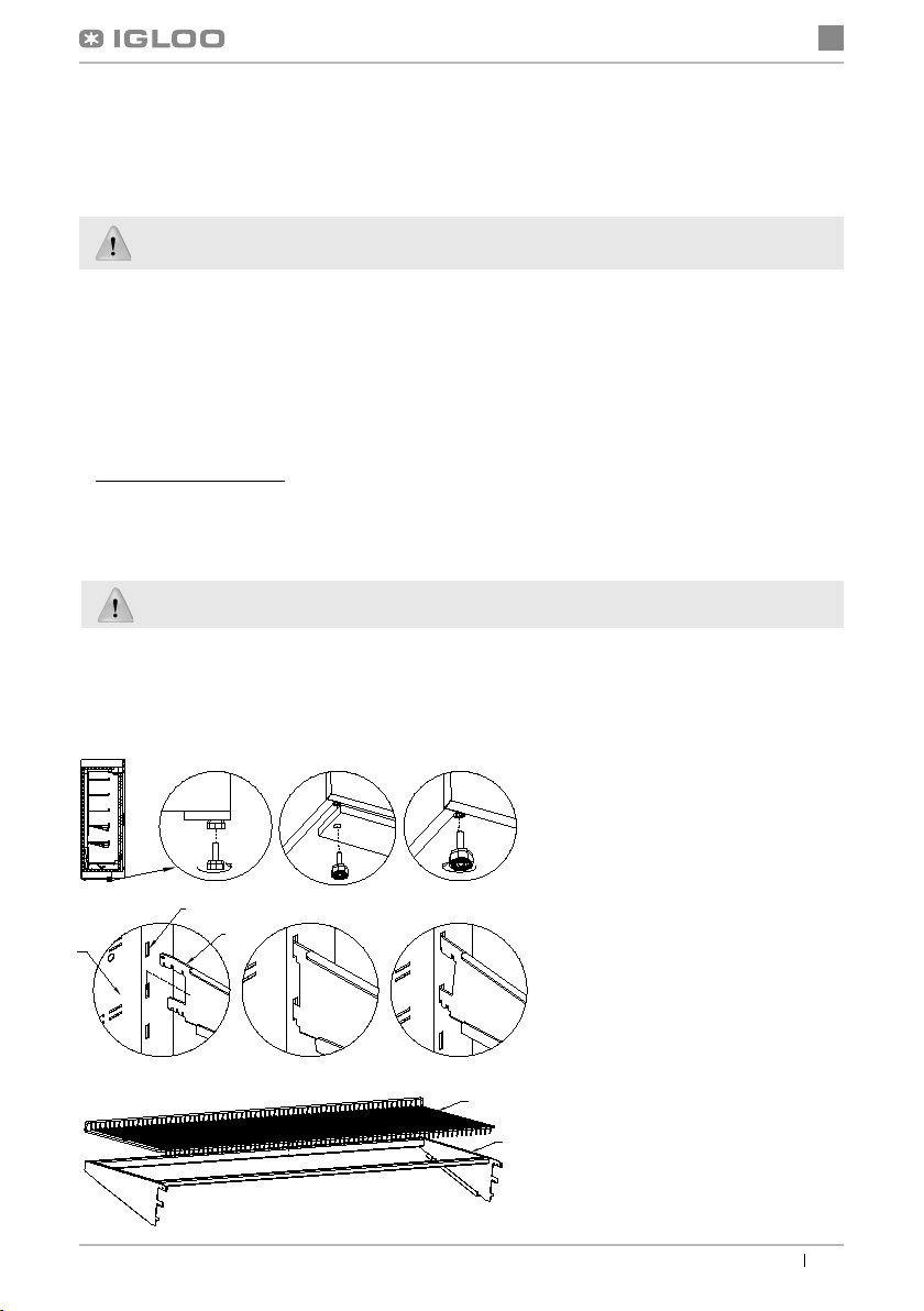
• Rozpakowaćurządzenie i usunąć drewniany podest znajdujący sięna podstawie Rys.2(str.3)
• Urządzenie ustawićna równym i dostatecznie twardym podłożu, a następnie wypoziomowaćje za pomocą
nóżek
• Ściągnąć folięochronnąz elementów urządzenia (m.in. z wnętrza urządzenia i odbojnicy frontowej)
• Jeżeli urządzenie trafido użytkownika częściowo zdemontowane dla zabezpieczenia w czasie transportu
należy wykonaćnastępujące operacje:
1. Zamontowaćzespółhaka w listwach stelaża Rys.3 (str.3)
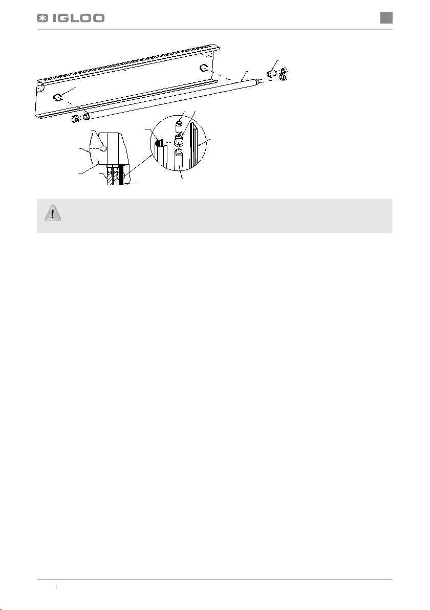
2. Pod dnem korpusu urządzenia (ok.110 mm od pleców regału, w części środkowej korpusu) znajduje sięspust
wody z odszraniania, z którego należy przewidziećodpływ wody do kratki ściekowej
• Pierwsze mycie urządzenia powinno byćwykonane po rozpakowaniu urządzenia i przed jego uruchomieniem. Urzą-
dzenie należy umyćwodąo temperaturze nieprzekraczającej 40ºC z dodatkiem neutralnych środków czyszczących.
Do mycia i czyszczenia urządzenia zabrania sięstosowania środków zawierających chlor i sód różnych odmian,
które niszcząwarstwęochronnąi elementy składowe urządzenia
!
Ewentualne pozostałości klejów czy silikonu
na elementach metalowych urządzenia usuwaćwyłącznie benzynąekstrakcyjną(nie dotyczy elementów z plastiku i
tworzyw sztucznych!). Nie wolno używaćinnych rozpuszczalników organicznych.
Podczas mycia urządzenia zabrania sięużywaćstrumienia wody. Urządzenie należy myć
przy użyciu wilgotnej ściereczki
• Umieścićwtyczkęprzewodu przyłączeniowego bezpośrednio w gnieździe wtykowym (zabrania siępodłącza-
nia urządzenia przez przewody przedłużające lub rozdzielacze!)
• Załączyćprzycisk wyłącznika głównego Rys.8/2 (str.4), co spowoduje załączenie regulatora temperatury, a
następnie agregatu urządzenia
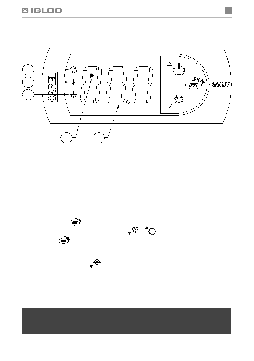
• Na panelu termostatu Rys.8/1 (str.4) ustawićtemperaturę(szczegóły obsługi na str.8 i 9)
• Załączyćprzycisk oświetlenia Rys.8/3 (str.4)
Rys.3 Mocowanie haka w stelażu
Rys.4 Zespółpółki siatkowej
Rys.2 Usuwanie podestu drewnianego
1 – Sito regału
2 – Stelażdo mocowania haków
3 – Hak (dostosowany do
trzystopniowej reg. kąta
zawieszenia)
1 – Półka siatkowa
2 – Zespółhaków wraz z profi-
lami (kontr. usztywniająca
półkę)
1 – Wykręcićnóżki z podestu
2 – Usunąć drewniany podest
3 – Wkręcićnóżki w nakrętki przy-
spawane do ramy urządzenia
1
2
3
123
1
2

4
pl
Instrukcja obsługi Costa www.igloo.pl
4. EKSPLOATACJA
Temperatura chłodzonej przestrzeni i cykl pracy agregatu mogąulegaćwahaniom. Zależą one od wielu czynników m.
in. od ilości i temperatury włożonych produktów oraz od temperatury otoczenia.
Urządzenie należy ustawićw miejscu suchym, nienasłonecznionym, dobrze wentylowanym, zapewniającym dobrą
wymianępowietrza (dystans pomiędzy ścianą, a urządzeniem min. 10 cm), z dala od źródełciepła i urządzeńwy-
muszających przepływ powietrza (wentylatory sufitowe i przenośne, grzejniki nadmuchowe). Urządzenie funkcjonuje
poprawnie w środowisku, w którym temperatura zawiera sięw odpowiedniej klasie klimatycznej podanej na tabliczce
znamionowej. Działanie urządzenia może ulec pogorszeniu, gdy przez dłuższy czas funkcjonowaćbędzie w tempera-
turze wyższej lub niższej w stosunku do podanego przedziału.
Rys.5 Zespółpółki metalowej (opcja)
1 – Hak pod półkę
2 – Element zabezpieczający półkęprzed
przesuwaniem
3 – Półka regału
4 – Kierownica schłodzonego powietrza
5 – Listwa cenowa półki
6 – Ogranicznik półek
Rys.8 Panel sterowania
1 – Panel termostatu (regulatora temperatury)
(szczegóły obsługi w Rozdziale nr 7 str.8 i 9)
2 - Wyłącznik główny (załącza/wyłącza agregat urzą-
dzenia)
3 - Wyłącznik oświetlenia
231
1
3
2
4
5
6
Rys.6 Listwa z hakami mięsnymi (opcja)
1 - Hak pod listwęz hakami mięsnymi
2 - Listwa pod haki mięsne
3 – Haki mięsne
13
2
Rys.7 Kosze na owoce i warzywa (opcja)
1 – Hak pod kosz
2 – Kosz na owoce i warzywa
3 – Profil stalowy zamknięty 20x20x2
łączący kosze
1
2
3

5
pl
Instrukcja obsługi Costawww.igloo.pl
Uwagi i wskazówki
• Należy prawidłowo wypoziomowaćregał, co zapobiegnie hałaśliwej pracy urządzenia i zapewni prawidło-
wy odpływ wody (kondensatu) podczas odszraniania
• Aby zapewnićżywności właściwe warunki przechowywania, nie wolno zapełniaćpółek całkowicie. Należy
zapewnićrównomierne obciążenie półek i nie przekraczaćich maksymalnego obciążenia
• Pierwsze zapełnienie przestrzeni chłodniczej należy dokonywaćpo uprzednim jej wychłodzeniu do tempe-
ratury pracy. Zasada ta powinna byćtakże przestrzegana po dłuższej przerwie w eksploatacji
• Nie blokowaćżadnych otworów wentylacyjnych, co mogłoby utrudnićcyrkulacjęschłodzonego powietrza
• Zabrania siędostawiania towaru bezpośrednio do sita (do pleców urządzenia)
• Wewnątrz komory do przechowywania produktów żywnościowych nie używaćprzyrządów elektrycznych
4.1. Regulacja temperatury
Obsługa termostatów (regulatorów temperatury) „Igloo” i „Carel” znajduje sięw rozdziale 7 (str. 8 lub 9)
Podstawowym zadaniem termostatu jest sterowanie agregatem chłodniczym tak, aby uzyskaćzadanątempera-
turęwewnątrz urządzenia i utrzymywaćjąw określonych przedziałach. Wszystkie nastawy regulatora temperatu-
ry konieczne do normalnego funkcjonowania urządzenia sąwprowadzone przez producenta. Użytkownik przed
pierwszym uruchomieniem urządzenia powinien sprawdzići ewentualnie ustawićna panelu termostatu żądaną
temperaturęwewnątrz urządzenia.
Cyfrowy wyświetlacz – wyświetla bieżącątemperaturęwewnątrz urządzenia
Wszelka ingerencja w ustawienia fabryczne termostatu powoduje utratęgwarancji!
5. KONSERWACJA
5.1. Czyszczenie i konserwacja
Wszelkie czynności konserwacyjne należy prowadzićpo odłączeniu urządzenia od napięcia!
Chronićprzed uszkodzeniem lub zalaniem wodąinstalacjęelektryczną
Podczas mycia urządzenia zabrania sięużywaćstrumienia wody. Urządzenie należy myć
przy użyciu wilgotnej ściereczki
Nie należy stosowaćżadnych ostrych przedmiotów celem usuwania zabrudzeń!
Elementy urządzenia mogąkorodowaćprzy niewłaściwym użytkowaniu i konserwacji.
Należy przestrzegaćzasad:
• Nie dopuszczaćdo kontaktu powierzchni urządzenia z środkami zawierającymi chlor i/lub sodę
w różnych odmianach, które niszcząich warstwęochronnąi elementy składowe urządzenia
(dotyczy równieżróżnych gatunków stali nierdzewnej)
Raz na miesiąc zaleca sięprzerwęw eksploatacji urządzenia celem oczyszczenia jego wnętrza i natural-
nego odszronienia parownika.
W celu przyspieszenia procesu odszraniania nie posługiwaćsięśrodkami mechanicznymi!

6
pl
Instrukcja obsługi Costa www.igloo.pl
9
3
7
2
1
3
4
5
5
6
7
89
Rys.9 Wymiana świetlówek
6. SERWIS
6.1. Identyfikacja i naprawa usterek
W przypadku wystąpienia jakichkolwiek trudności podczas uruchamiania urządzenia lub podczas jego eksploatacji należy
powrócićdo tych rozdziałów instrukcji obsługi, które wyjaśniająwykonywanąoperację. Ma to na celu upewnienie się, czy
urządzenie jest prawidłowo obsługiwane. Jeżeli trudności występująnadal, poniższe wskazówki pomogąw ich usunięciu.
Urządzenie nie pracuje...- Upewnićsię, czy:
• Urządzenie jest podłączone do sieci prądu elektrycznego
• Napięcie i częstotliwość w sieci sąodpowiednie z tymi, jakie zaleca producent (patrz tabliczka znamionowa)
• Włączony jest wyłącznik główny
• Termostat jest załączony (Dotyczy term. Igloo – Jeśli na wyświetlaczu wyświetlająsięjedynie dwie kropki – włącz
termostat)
Urządzenie pracuje, oświetlenie nie świeci...- Upewnićsię, czy:
• Wyłącznik oświetlenia jest w pozycji załączonej
• Świetlówka lub zapłonnik w urządzeniu nie uległy spaleniu
Urządzenie nie osiąga odpowiedniej temperatury, oświetlenie świeci...- Upewnićsię, czy:
• Wyłącznik główny jest w pozycji załączonej
• Nastawa temperatury na termostacie jest odpowiednio ustawiona
• Termostacie działa poprawnie
• Temperatura otoczenia nie jest wyższa niż25ºC
• Minęło wystarczająco dużo czasu dla schłodzenia produktów
• Otwory wentylacyjne urządzenia nie sązablokowane
(Dotyczy term. „IGLOO”) Termostat wyświetla C0 lub C1 lub C2 zamiast temperatury:
Sytuacja taka ma miejsce, jeżeli zostałuszkodzony jeden z czujników regulatora wówczas mogąpojawićsię
następujące komunikaty:
• C0 –uszkodzenie czujnika temperatury wewnątrz komory –wezwaćautoryzowany serwis
• C1 –uszkodzenie czujnika parownika - wezwaćautoryz. serwis
• C2 –uszkodzenie czujnika alarmu skraplacza (lub uszkodzenie drugiego czujnika parownika) – wezwaćautoryzo-
wany serwis
Podczas czynności konserwujących należy uważać, aby nie uszkodzićtabliczki znamionowej
urządzenia Rys.10 (str.7), która zawiera istotne informacje dla serwisantów oraz firm zajmujących
sięusuwaniem odpadów.
1 – Płyta pleksi panelu górnego
2 – Uchwyty mocujące płytępleksi
3 - Uchwyt świetlówki (panelu górnego)
4 – Drzwi przeszklone
5 – Profil PCV (podświetlenie boczne)
6 – Przeźroczysta oprawa świetlówki (klosz)
7 - Świetlówka
8 – Oprawa świetlówki
9 – Zapłonnik świetlówki

7
pl
Instrukcja obsługi Costawww.igloo.pl
(Dotyczy term. „CAREL”) Termostat wyświetla E0 lub E1 lub L0 lub HI lub EE lub Ed lub DF zamiast tempe-
ratury:
• E0 -uszkodzenie czujnika temperatury wewnątrz komory- wezwaćautoryzowany serwis
• E1 -uszkodzenie czujnika parownika - wezwaćautoryz. serwis
• L0 –alarm niskiej temperatury (niższej niżzadany zakres wewnątrz urządzenia) - wezwaćautoryzowany serwis
• HI - alarm wysokiej temperatury - wezwaćautoryzowany serwis
• EE -błąd wewnętrzny regulatora - wezwaćautoryzowany serwis
• Ed – przekroczenie max. czasu odszraniania
• DF – odszranianie w toku (to nie jest sygnałalarmowy)
Osadzanie siępary wodnej na szybach urządzenia przy dużej wilgotności względnej powietrza
powyżej 60% jest zjawiskiem naturalnym i nie wymaga wzywania serwisu!
6.2. Serwis
Jeśli po sprawdzeniu punktów opisanych w rozdziale 6.1 „Identyfikacja i naprawa usterek” urządzenie nadal nie
działa prawidłowo, należy skontaktowaćsięz Serwisem Technicznym firmy Igloo, podając dane z tabliczki zna-
mionowej Rys.10 (str.7)
• Numer seryjny (NS)
• Datęprodukcji
• Typ (nazwa urządzenia)
oraz
• Datęzakupu urządzenia
• Opis problemu
• Dokładny adres i numer telefonu
wraz z numerem kierunkowym do Państwa
Tabliczka znamionowa znajduje sięwewnątrz
urządzenia, na sicie w prawym, górnym jego rogu
Powyższy rysunek przedstawia poglądową
tabliczkęznamionową, a dane w niej zawarte
sądanymi przykładowymi nieodnoszącymi się
do „COSTY”!
Rys.10 Tabliczka znamionowa

8
pl
Instrukcja obsługi Costa www.igloo.pl
Sprawdzanie nastawionej temperatury (wewnątrz urządzenia) – Naciskając przycisk „▲” lub „▼” jeden raz możemy
sprawdzićnastawionątemperaturę. Na wyświetlaczu pojawia sięnastawiona temperatura, przy której świeci sięczerwo-
na mrugająca kropka (dioda). Wyjście z podglądu następuje automatycznie po ok. 3 sekundach.
Obniżenie (lub podwyższenie) temperatury – naciskamy przycisk „▼” (lub „▲”) i na panelu pojawi sięustawiona tempe-
ratura. Naciskając przycisk „▼” obniżamy temperaturędo żądanej wartości. Wyjście z funkcji następuje automatycznie
po ok. 3 sek.
Ręczne odszranianie –przycisk nr 2 pozwala na włączenie cyklu odszraniania w dowolnym momencie pracy urządzenia
(niezależnie od funkcji automatycznego odszraniania); przycisk nie działa, gdy temperatura jest wyższa niżtemperatura
końca odszraniania
Zaleca się, aby użytkownik załączał/wyłączałagregat korzystając jedynie z wyłącznika głównego urzą-
dzenia, a nie z przycisku bezpośrednio na panelu termostatu. Załączenie wyłącznika głównego automa-
tycznie załącza termostat!
* Więcej na stronie www.igloo.pl
1 – Przycisk włącz/wyłącz chłodzenie
2 – Przycisk ręcznego odszraniania
3 – Kontrolka pracy agregatu i odszraniania
4 - Przycisk podglądu temp. na czujniku odszraniania
5 – Przycisk zmiany temp. do góry
6 – Przycisk zmiany temp. w dół
7. OBSŁUGA TERMOSTATU
7.1. Termostat „IGLOO”
Rys.11 Panel termostatu "Igloo"

9
pl
Instrukcja obsługi Costawww.igloo.pl
1
2
3
5
4
CO OZNACZAJĄDIODY NA WYŚWIETLACZU
Zapalona dioda 1 - Sprężarka: symbol jest widoczny, gdy sprężarka pracuje. Miga, gdy start sprężarki jest opóźniony
przez proceduręochronną. Miga w cyklu: dwa mignięcia – przerwa, gdy uruchomiony jest tryb pracy ciągłej.
Zapalona dioda 2 - Wentylator: symbol jest widoczny, gdy włączone sąwentylatory parownika. Miga, gdy start wentyla-
torów jest opóźniony poprzez zewnętrzne wyłączenie lub, podczas gdy inna procedura jest w toku.
Zapalona dioda 3 - Odszranianie: symbol jest widoczny, gdy włączona jest funkcja odszraniania. Miga, gdy start odszra-
niania jest opóźniony poprzez zewnętrzne wyłączenie lub podczas, gdy inna procedura jest w toku.
Zapalona dioda 4 - Alarm: symbol jest widoczny, gdy aktywny jest alarm
Zapalona dioda 5 – wyświetlana bieżąca temperatura wewnątrz urządzenia (po przecinku wyświetlane miejsca dzie-
siętne)
NASTAWA ŻĄDANEJ TEMPERATURY
- naciśnij przez 1 sekundę: wartość wodząca pojawi sięna ekranie;
- zwiększ lub zmniejsz wartość wodzącąużywając klawiszy i , ażosiągniesz pożądanąwartość;
- naciśnij ponownie w celu potwierdzenia nowej wartości punktu nastawy;
RĘCZNE WYMUSZENIE CYKLU ODSZRANIANIA
Odszranianie realizowane jest w sposób automatyczny. Można jednak w dowolnej chwili wymusićodszranianie poprzez
naciśnięcie i przytrzymanie przycisku przez minimum 5 sekund. Podczas ręcznego odszraniania miga dioda 1.
* Więcej na stronie www.alfaco.pl
7.2. Termostat „CAREL”
Rys.12 Panel termostatu "Carel"
UWAGA: W PRZYPADKU NIE ZASTOSOWANIA SIĘDO ZASAD ZAWARTYCH W NINIEJSZEJ INSTRUKCJI DO-
TYCZĄCYCH PODŁĄCZENIA I EKSPLOATACJI URZĄDZENIA, PRODUCENT ZASTRZEGA SOBIE PRAWO OD-
STĄPIENIA OD OBOWIĄZKÓW GWARANTA!!!
Informacje zawarte w tym dokumencie mogąbyćzmienione przez „IGLOO” bez powiadamiania użytkownika.
Kopiowanie niniejszej instrukcji bez zgody producenta jest zabronione.
Zdjęcia oraz rysunki mającharakter poglądowy i mogąsięróżnićod zakupionego urządzenia.

en
10 User manual Costa www.igloo.pl
Fig.1 Construction of the device 11
Fig.2 Removing the wooden platform 12
Fig.3 Mounting the hook in the frame 12
Fig.4 Grid shelf system 12
Fig.5 Metal shelf system (option) 13
Fig.6 Meat hook strip (option) 13
Fig.7 Fruit and vegetable baskets (option) 13
Fig.8 Control panel 13
Fig.9 Changing the fluorescent lamp 15
Fig.10 Data plate 16
Fig.11 „Igloo” thermostat control panel 17
Fig.12 „Carel” thermostat control panel 18
1. UNLOADING
The device should be transported in vertical position, and it should be properly secured and packed. The manufacturer
ships the device on a special wooden platform, secured with cardboard angle sections and foil.
2. PROPERTIES OF THE DEVICE
2.1. Purpose
“COSTA” is a universal cooling device used to store and display a wide assortment of grocery products previously cooled
to storing temperature. Guaranteed temperature within the refrigerating rack ranges between +2ºC and +8ºC with ambient
temperature ranging between +15ºC and +25ºC and relative air humidity of up to 60%.
2.2. Description of the device
“COSTA” racks are equipped with dynamic cooling. All types of devices are equipped with electronic thermostat and
automatic defrosting. They can be connected in sequences in the version on the central aggregate (mod/C). Racks are
equipped with 5 grid display shelves, with regulated height and fixing angle. It is also possible to order full shelves made
of metal plate, meat hooks or fruit and vegetable baskets.
Interior of the rack may be illuminated with fluorescent lamps placed vertically in side parts of the refrigerating rack. The
rack is equipped with glazed, sliding doors. Our devices are made according to modern technologies and have all certi-
ficates required by law.
This sign signifies information of particular meaning for user security and for proper device
exploitation.
Contents List of Figures
List of tables
Table 1 Technical data 11
User manual
1. UNLOADING 10
2. PROPERTIES OF THE DEVICE 10
2.1. Purpose 10
2.2. Description of the device 10
2.3. Technical data 11
3. PREPARING THE DEVICE FOR EXPLOITATION 12
3.1. Requirements concerning the place of installation 12
3.2. Connection and actuation 12
4. EXPLOITATION 13
4.1. Temperature regulation 14
5. MAINTENANCE 14
5.1. Cleaning and maintenance 14
6. SERVICE 15
6.1. Fault identification and repair 15
6.2. Service 16
7. THERMOSTAT SERVICE 17
7.1. “IGLOO” thermostat 17
7.2. “CAREL” thermostat 18
en
COSTA

en
11
User manual Costawww.igloo.pl
2.3. Technical data
Table 1 Technical data
Type of the
device„CO-
STA”
Rated
voltage
[V/Hz]
Rated
current
[A]
Rated ligh-
ting power
[W]
Electric
energy
consumption
[kWh/24h]
Cooling power
requirement
[W/mb]
Max. shelf
load
[kg/mb]
Weight
of the
device
[kg]
1.3-mod/C 230/50 0,5 72 * 1,6 600 50 195
2.5-mod/C 230/50 0,9 108 * 2,7 600 50 350
Fig.1 - Construction of the device
1 – Illuminated upper panel.
2 – Control panel inside the device (temperature
regulator /switches)
3 – Grid shelves
4 – Door grip
5 – Glazed, sliding doors
6 – Front fender beam
7 – Basis of the rack
8 – Wooden platform mounted for transportation
9 – Insulated, full metal plate block
10 – Data plate
11 – Screen of the rack (DO NOT BLOCK ventilation
holes ensuring circulation of the cooled air!!!)
12 – Front panel
13 – Feet used for levelling the device
1
2
3
4
5
6
7
8
9
12
7
5
13
11
NS-069XXX
MASAxxx
NAPIECIEZNAM.xxx
MOCZN.OŒW.xxx
MOCGRZA£EK.xxx
NAPIECIEZNAM.xxx
KLASAURZADZ.xxx
TypNAZWAURZ¥DZENIA
PR¥DZNAM.xxx
10
3
* The rated lighting power in devices with side illuminations is 116W greater than the one stated in table!

en
12 User manual Costa www.igloo.pl
3. PREPARING THE DEVICE FOR EXPLOITATION
3.1. Requirements concerning the place of installation
• Verify whether the cross-section of feeding conduits is proper for the power consumption of the installed device
• It is forbidden to connect the device by means of extension cords or dividers
• The device should be connected to the separate, properly made electric circuit with plug-in socket
with protecting pin (according to PBUE /Regulations concerning Electric Equipment Construction/)
The device may be actuated solely after confirmation of the fire protection efficiency with results of
measures performed according to binding regulations!
3.2. Connection and actuation
• Unpack the device and remove the wooden platform from the basis Fig.2 (p.12)
• Place the display cabinet on an even basis, which is hard enough, and then level it with feet.
• Remove the protecting foil from elements of the device (f. ex.: from the inside of the device and the front fender beam)
• If the user shall obtain a device partially disassembled to secure it during transportation, perform the following operations:
1. Mount the hook system on rack frames Fig. 3 (p.12)
2. Defrosted water outlet is located under the body of the device (about 110 mm from the back of the rack, in the middle part
of the body), and water outlet should be connected with sewage grid.
• Place the plug of the connecting cable directly in plug-in socket (it is forbidden to connect the device by means
of extension cords or dividers!)
• Turn the main switch on Fig. 8/2 (p.13), which will activate the thermostat, and then the aggregate of the device.
• Set the temperature on the thermostat panel Fig.8/1 (p.13) (service details on p.17 or 18)
• Turn on the lighting switch Fig. 8/3 (p.13)
Fig.3 Mounting the hook
in the rack frame
Fig.4 Grid shelf system
Fig.2 Removing the wooden platform
1 – Screen of the rack
2 – Frame for mounting the hooks
3 – Hook (adjusted to three-degree regula-
tion of the suspension angle)
1 – Grid shelf
2 - Hook system with profiles (shelf
tightening construction)
1 - Unscrew the feet from the platform
2 – Remove the wooden platform
3 – Screw the feet in nuts welded to the
frame of the device
1
2
3
123
1
2
• The first cleaning of the device should be provide right after unpacking, and before turning it on. The unit should
be cleaned with water at a temperature not exceeding 40°C with a neutral detergent. For washing and cleaning
the equipment it is prohibited to use products containing chlorine and sodium varieties, which destroy the protecti-
ve layer and components of the device! Any residue of adhesives or silicone on metal elements should be remo-
ved only with extraction naphtha (not applicable to items made of plastic !). Do not use other organic solvents.
When cleaning the unit is prohibited to use water jet. The unit should be cleaned with a wet rag.

en
13
User manual Costawww.igloo.pl
4. EXPLOITATION
Temperature of cooled space and operating cycle of the aggregate may vary. It depends on numerous factors, such as
amount and temperature of products placed in the device and temperature of the surroundings.
The device should be placed in a dry place, not insolated and well ventilated, ensuring proper air circulation (min. 10
cm distance between the wall and the device), far from sources of heat and devices forcing the air circulation (roof ad
mobile ventilators, blowing heaters). The device operates properly in an environment, where temperature falls within
proper climate class stated on the data plate. The operation of the device may worsen, when it will operate in tempera-
ture higher or lower than the one determined in the stated temperature range.
Fig.5 Metal shelf system (option)
1 – Hook under the shelf
2 – Element protecting the shelf against
moving
3 – Rack shelf
4 – Cooled air guide ring
5 – Price strip of the shelf
6 – Shelf limiter
Fig.8 Control panel
1 – Thermostat panel (temperature regulator)
(details of service in Chapter No. 7 on p.17 or 18)
2 – Main switch (turns on/ off the aggregate of the
device)
2 – Illumination switch
1
3
2
4
5
6
Fig.6 Strip with meat hooks (option)
1 – Hook under the meat hook strip
2 – Meat hook strip
3 – Meat hooks
13
2
Fig.7 Fruit and vegetable baskets (option)
1 – Basket hook
2 – Fruit and vegetable basket
3 – Closed steel profile 20x20x2 connecting
the baskets
1
2
3
231

en
14 User manual Costa www.igloo.pl
Remarks and indications
• It is essential to properly level the rack, which prevents the loud operation of the device and shall ensure
proper water (condensate) outlet during defrosting.
• In order to ensure proper food storage conditions, it is forbidden to fully complete the shelves. It is neces-
sary to ensure even load of the shelves and do not exceed their maximal load.
• The first filling of the cooling space should be performed after its previous cooling to working temperature.
This principle should also be observed after longer pause in exploitation.
• Do not block any ventilation holes, which would hamper the cooled air circulation (Do not place the pro-
ducts directly by the screen!)
• Do not use electric devices inside grocery product storing chamber
4.1. Temperature regulation
“Igloo” and “Carel” thermostat (temperature regulators) service is described in chapter 7 (p. 17 and 18)
The basic aim of a thermostat is to control the cooling aggregate to obtain the set temperature within the device
and maintain it within the determined temperature ranges. The producer enters all settings of temperature regu-
lators required for normal functioning of the device. Before primary actuation the user should control and possibly
set the required temperature inside the device on the control panel.
Digital display – displays the current temperature inside the device.
It is forbidden to interfere with systemic parameters of the thermostat, as this can lead to serious
consequences, including the damage of the cooling device!
5. MAINTENANCE
5.1. Cleaning and maintenance
All maintenance services need to be performed after disconnecting the device from power supply!
Protect electric installation against any damage or water spillage
Do not use water stream to clean the device, only a wet cloth
Do not use any sharp objects to remove dirt!
It is recommended to make a break in the exploitation of the device once a month in order to clean its
interior and naturally defrost the evaporator.
Do not use mechanical agents to fasten the defrosting process!
Elements of device can corrode when improper used and maintenance. To avoid that please
follow the rules:
• Do not allow contact of the surface of the device with substances containing chlorine and / or baking
soda in different varieties, which destroy the protective layer and components of the device (also
includes various stainless steel)

en
15
User manual Costawww.igloo.pl
9
3
7
2
1
3
4
5
5
6
7
89
Fig.9 Exchange of the
fluorescent lamps
6. SERVICE
6.1. Fault identification and repair
In case of any difficulties during actuation of the device or during its exploitation, please return to these chapters in this ma-
nual, which explain the performed operation. This aims to ensure that the device is properly operated. If you still experience
difficulties, the following hints will help you solve the problem.
The device is not working... – Make sure that:
• The device is connected to the supply network
• Voltage and frequency in the network are compliant with those recommended by the producer 230V/50Hz
• The main switch is turned on
• Thermostat is switched on (Concerns the Igloo thermostat – If only two dots are displayed on the screen – turn on
the thermostat)
The device is operating, the lighting is switched off... – Make sure that:
• The lighting switch is on
• Fluorescent lamp or the starter of the device are not burnt
The device does not reach the proper temperature, the lighting is on...– Make sure that:
• The main switch is on
• Temperature setting on the thermostat is properly set
• The thermostat is operating properly
• Ambient temperature does not exceed 25ºC
• Enough time has passed for products to be cooled
• Ventilation holes of the device are not blocked
(This concerns the “IGLOO” thermostat) thermostat displays C0 or C1 or C2 instead of displaying tempera-
ture:
This situation shall occur, when one of temperature regulation sensors has been destroyed. The following
messages may be displayed in such case:
• C0 – temperature sensors inside the chamber are damaged – call authorized service
• C1 – failure of evaporator sensor - call authorized service
• C2 – failure of condenser alarm sensors (or failure of second evaporator sensor) – call authorized service
During maintenance services it is necessary to pay attention not to damage the data plate of the device Fig.10 (p.16),
which contains significant information for servicing organs and waste removal companies.
1 – Plexi plate of the upper panel
2 – Grips fixing the Plexi plate
3 – Grip of the fluorescent lamp (the
upper panel)
4 – Glazed doors
5 – PVC profile (side illumination)
6 – Transparent casing of the fluore-
scent lamp (lampshade)
7 – Fluorescent lamp
8 – Casing of the fluorescent lamp
9 – Starter of the fluorescent lamp

en
16 User manual Costa www.igloo.pl
(This concerns the “CAREL” thermostat) Thermostat displays E0 or E1 or L0 or HI or EE or Ed or DF instead
of temperature:
• E0 – temperature sensors inside the chamber are damaged – call authorized service
• E1 – failure of evaporator sensor - call authorized service
• L0 – low temperature alarm (lower than temperature range set within the device – call authorized service
• HI – high temperature alarm – call authorized service
• EE – internal defect of the regulator – call authorized service
• Ed – max. defrosting time exceeded
• DF – defrosting in progress (this is not an alarm signal)
Steam precipitation on glasses of the device is a normal phenomenon in case of high relative air
humidity exceeding 60% and does not require calling the service!
6.2. Service
If after checking points described in chapter 6.1 ”Fault identification and repair” the device still does not work pro-
perly, please contact Technical Service of the Igloo company, stating the data from the data plate Fig. 10 (p.16)
• Serial number (NS)
• Production date
• Type (name of the device)
and
• Date when the device was purchased
• Description of the problem
• Your exact address
and telephone number (with the code number)
The above figure shows a demonstrative data
plate and the data stated on the plate are
exemplary data, which are not related with
“COSTA” refrigerating racks!
Fig.10 Data plate

en
17
User manual Costawww.igloo.pl
Verification of adjusted temperature (inside the device) – By pressing “▲” or “▼” switch once we can verify the adjusted
temperature. The adjusted temperature shall be shown on the display with a visible red blinking spot (diode). The preview
shall finish automatically after about 3 seconds.
Lowering (or increasing) the temperature – press “▼” (or “▲”) switch and the adjusted temperature shall be visible on
control panel. By pressing the “▼” switch we decrease the temperature to the desired value. The preview shall finish
automatically after about 3 seconds.
Manual defrosting – switch No. 2 enables to initiate the defrosting cycle at any moment when the device is working (re-
gardless of the automatic defrosting function); the switch shall not operate when the temperature is higher than the final
defrosting temperature.
The user should switch on/ switch off the aggregate only by means of the main switch of the device, and
not by means of the direct switch on thermostat control panel. Switching on the main switch shall automa-
tically initiate the thermostat!
* Read more on www.igloo.pl
1 – Cooling on/off switch
2 – Manual defrosting switch
3 – Aggregate and defrosting operating control diode
4 – Temperature monitoring switch on defrosting sensor
5 – Temperature regulation switch (increase)
6 – Temperature regulation switch (decrease)
7. THERMOSTAT SERVICE
7.1. „IGLOO” thermostat
Fig.11 „Igloo” thermostat control panel

en
18 User manual Costa www.igloo.pl
1
2
3
5
4
WHAT DO DIODES ON CONTROL PANEL SIGNIFY
Diode 1 is on - Compressor: the symbol is visible when the compressor is working. It is blinking when compressor
actuation is delayed by security procedure. It blinks in the following cycle: two blinks – pause, when the constant working
mode is activated.
Diode 2 is on - Ventilator: the symbol is visible when evaporator ventilators are turned on. It blinks when the actuation
of the ventilators is delayed by external disengagement or when another procedure is in progress.
Diode 3 is on - Defrosting: the symbol is visible when the defrosting function is activated. It blinks when the actuation
is delayed by external disengagement or when another procedure is in progress.
Diode 4 is on - Alarm: the symbol is visible when the alarm is activated.
5 – current temperature inside the device is displayed (decimal places displayed after the comma)
SETTING THE DESIRED TEMPERATURE
- press for 1 second leading value shall be displayed on the screen;
- increase or decrease the leading value by means of and , switches, until the desired value shall be obtained
;
- press once again in order to confirm the new value of the setting point;
MANUAL INPUT OF THE DEFROSTING CYCLE
Defrosting shall be realised in an automatic mode. It is possible to force defrosting at any moment by pressing and holding
the switch for minimum 5 seconds. Diode No. 1 shall blink during manual defrosting.
* Read more on www.alfaco.pl
7.2. „CAREL” thermostat
Fig.12 „Carel” thermostat control panel
NOTE: IN CASE OF NOT OBSERVING THE PRINCIPLES ON CONNECTING AND USING THE DEVICE INCLU-
DED IN THIS MANUAL, THE PRODUCER SHALL RESERVE THE RIGHT TO RECEDE FROM OBLIGATIONS OF
THE GUARANTOR!!!
Information included in this document may be altered by “IGLOO” without noticing the user.
Copying the present manual without the consent of the producer is forbidden.
Images and drawings are of demonstrative character and may differ from the purchased device.

de
19
Bedienungsanleitung Costawww.igloo.pl
Abb.1 Bau der Anlage 20
Abb.2 Entfernen der Holzbühne 21
Abb.3 Befestigen des Hakes auf dem Gestell 21
Abb.4 Satz des Netzfaches 21
Abb.5 Satz des Metallfaches (Option) 22
Abb.6 Leiste mit Fleischhaken (Option) 22
Abb.7 Obst- und Gemüsekörbe (Option) 22
Abb.8 Steuerungspaneel 22
Abb.9 Austausch der Glühlampen 24
Abb.10 Typenschild 25
Abb.11 Thermostatpaneel von „Igloo” 26
Abb.12 Thermostatpanel „Carel” 27
Mit diesem Zeichen sind die wichtigen Sicherheitshinweisen für Benutzer und ordnungsgemässen Be-
trieb der Anlage ausgezeichnet
Bedienungsanleitung
1. AUSLADUNG
Zur Beförderung soll diese Anlage in vertikaler Richtung eingestellt, angemessen gesichert und verpackt werden. Sie ist
durch den Hersteller auf einer speziellen Holzpalette, versichert durch Pappenwinkel und Folie gesendet.
2. WARENEIGENSCHAFTEN
2.1. Bestimmung
„COSTA” ist eine universelle Kühlanlage, die zum Aufbewahren und Ausstellen der breiten Auswahl von Lebensmit-
telwaren gedacht ist, die vorher bis zu einer Aufbewahrungstemperatur ausgekühlt wurden. Gesicherte Temperatur im
Inneren des Regals +2ºC/+8ºC bei Umgebungstemperatur +15ºC/+25ºC und relativer Luftfeuchtigkeit 60%.
2.2. Beschreibung der Anlage
Die Regale „COSTA” sind mit der dynamischen Kühlung ausgerüstet. Alle Type besitzten den elektronischen Thermo-
stat und die automatische Entfrostung. In Fassung miy dem zentralen Aggregat (mod/C) können sięin Riehen verbun-
den sein. Die Regale besitzten 5 Ausstellungs-Netzfächer, die auf Höhe und Aufhängewinkel verstellt werden können.
Als Option kann man die volle Fächer aus Blech, Fleischhaken oder Obst- und Gemüsekorbe bestellen.
Das Innere des Regals kann mit den Glühlampen beleuchtet werden, die vertikal in Seitenteilen des Regals vorhanden
sind. Das regal ist mit den verschiebbaren Glastüren ausgestattet. Unsere Anlage sind nach modernen Techniken
gefertigt und besitzen die ordnungsgemäße Atteste.
Inhaltsverzeichnis
Verzeichnis der Abbildungen
Verzeichnis der Tabellen
Tabelle 1 Technische Angaben 20
COSTA
de
1. AUSLADUNG 19
2. WARENEIGENSCHAFTEN 19
2.1. Bestimmung 19
2.2. Beschreibung der Anlage 19
2.3. Technische Angaben 20
3. BEREITSTELLUNG DER ANLAGE ZUM BETRIEB 21
3.1. Anforderungen an Einsatzort 21
3.2. Anschluss und Inbetriebnahme 21
4. BETRIEB 22
4.1. Die Temperaturregelung 23
5. WARTUNG 23
5.1. Reinigung und Wartung 23
6. INSTANDHALTUNG 24
6.1. Kennzeichnung und Behebeung der Störungen 24
6.2. Service 25
7. THERMOSTATBEDIENUNG 26
7.1. Thermostat „IGLOO” 26
7.2. Thermostat „CAREL” 27

de
20 Bedienungsanleitung Costa www.igloo.pl
2.3. Technische Angaben
Tabelle 1 Technische Angaben
Anlagetyp
„COSTA”
Nenn-
spannung.
[V/Hz]
Nenn-
strom.
[A]
Nennle-
istung der
Beleuch-
tung.
[W]
Verbrauch
der elek-
trischen
Energie.
[kWh/24h]
Kühlleistungbedarf
[W/mb]
Max. Bela-
stung des
Faches
[kg/mb]
Gewicht
der
Anlage.
[kg]
1.3-mod/C 230/50 0,5 72 * 1,6 600 50 195
2.5-mod/C 230/50 0,9 108 * 2,7 600 50 350
Abb.1 Bau der Anlage
1 – Beleuchtete obere Paneel
2 – Steuerungspaneel im Inneren des Regals (Tempe-
raturregelung/ Schalter)
3 – Netzfächer
4 – Halterung der Türen
5 – verschiebbare Glastüren
6 - Vorderleiste
7 - Regalgrundlage
8 – Holzpodest zur Beförderung der Anlage
9 – isolierte Vollseite aus Blech
10 – Typenschild
11 – Regalsieb (die Belüftungsanlagen, dank der die
Zirkulation des ausgekühlten Luftes gesochert ist
können nicht gesperrt werden !!!)
12 - Vorderpaneel
13 – Beinen zum Justieren der Anlage
1
2
3
4
5
6
7
8
9
12
7
5
13
11
NS-069XXX
MASAxxx
NAPIECIEZNAM.xxx
MOCZN.OŒW.xxx
MOCGRZA£EK.xxx
NAPIECIEZNAM.xxx
KLASAURZADZ.xxx
TypNAZWAURZ¥DZENIA
PR¥DZNAM.xxx
10
3
* Die Nennleistung der Beleuchtung ist bei der Anlagen mit Seitenbeleuchtungen grösser um 116W als der in der
Tabelle angegebene Wert!
Table of contents
Languages:
Other Igloo Refrigerator manuals

Igloo
Igloo FR466 User manual

Igloo
Igloo FR320B User manual

Igloo
Igloo FR834A User manual

Igloo
Igloo FR320 User manual

Igloo
Igloo FR834 User manual

Igloo
Igloo FR9211-B User manual

Igloo
Igloo IRF26EBBK User manual

Igloo
Igloo IRF32BK User manual

Igloo
Igloo FR320UK User manual

Igloo
Igloo IGLOO FR1008 User manual
Popular Refrigerator manuals by other brands

Frigidaire
Frigidaire GLRS233ZD Factory parts catalog

DONGBU DAEWOO ELECTRONICS
DONGBU DAEWOO ELECTRONICS RN-271N Service manual

GE
GE GSL22JGCLS Dimensions and installation information

LG
LG GC-B411FGPF owner's manual

Hotpoint Ariston
Hotpoint Ariston BMBL 1825 F/HA operating instructions

AEG
AEG SANTO C 8 16 41-4i user manual