IHP FBK-250 User manual

NOTE: DIAGRAMS AND ILLUSTRATIONS NOT TO SCALE
FBK-250 BLOWER
ACCESSORY KITS
P/N 750029M
Rev. H, 10/2019
HEARTH PRODUCTS
KITS AND ACCESSORIES
INSTALLATION INSTRUCTIONS FOR FBK-250 BLOWER KIT
[FOR USE WITH MODELS ALTAIR (-B & -C) 40/45, ARIES (-B,-C & -D) 33/35/40/45, ARIESCD 33/35/40/45, COMPASS 35/45, COMPASSDLX 35/45, DRC2000 33/35/40/45, DRL2000
35/45, DRL3500 35/45, DRT2000 (-B & -C) 33/35/40/45, DRT3000 (-B & -C) 33/35/40/45, DRT4000 (-B) 40/45, DRT35 ST/PF, DRT40 ST/PF/CR/CL, DRT4000 (-B & -C) 40/45, DVF
36/42, EROS35 ST/PF, GEMINI (-B & -C) 35/40/45, LIBRA40 ST/PF/CR/CL, MHD 35/40, MHD40 ST/PF AND VARIOUS LHP LEGACY APPLIANCES]
Blower Kits
Cat. No. Model Description
80L86 FBK-250 Blower Kit, Variable Speed with
Thermo Snap Switch
KIT CONTENTS
1 ea.Blower Assembly
2 ea. Screws #6-32 x 1/4
1 ea. Blower Speed Control
Module
1 ea.Instruction Sheet
GENERAL INFORMATION
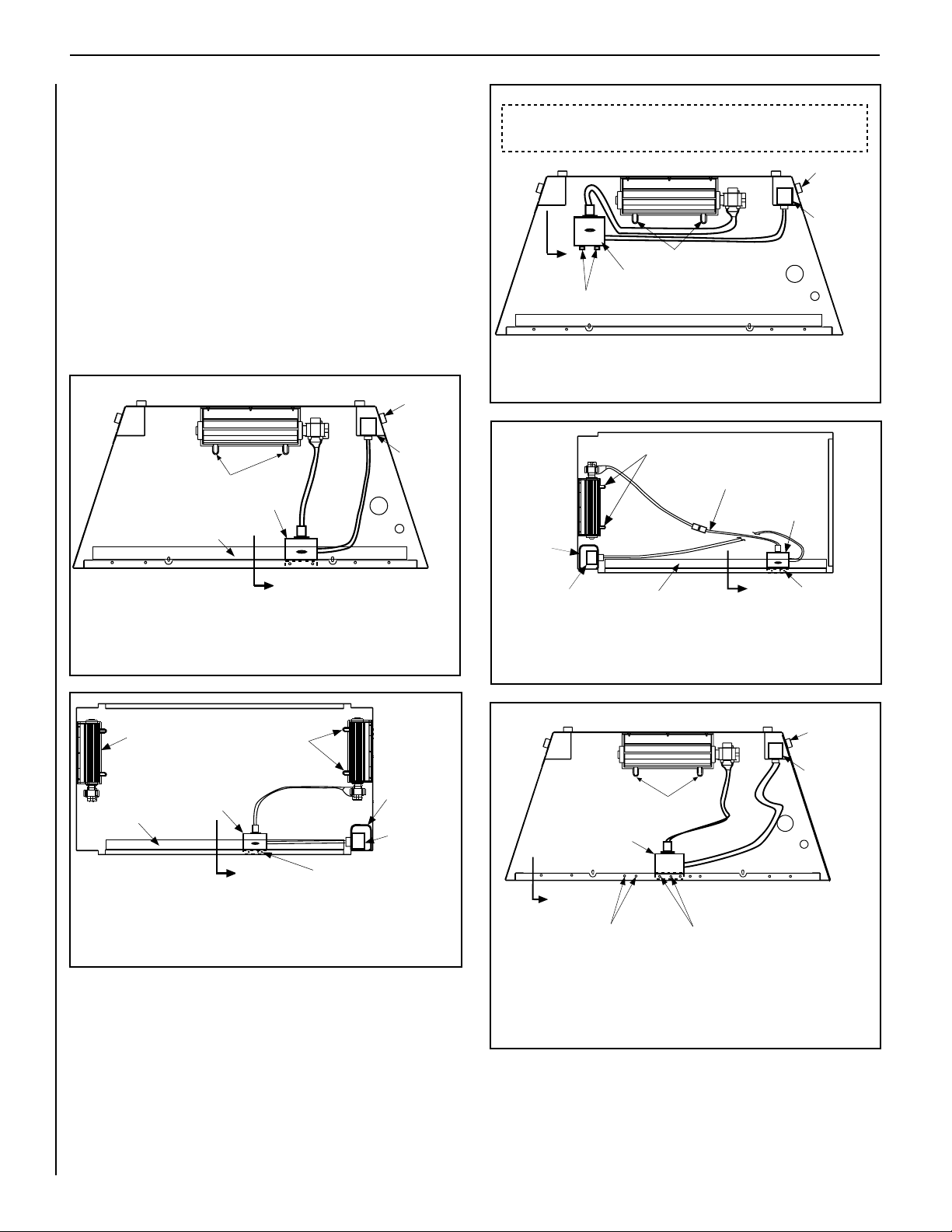
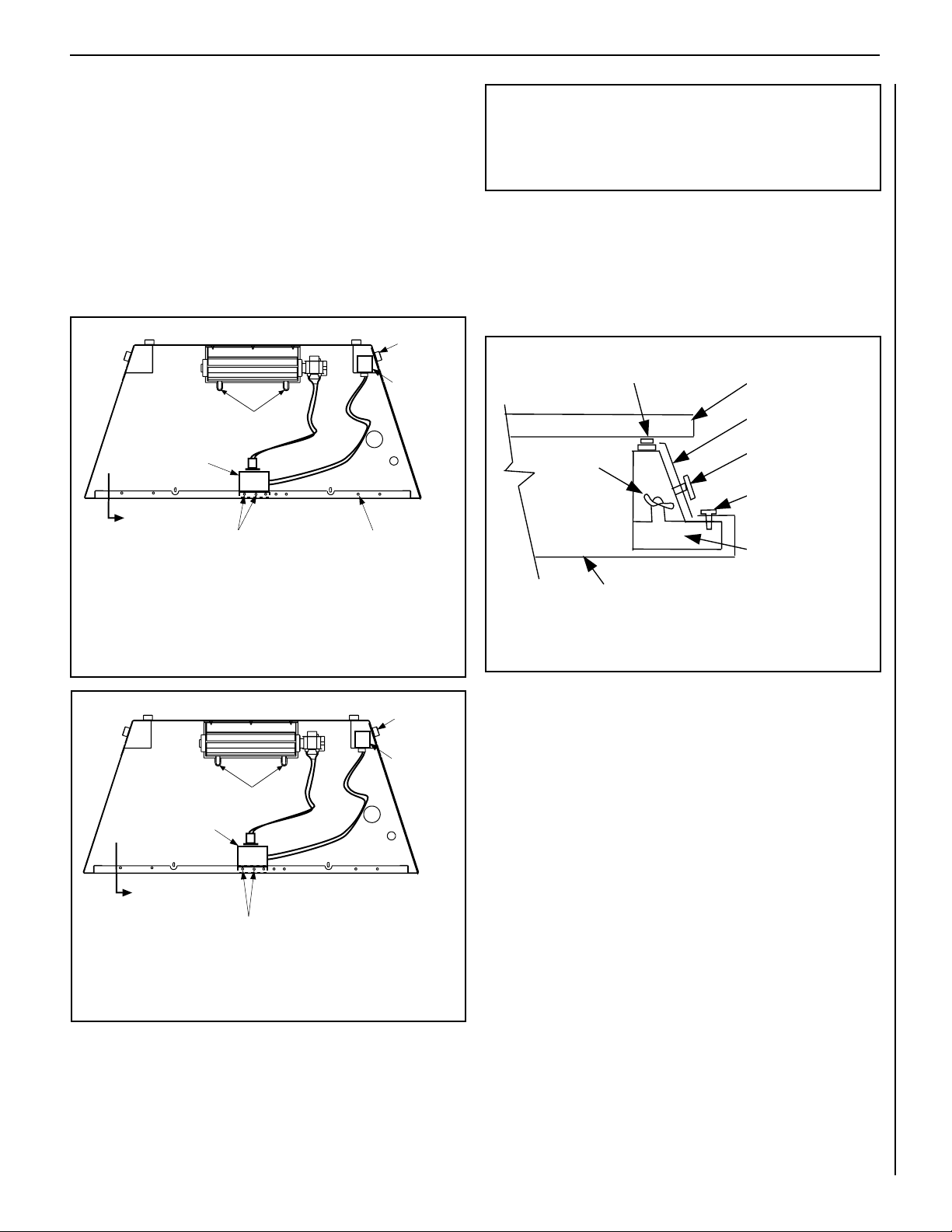
This blower kit may be used with gas fireplaces. The FBK-250 blower kit
is used when unit-mounted variable speed blower control is desired. The
blower is installed beneath the firebox. Room air is drawn in through the
bottom area of the fireplace, heated as it passes across the firebox, and
discharged through the upper panel/louver area at the top of the fireplace.
This kit contains one blower, one speed control module, two speed control
module securing screws and these instructions.
READ ALL THE STEPS BEFORE STARTING THE INSTALLATION THE
FIREPLACE MUST BE OFF AND COLD BEFORE BEGINNING.
ALL WARNINGS, PRECAUTIONS AND INSTRUCTIONS IN THE
INSTALLATION AND OPERATION MANUAL PROVIDED WITH THE
APPLIANCE APPLY TO THESE INSTRUCTIONS.
If you encounter any problems, need clarification of these instructions or
are not qualified to properly install this kit, contact you local distributor
or dealer.
If any of these parts are missing or damaged, contact your dealer or IHP.
us.com for referral information.
WARNING
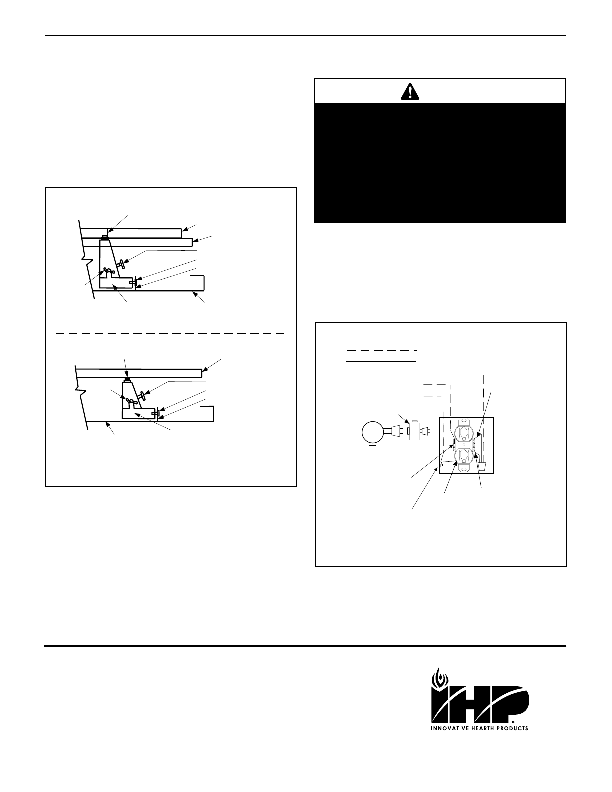
•Blower accessory must be grounded. Blower comes
with a three-prong, grounding plug. The plug is your
protection against electrical shock. Plug it into a stan-
dard, three-hole, grounded, outlet. If cord needs re-
placing, use only a cord with a three-prong, grounding
plug.
•Failure to connect all wires as indicated may cause
electrical shock or personal injury.
CAUTION
Verify proper operation after servicing.
1
unit-mounted variable
speed blower control
module not shown here
WARNING
Reinstall any barrier removed before operating the fire-
place. The barrier is designed to reduce the risk of burns
from hot glass. Do not operate the fireplace without the
barrier installed.
CAUTION
Wear cut resistant gloves and protective clothing during
this process.
INSTALLATION INSTRUCTIONS
1. Turn OFF the fireplace and allow it to cool before proceeding.
2. If the appliance is connected to 120 volt power, disconnect the
power.
3. Shut off the gas supply to the fireplace.
4. Open the lower compartment door (either a radiant panel or louver
assembly) by pushing in simultaneously the left and right side of the
door, or simply lower door down (some doors have hinge pins that
allow the door to be completely removed by pulling pins). Fireplaces
with facades will require the entire facade be removed.
5. D-400, D-500, D-600 and D-800 series; B-500, B-600, and B-800
series; and MDT3328 and MDR3328 Fireplaces - Remove the bot-
tom panel or louver assembly by removing the screw at each end of
the panel or louver assembly, retain the end spacers, and then pull the
panel or the louver assembly from the unit.
Elite-2 Series Fireplaces - Remove the bottom compartment door
(on Multi-Open fireplaces, the modesty-panel-side door) by sliding the
hinge pin, located at the door’s left side, to the right until it disengages
from the left corner post hole. Pull the door diagonally to the left, away
from the fireplace.

INNOVATIVE HEARTH PRODUCTS • KITS AND ACCESSORIES • BLOWER KIT (MODEL FBK-250)
2
NOTE: DIAGRAMS AND ILLUSTRATIONS NOT TO SCALE
BLOWER
JUNCTION
BOX
ELECTRICAL
OUTLET
BLOWER KIT INSTALLATION FOR MULTI-OPEN DIRECT VENT FIREPLACE
(Corner Right)
BLOWER MOUNTING TABS
MODESTY
PANEL
CONTROL
MODULE
VIEW A
FIGURE 8
USE MODULE
HOLES 1 AND 2
(SEE FIGURE 8)
12” MINIMUM FIELD PROVIDED
EXTENSION CORD
BLOWER MOUNTING TABS
BLOWER
JUNCTION
BOX
ELECTRICAL
OUTLET
CONTROL MODULE
BLOWER KIT INSTALLATION
D-400, MDT3328 AND MDR3328 MODELS FRONT-OPEN DIRECT VENT FIREPLACE
TOP VIEW
(Millivolt Connection shown)
Use Module Holes 1 and 2
For Electronic Units (See Figure 8)
(Some units may need
these holes field-provided)
Use Module Holes 1 and 3
For Millivot Units
(See Figure 8)
Holes Shown are Cabinet
Flange Holes
VIEW A
FIGURE 8
Figure 4
Figure 5
BLOWER MOUNTING TABS
BLOWER JUNCTION
BOX
ELECTRICAL
OUTLET
CONTROL MODULE
BLOWER
MOUNTING
TABS
BLOWER
JUNCTION BOX
ELECTRICAL
OUTLET
BLOWER KIT INSTALLATION FOR MULTI-OPEN DIRECT VENT FIREPLACE
(See-through, Peninsula, Corner left)
MODESTY
PANEL
CONTROL
MODULE
VIEW A
FIGURE 8
USE MODULE
HOLES 1 AND 2
(SEE FIGURE 8)
BLOWER MOUNTED
HERE ON MPD35ST
MODEL
BLOWER MOUNTING TABS
BLOWER JUNCTION
BOX
ELECTRICAL
OUTLET
BLOWER KIT INSTALLATION FOR B-VENT FRONT-OPEN FIREPLACE
TOP VIEW
CONTROL MODULE
VIEW A
FIGURE 9
CONTROL MODULE MOUNTING TABS
CAUTION:
ROUTE BLOWER ELECTRICAL CORDS, SO THAT THEY ARE POSITIONED
WELL AWAY FROM THE ROTATING BLOWER PARTS
Figure 1
Figure 2
Figure 3
Control compartment door, access door/
panel, facade & modesty panel location
BLOWER KIT INSTALLATION FOR FRONT-OPEN DIRECT-VENT FIREPLACE, TOP VIEW
VIEW A
FIGURE 8
USE MODULE
HOLES 1 AND 2
(SEE FIGURE 8)
VIEW A
FIGURE 8
6. Elite-2 Series Fireplaces - Remove the modesty panel as follows:
lift the modesty panel by the tab on the panel’s right end, pull the right
end of the panel away from cabinet and then pull the panel diagonally
out of the corner post slots on the left side of the unit. Remove the
modesty panel carefully, so that none of the wires become loose or
disconnected.
7. Front-open direct-vent and B-vent units -
Slide the blower assembly through the front opening to the middle
rear area of the cabinet base. Position the blower assembly so that
the tabs (located on the cabinet base) are seated in the notches of
the blower bracket. Then bend the tabs over to secure the blower
assembly. See Figure 1, direct-vent models; Figure 3, B-vent mod-
els. For Compass and DRL2000 models, if unit is installed into a
wall and front or side access panels are not removable, please see
instructions in installation manual.
BLOWER KIT INSTALLATION FOR MULTI-OPEN DIRECT-VENT FIREPLACE
(See-Through, Peninsula, Corner Left)
BLOWER KIT INSTALLATION FOR B-VENT FRONT-OPEN FIREPLACE
TOP VIEW
BLOWER KIT INSTALLATION FOR MULTI-OPEN DIRECT-VENT FIREPLACE
(Corner Right)

INNOVATIVE HEARTH PRODUCTS • KITS AND ACCESSORIES • BLOWER KIT (MODEL FBK-250)
3
NOTE: DIAGRAMS AND ILLUSTRATIONS NOT TO SCALE
BLOWER MOUNTING TABS
BLOWER JUNCTION
BOX
ELECTRICAL
OUTLET
CONTROL MODULE
BLOWER KIT INSTALLATION
D-500 MODEL FRONT-OPEN DIRECT VENT FIREPLACE
TOP VIEW
(Millivolt Connection shown)
Use Module Holes 1 and 3
For Millivot Units
(See Figure 8)
Use Module Hole 3
For Electronic Units
(See Figure 8)
VIEW A
FIGURE 8
Holes Shown are
Cabinet Flange Holes
BLOWER MOUNTING TABS
BLOWER JUNCTION
BOX
ELECTRICAL
OUTLET
VIEW A
FIGURE 8
CONTROL MODULE
BLOWER KIT INSTALLATION For D-600 and D-800 MODELS
FRONT-OPEN DIRECT VENT FIREPLACE
TOP VIEW
(Millivolt Connection shown)
Use Module Holes 1 and 3 For Millivolt and Electronic Units
(See Figure 8)
Holes Shown are Cabinet Flange Holes
Figure 6
Figure 7
Multi-open direct-vent - Open all remaining bottom hinged-panels. Slide
the blower assembly through the closest opening to the flue side of the
cabinet base. Position the blower assembly so that the tabs (located on
the cabinet base) are seated in the notches of the blower bracket. Bend the
tabs over to secure the blower assembly. See Figure 2 for see-through,
peninsula or corner-left models; Figure 4 for corner right models.
8. If electrical power has not been provided to the unit’s junction box
receptacle - Route a 3-wire, 120 Vac power line to the unit’s junction
box. Remove the receptacle by removing the two securing screws.
Connect the supply wires to the receptacle as shown in Figure 10.
Reinstall the receptacle.
IMPORTANT: Ground lead must beconnectedtothegreenscrewlocated
on the junction box. Failure to do so will prevent the appliance from
operating. The appliance must be electrically grounded in accordance
with local codes or, in the absence of local codes, the National Electrical
Code, ANSI/NFPA 70-latest edition (In Canada, the current CSA C22-1
Canadian Electrical Code).
9. Multi-open direct-vent units - Install a junction box cover (field-
provided) over the junction box.
Figure 8 - DIRECT-VENT MODELS
10. Direct-vent units - Place the front lip of the control module under-
neath the front flange of the cabinet bottom panel as shown in View
A, Figure 8. Secure the module with the two (or one) kit-provided
screw(s).
B-vent units - There are two module mounting tabs located on the cabinet
base just to the left/front of the blower, as shown in Figure 3. Bend these
tabs up, 90 degrees. Place the control module behind the vertical tabs as
shown in Figure 3 and secure the module to the tabs with the two screws
provided in this kit.
11. Adjust the height of the thermal element sensing disk located on
top of the module so that it touches the underside of the firebox
floor in Direct-vent units, B-600/800 units and the firebox sub-floor
in B-500 units. To accomplish this, loosen the wing nut on the mod-
ule’s side, raise the sensing disk housing to the height required above,
then retighten the wingnut. See Figure 8, View A for direct-vent
units, see Figure 9, View A for B-500 units and Figure 9, View B for
B-600/800 units.
12. Plug the blower cord into the module and the module cord into the
top receptacle as shown in Figure 10.
13. Elite-2 Series Gas Fireplaces - Remove the control knob from the
module. See View A, Figure 8. Cut out the circular opening on the
modesty panel sticker that is reserved for the installation of the speed
control module. Reinstall the modesty panel carefully, so that none of
the wires become loose or disconnected. Reinstall the control knob,
then Reinstall the modesty panel. Reinstall the modesty panel care-
fully, so that none of the wires become loose or disconnected. If your
fireplace is not an Elite 2 series, please move to Step 14.
Firebox Bottom Floor
Cabinet Bottom Panel
Wing Nut
Blower Control Module
Control Knob
Modesty Panel
Module Securing
Screws
Adjust Thermal Element Sensing Disk
to Touch Bottom of Firebox floor
View A - Mounting Control Module to Cabinet

INNOVATIVE HEARTH PRODUCTS • KITS AND ACCESSORIES • BLOWER KIT (MODEL FBK-250)
4
NOTE: DIAGRAMS AND ILLUSTRATIONS NOT TO SCALE
120 VAC BLACK
NEUTRAL WHITE
GROUND GREEN
SPEED CONTROL MODULE
Plug Blower into Module and
Module into Top Receptacle.
Tab intact
NEUTRAL SIDE
OF RECEPTACLE
If any of the original wire as supplied must be replaced, it must be
replaced with type AWM 105 degree C - 14 gauge wire.
Green ground screw
RECEPTACLE Red
Black
JUNCTION BOX
HOT SIDE
OF RECEPTACLE
Field Wired
Factory Wired
BLOWER
120V, 60HZ, 1PH BLOWER CONTROL CIRCUIT WIRING
Blower Control Module
Control Knob
Module Securing Screw
VIEW B - MOUNTING CONTROL MODULE TO CABINET
Firebox Bottom Floor
Cabinet Bottom Panel
Wing Nut
Adjust Thermal Element Sensing Disk
to Touch Bottom of FireBox Floor
Module Cabinet Base Tab
Blower Control Module
Control Knob
Module Securing Screw
Firebox Bottom Floor
Cabinet Bottom Panel
Wing Nut
Adjust Thermal Element Sensing Disk To Touch
Bracket On Bottom Of FireBox Sub-Floor
Module Cabinet Base Tab
Firebox Sub-Floor
VIEW A - MOUNTING CONTROL MODULE TO CABINET
Figure 10
Figure 9
14. Reinstall the bottom panel, louver assembly, access door, control
compartment door, facade or Barrier that was removed prior to op-
eration.
15. Restore the electrical power to the unit.
16. Start the fireplace by following the procedure indicated in the lighting
instructions section of the Installation and Operation Instructions
manual, supplied with the fireplace.
17. Check the start up and shutdown, and the running operation of the
blower. Also check the variable speed feature of the speed control.
Direct-vent Units - The approximate blower start time is 15 minutes from
main burner startup. The approximate blower shut off time is 10 minutes
after main burner shut down.
B-Vent Units - The approximate blower start time is 20 minutes from
main burner startup. The approximate blower shut off time is 20
minutes after main burner shut down.
J-BOX WIRING
CAUTION
Ground lead must be connected to the green screw
located on the junction box. Failure to do so will
prevent the appliance from operating. The appli-
ance must be electrically grounded in accordance
with local codes or, in the absence of local codes,
the National Electrical Code, ANSI/NFPA 70—lat-
est edition (In Canada, the current CSA C22.1 Ca-
nadian Electrical Code).
Printed in U.S.A. © 2000 Innovative Hearth Products
P/N 750029M Rev. H 10/2019
Innovative Hearth Products (IHP) reserves the right to make changes at any time, without
notice, in design, materials, specifications, prices and the discontinuance of colors, styles
and products. Consult your local distributor for fireplace code information.
1769 East Lawrence Street • Russellville, AL 35654
This manual suits for next models
1
Other IHP Blower manuals
Popular Blower manuals by other brands

BUFFALO TURBINE
BUFFALO TURBINE BT-MEGA Original instructions and parts manual

Makita
Makita XBU03 instruction manual

Maruyama
Maruyama BL3110 Owner's and operator's manual

Hitachi
Hitachi RB 14DL Technical data and service manual

RADLEY
RADLEY 5073-356 user manual

The Handy
The Handy THEV2600 instruction manual