IISI Cockpit V2 TXG1/2 User manual

IISI Cockpit V2
TXG1/2, TXE30 – 600, TXE-K
Telemetry b ttery m n gement system
for RC model pilots
User m nu l
Softw re Version V2.11
For cert in fe tures, you m y need ddition l p rts, like EXP-T4,
TS60, EXP-LIPO7, etc. For more inform tion,
see www.iisi-rc.com
IISI COCKPIT V2 User M nu l www.iisi-rc.com P ge 1 of 44

1 Wh t’s New?.......................................................................................................................................................................................... 3
2 Applic tions............................................................................................................................................................................................ 5
3 First steps............................................................................................................................................................................................... 6
3.1 The IISI-Link.................................................................................................................................................................................... 6
3.2 P iring............................................................................................................................................................................................. 6
3.3 Setting p r meters on TXE, TXG1/2, TXE-K nd EXP................................................................................................................... 6
3.4 Registering...................................................................................................................................................................................... 6
3.5 Flying with different models............................................................................................................................................................. 7
4 B sic oper tion....................................................................................................................................................................................... 8
4.1 Displ y............................................................................................................................................................................................ 8
4.2 Ch nging v lues............................................................................................................................................................................. 9
4.2.1 Voice output............................................................................................................................................................................. 9
4.3 Al rm levels..................................................................................................................................................................................... 9
4.4 Volume.......................................................................................................................................................................................... 10
5 Screen description................................................................................................................................................................................ 11
6 Cre te configur tion / lo d configur tion........................................................................................................................................... 12
7 Ch nge screens................................................................................................................................................................................... 13
7.1 Ch nge the content of field........................................................................................................................................................ 13
7.2 Ch nging the size of field........................................................................................................................................................... 14
7.3 Add nother screen....................................................................................................................................................................... 14
7.4 Remove screens........................................................................................................................................................................... 14
8 Voice output settings............................................................................................................................................................................ 15
8.1 Rem ining c p city....................................................................................................................................................................... 15
8.2 Altitude nnouncement.................................................................................................................................................................. 16
8.3 V rio sounds................................................................................................................................................................................. 16
8.4 Speed nnouncements................................................................................................................................................................. 16
9 Al rms................................................................................................................................................................................................... 18
10 Cockpit Settings.................................................................................................................................................................................. 19
10.1 Glob l Settings............................................................................................................................................................................ 19
10.2 Voice settings (glob l)................................................................................................................................................................. 19
10.3 Model specific settings 1/2 for Cockpit re ction.......................................................................................................................... 20
10.4 Model specific settings 2/2, controlling with RC switch............................................................................................................... 21
10.5 D t Logger................................................................................................................................................................................ 21
10.6 M inten nce................................................................................................................................................................................ 23
10.6.1 EXP/TXE FW Upd te.......................................................................................................................................................... 23
10.6.2 Softw re Version.................................................................................................................................................................. 23
10.6.3 Adv nced Settings............................................................................................................................................................... 24
11 Beh vior when switching on model................................................................................................................................................. 28
11.1 Full b ttery................................................................................................................................................................................... 28
11.2 B ttery not full, first flight fter switching on the Cockpit............................................................................................................. 28
11.3 B ttery not full, doing multiple flights with s me b ttery (Fly-Ag in)........................................................................................... 29
11.4 Flying with different b ttery configur tions.................................................................................................................................. 29
11.4.1 Different cell numbers.......................................................................................................................................................... 29
11.4.2 Different c p cities............................................................................................................................................................... 30
12 Configur tion of the TXE.................................................................................................................................................................... 31
12.1 TXE50 to TXE600-E.................................................................................................................................................................... 31
12.2 TXG1 / TXG2............................................................................................................................................................................... 33
12.2.1 Choosing TXG1 or TXG2?................................................................................................................................................... 33
12.3 Using nd c libr ting the TS300................................................................................................................................................. 33
12.4 Estim ted flight time.................................................................................................................................................................... 34
12.4.1 Multicopter........................................................................................................................................................................... 34
12.4.2 Helicopter............................................................................................................................................................................. 35
12.4.3 Electric glider....................................................................................................................................................................... 35
12.4.4 Others.................................................................................................................................................................................. 35
12.5 Multi motor models...................................................................................................................................................................... 35
13 Ch rging the Cockpit, oper tion time................................................................................................................................................. 36
14 Softw re Upd tes............................................................................................................................................................................... 36
15 The microSD c rd............................................................................................................................................................................... 38
16 Av il ble fields.................................................................................................................................................................................... 40
17 W rr nty............................................................................................................................................................................................. 44
18 Conformity.......................................................................................................................................................................................... 44
19 Dispos l.............................................................................................................................................................................................. 44
20 Support............................................................................................................................................................................................... 44
IISI COCKPIT V2 User M nu l www.iisi-rc.com P ge 2 of 44

1 Wh t’s New?
Version V2.11
-Voice output nd screen c n be controlled with switch on your r dio (using V2RC nd EXP-RC-LINK p rts)
-Support for new p rts : TXG1/2 V2RC, TXE-K, EXP-RC-LINK
-Estim ted flight time c n be referenced to l rm level (see Adv nced Settings)
-C p city estim tor c n be shown lw ys t st rt-up, including when using LIPO7 (Adv nced Settings)
-Volt ge displ y c n be selected s cell volt ge or tot l b ttery volt ge (Adv nced Settings)
-N mes for % v lues nd temper tures c n be entered on Cockpit
-The b ttery n me stored in LIPO7 is displ yed nd logged to identify which b ttery h s been used
-Cockpit switches off when ch rging is interrupted
-French di lects c n be selected directly on Cockpit
-When model is switched off, you c n select between "l nded", nother sound, or nothing (Adv nced Settings)
-More st ble, simplified USB communic tion
-Better ch rging beh vior nd b ttery level indic tion
-Multiple sensors re (T4, RPM2) re now enumer ted from 1-4
-EXP-T4 c n be used twice in system, llowing 8 temper ture sensors
-Low ltitude l rm c n be progr mmed with positive v lues
-GPS position displ y bug fix
-EXP-RPM / BLS1 configur tion bug fix
Version V2.10
-IMPORTANT: Al rm levels re now lw ys stored on Cockpit! See Al rms
-Precise displ y for rem ining flight time / motor run time (e.g. for Multicopters, electric gliders, etc.) See
Estim ted flight time
-Support of multi motor models / b tteries (TXE V2, RPM2), see Multi motor models
-Single cell monitoring of p r llel (up to 14S2P) b tteries with EXP-LIPO7
-Al rms c n be suppressed during flight without looking t screen
-Cockpit c n listen to other TXEs, e.g. for observer, c mer oper tor, etc. See Adv nced Settings
-TXE oper tion time c n be set to specific v lue. See Configur tion of the TXE
-Support for new EXP-GAS nd extended r nge temper ture sensor (TS300) See Using nd c libr ting the
TS300
-Bug fixes nd optimiz tions
-New firmw re for TXE nd EXP
-New speech d t , l rm sounds
Version V2.05
-Unp cker bug fix
-Log d t c n now displ yed directly on Cockpit
-Autom ted ch nge of d ylight s ving time
-Configur ble v rio frequencies
-Support of new EXPs: GPS2, AVM2, RPM2, US1, FTX2
-Moved r rely used settings to “Adv nced settings”
-Don’t show l rms in configur tion displ y when set to “Al rms on Cockpit”
-TXE flight counter c n be set to individu l v lue
-Configur tions c n be s ved utom tic lly
-RUV files re copied / deleted together with CFG files
-TXG1 registr tion bug fix
-Optimized touch screen
-Some new / modified fiels
Version V2.03
-Fly Ag in d ptive c p city s well with EXP-LIPOx
-Correct gr phic l ltitude displ y
-Bug fixes with TXE / TXG1 configur tion
-New field for ltitude bove se level (with EXP-GPS)
-Support of EXP-AVM2 nd GPS2
IISI COCKPIT V2 User M nu l www.iisi-rc.com P ge 3 of 44

Version V2.01
-Announcement for c p city in cert in settings
-List of l rms directly ccessible (D t Logger)
Version V2.00
The numbering of the softw re for Cockpit V2 h s been d pted to V2.xx, in order to void versioning with Cockpit V1
(V1.xx).
New functions:
-Al rms re nnounced with ctu l v lues
-Voice nnouncement settings c n be s ved directly, lso for ll v il ble models
-System l rms c n be configured now in the EXP/TXE list field
-The c p city of full b ttery c n be ch nged immedi tely t st rt with one click (Full b ttery)
-3 new flight counters: 1 flights per d y counter, 2 independent nd set/resett ble through the new field “flight
counters”
-List with ll new flight counters of ll models, nd tot l flights of the d y (D t Logger)
-List with l rms of the flight
-From V2.00 on, there’s only one file needed for softw re upd te. It c n cont in im ge.bin, EXP nd TXE
upd tes, new voice d t etc.
-Screen shots c n be c ncelled
-Log d t c n be org nized lso by models: MODEL-DATE-TIME
-BM2 c libr tion
-Announcement for link lost nd link b ck c n be suppressed (voice settings in the field “RSSI”)
-Al rm when multiple TXEs re on
-Log d t c n be visu lized with LogView Studio. A test rele se c n be requested t dominik@logview.info. Soon
you c n find the fin l rele se t www.logview.info
Bug fixes:
-EXP-T4 temper ture l rms
-Security l rms
-Voice output for c p city
-TXG1 registering
-Not found udiod t when configuring l rms
IISI COCKPIT V2 User M nu l www.iisi-rc.com P ge 4 of 44

2 Applic tions
IISI is telemetry b sed b ttery m n gement concept for electric lly powered RC models. It ssists the pilot in n
efficient w y during the flight or run bout the b ttery st te (fuel g uge). When the b ttery becomes ne rly empty, the
pilot is informed bout it n c n l nd s fely, without stress. This ensures lso longer life of the b tteries.
The IISI System is speci lly designed for models with LiPo b tteries, independent of the model type (pl ne, helicopter,
ship or c r).
The inst ll tion nd configur tion of the IISI System is extremely simple, while experienced users c n configure it
individu lly for their needs (voice output, l rms, screen definitions, …)
Multiple IISI systems c n be used t the s me time – there’s no ch nnel selection necess ry.
The IISI system gives you multiple dv nt ges:
Before the flight:
Autom tic check of b ttery st te – no st rts without fully ch rged b tteries
Recognizes multiple flights with the s me model nd b ttery: Full control when you fly g in with p rti lly
disch rged b ttery – even if you h ve used other models during th t time.
Full control over current consumption, power, volt ge, temper ture, cell volt ge levels ( ddition l p rts needed)
During the flight:
Displ y rem ining flight time (e.g. for multicopters), d t v il ble fter bout 15s!
Fully progr mm ble voice output:
oB ttery is low (c lcul ted rem ining c p city, not only volt ge level b sed)
oToo low b ttery volt ge
oM ximum current or m ximum temper ture1 exceeded
oCritic l volt ge or volt ge drift of cells detected2 (b l ncing)
Shows / nnounces current, volt ge, power, rem ining c p city, etc. (gr phic l nd numeric), now lso
controll ble with switch on your r dio (using TXG1/2 V2RC or EXP-RC-LINK)
Autom ted voice ouput for volt ge s g, current pe k, speed records, m x. ltitude
Shows tot l flight time nd tot l motor run time
Current nd m ximum temper ture*
Al rms, when pre-defined v lues re exceeded
E.g. speed tr ining with ddition l EXP modules, indic te position nd flight direction
After the flight (inform tion rem ins visible) / in gener l:
Shows lowest b ttery volt ge nd highest current during the flight
Used / rem ining c p city
Tot l flight time (of current flight, or of tot l flights)
Number of flights (progr mm ble flight counters, flights per d y)
D t logger, stores directly re d ble .csv files on the microSD c rd
IISI helps you to choose the best b ttery fit reg rding current (C-r ting) nd flight time. Don’t c rry too he vy
b tteries within your model
No off-field l ndings nymore due to empty b tteries
Longer b ttery life s deep disch rge is efficiently voided
Use LogView Studio, D t Explorer or Excel to visu lize log d t ; visu lize GPS d t on Google E rth ®
IISI COCKPIT V2 User M nu l www.iisi-rc.com P ge 5 of 44

3 First steps
The IISI Telemetry System works with so-c lled TXEs, which combine current sensor, volt ge sensor, c p city
me surement nd telemetry tr nsmitter in one p rt. The TXEs re built fix into model (pl ne, helicopter, bo t, c r, …)
nd deliver re l time d t for current, volt ge, c p city, flight time, etc.
The Cockpit V2 is the telemetry receiver which serves s displ y, voice output, stor ge of flight d t nd much more.
Further, the n me “Cockpit” is used.
3.1 The IISI-Link
E ch IISI Product communic te with the IISI link. This interf ce uses the st nd rd 3pole connectors, s used for servos,
etc. The IISI link h s the following functions:
P iring, configur tion of ll TXEs nd EXPs
Connection of single temper ture sensor (TS60), if no other EXPs re connected
Connection of one or more (up to 4) EXPs (use Y c bles to connect more th n one EXP)
Please note that in spite of the similar connectors and cables, no servos, receivers, etc. are allowed to be connected to
the IISI-Link! Connect only IISI products to the IISI link!
The IISI Cockpit recognizes utom tic lly if TXE or n EXP is connected to it’s IISI link for configur tion.
Important
If you connect a TXE, TXG1 or an EXP to the Cockpit, it is powered through the Cockpit (with some exceptions)
Connect only one EXP or TXE at a time to the Cockpit. More than one EXP / TXE connected through a Y-cable
won’t work.
EXP-LIPO6/BM2 These are OPTO products and need to be powered (connected to a battery on the balancer /
bat1 connector), otherwise, the Cockpit cannot communicate with them.
3.2 Pairing
In order to logic lly connect your TXE with your Cockpit, you need to p ir them first. Without this procedure, the IISI
Cockpit c nnot recognize your TXE. This llows using multiple IISI systems t the s me time.
The TXE nd TXG1c nnot be connected directly to the Cockpit’s IISI-Link. Use the progr mming c ble included with
your Cockpit.
If p iring is needed, it is shown on the screen. This is n utom tic process. Be sure th t none of your other TXEs is
powered on during th t time. After p iring, you will get directly into the configur tion menu.
Note: EXPs do not need to be p ired with the Cockpit. Only if you need to set p r meters on the EXP, you h ve to
connect them to the Cockpit. EXP-LIPOx nd BM2 need to be powered by b ttery for this.
3.3 Setting arameters on TXE, TXG1/2, TXE-K and EXP
Cert in settings need to be done on the TXE or EXP directly. To do this, simply connect the TXE/TXG1, TXE-K to the
Cockpit with the included progr mming c ble. The EXPs c n be directly connected to the Cockpit.
The menu for the connected device is utom tic lly st rted. Ple se note th t the Cockpit must be w ke to recognize
connected device.
In the TXE, you need to set model n me, the def ult c p city, b ttery type nd l rm levels. See more det ils bout
this in the ch pter Configur tion of the TXE.
After this, the system is re dy nd you c n st rt flying.
3.4 Registering
When model is powered on, the TXE n lyses the connected b ttery nd tr nsmits inform tion to the Cockpit.
Depending on your b ttery (full or not full), the Cockpit will register the TXE directly nd st rt its norm l oper tion (full
IISI COCKPIT V2 User M nu l www.iisi-rc.com P ge 6 of 44

b ttery), or it will sk you wh t to do (not full b ttery). To help you bit with this, the Cockpit cont ins b ttery st te
estim tor, which llows you to guess how much is still in there.
This process is c lled registering.
IMPORTANT: Only correct TXE settings llow the correct oper tion nd norm l registering.
3.5 Flying with different models
The Cockpit cre tes one memory pl ce per model (per TXE or TXG1) on the microSD c rd in the folder /CFG. The
memory pl ce c rries the s me n me you’ve given to your model, stored in the TXE. Th t’s why it’s import nt you give
every model different n me. The TXEs V2 (second gener tion) c n be upd ted to V3.x with the Cockpit. This gives
you 8 ch r cters for model n me, inste d of 4 with older TXEs.
Every memory pl ce, n med “configur tion”, cont ins model specific settings for screen definition (YES, the screen c n
be person lized!), voice output (how often, nd when), l rms, vibr l rm, etc. This me ns you c n p r meterize nd
d pt the screen(s) the w y you w nt them look for every different model. Decide how much it t lks, nd t which levels
l rms re triggered.
All v lues you ch nged re referencing to the selected configur tion. On the lower border of the screen you c n lw ys
see the model n me (which is lso the configur tion n me). After switching on the Cockpit, the st nd rd configur tion
“DEFAULT_” will be lo ded. When you switch on e.g. your model c lled “HELI_5”, the configur tion “HELI_5___” is
lo ded.
When you ch nge something in the current configur tion, the n me will be printed inversed, letting you know th t you
should s ve it. By clicking on the configur tion n me, you c n s ve it on the microSD c rd.
Here you c n lso lo d n existing configur tion nd modify it without switching on the model.
The model is automatically loaded in the Cockpit as soon as a model is switched on. There’s no manual load or model
change needed!
IISI COCKPIT V2 User M nu l www.iisi-rc.com P ge 7 of 44

4 B sic oper tion
Switch on and off: Switch your Cockpit on by pressing shortly on the button, loc ted t the top side of the Cockpit. By
pressing it for bout 1 second, you c n switch it off. Holding it for longer time ( bout 10s) will reset the Cockpit nd
rest rt it.
The touch screen is of „resistive type“, which me ns, it needs slight mech nic l pressure to oper te correctly. The
following ctions re possible:
-„Click“: T p on specific point on the screen to trigger n ction, rel ted with the displ yed d t below.
-„Push“: push longer time on specific point on the screen to show the options v il ble for the displ yed d t
below.
-„Horizont l wipe“: from right to left or vice vers , to ch nge screens. St rt the wipe with slight pressure nd
continue to press slightly until the end, moving your finger with moder te speed.
-„Vertic l wipe“: S me s bove, but in vertic l direction. This is for incre se / decre se volume nd to scroll in
settings menues.
-„Di gon l wipe“: Wipe from one corner to the opposite one (it doesn’t m tter where you st rt). This brings the
Cockpit into the settings menu. You le ve the settings menu the s me w y you entered it.
On the left side, you c n connect n e rphone (3.5mm j ck) or other udio devices. The spe ker will be switched off
then.
On the right side, you c n find the mini USB connector, which llows ch rging the Cockpit’s b ttery. You c n use ny
USB ch rger with t le st 500mA of current c p bility. The Cockpit h s ch rging controller which regul tes current etc.
The USB interf ce llows lso to communic te with the Cockpit (microSD c rd). It cont ins udio, configur tion nd log
d t . The Cockpit beh ves like m ss stor ge device (memory stick). We recommend you to do regul r b ckups of the
CFG nd LOG d t on your computer.
With your PC (or M c, Linux, …), you c n delete, copy, form t etc. s usu l. You shouldn’t ch nge the d t yourself, it
m y result in str nge beh vior of the Cockpit. Alw ys eject the drive before removing the USB connection. Should the
microSD c rd become unre d ble, you m y h ve to reform t it nd copy the udio d t to it g in.
The 3pin connector is the IISI-Link. It serves to configure TXEs nd EXPs nd s n interf ce for softw re upd te to
these devices.
NEVER connect volt ge supply to the IISI-Link, it will destroy p rts in the Cockpit, the TXE or the EXPs!
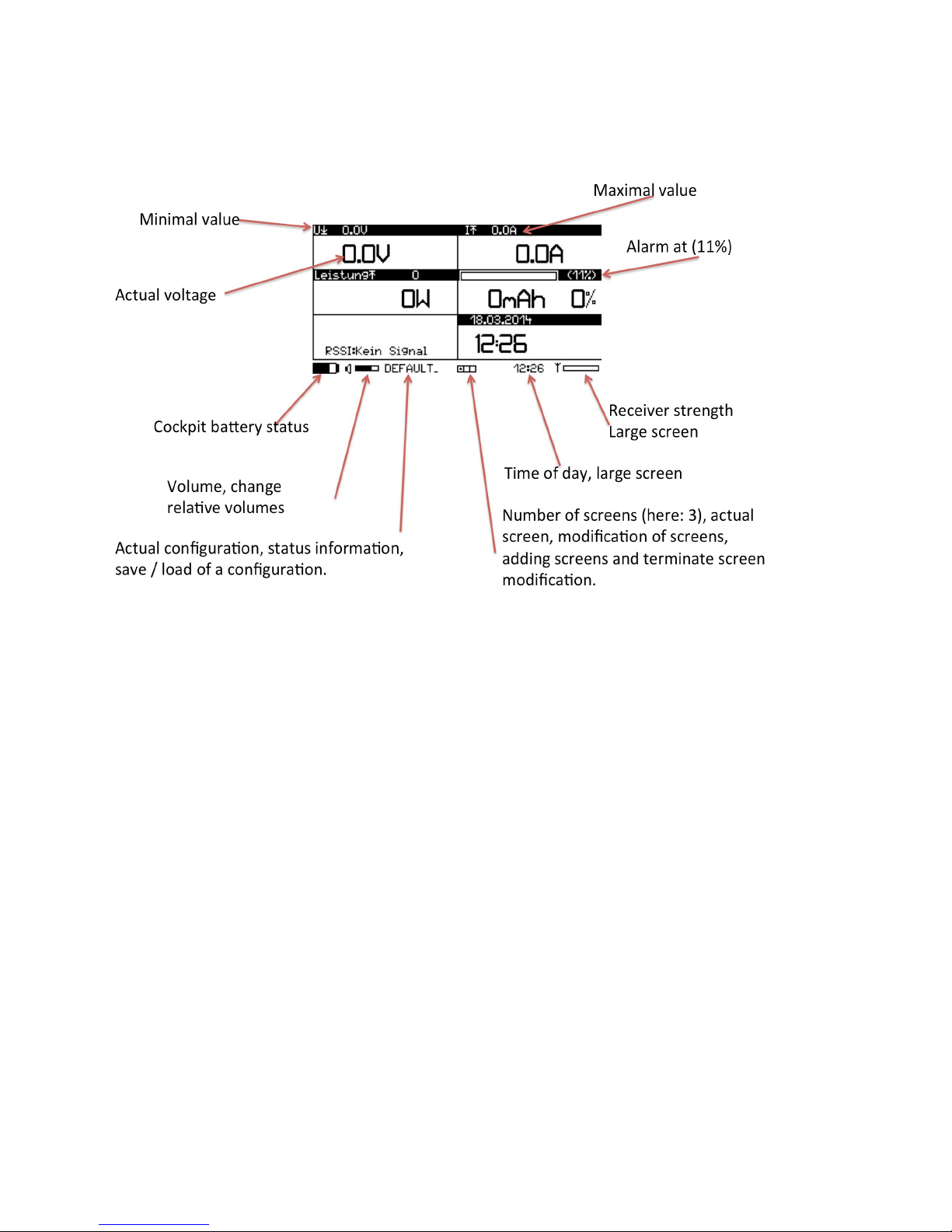
4.1 Dis lay
The displ y is sep r ted in 2 re s: Below, you c n find the st tus inform tion of the Cockpit. The content is expl ined
s follow (from left to right):
-St te of the Cockpit b ttery
-Volume (click on it to open the volume settings screen)
-Configur tion n me – m y ltern te with st tus inform tion. Click on it to lo d or s ve configur tion.
-Number nd position of screens. E ch little squ re represents one screen. The selected screen is filled with
dot. Click on these squ res to enter the “screen modific tion menu”.
-Time of d y; click on it to m ke it full screen
-Receiver strength; click on it to m ke if full screen
The upper p rt is split into 6 fields which ll c n show one telemetry v lue. The size of the left fields c n be ch nged
(click on --- or +++ on the lower side). To ch nge the screens, you must enter the screen modific tion mode first (by
clicking on the squ res s described bove). Select the field you w nt to ch nge (it is inverted then). By clicking on the
left or right side of the selected field, you c n ch nge its function.
The fields on the left c n lso be ch nged in size (click on --- or +++ t the lower border).
Not ll fields re v il ble in l rger sizes.
Should you w nt to dd new screen, just click on the squ res nd select “Add”. Up to 8 screens c n be displ yed.
Should you w nt to delete screen, just empty ll fields. When le ving the screen modific tion mode, empty screens
will be deleted.
Don’t forget to s ve your configur tion if you w nt to keep your new screens.
IISI COCKPIT V2 User M nu l www.iisi-rc.com P ge 8 of 44

IMPORTANT: Should you use EXPs nd you h ve no rel ting field displ yed nywhere on your screens, some fields
th t re rel ted to this EXP re dded. For ex mple: If you use EXP-LIPO7, nd no cell volt ge field is displ yed
nywhere, these fields re utom tic lly dded when the TXE + EXP is registered. If you like, to c n modify these
settings then nd s ve the configur tion. Next time, you will see your screens ex ctly the s me w y s you s ved them.
4.2 Changing values
The h ndling of the Cockpit is gener lly “context sensitive”: Should you ch nge something rel ted to current, go to the
screen th t displ ys the current nd push on this field. You will see the options to select from, like l rm levels, voice
output, zoom, etc. Speci l settings like n mes for temper ture sensors, zeroing ltitude etc. re selected by using the
wrench symbol.
One exception is the Cockpit’s settings menu. It is entered nd exited by wiping di gon lly over the screen.
4.2.1 Voice out ut
Princip lly, you c n only he r v lues which re lso displ yed on one of the m x. 8 screens. It doesn’t m tter if the
screen is ctu lly displ yed or not. Ex mple: Should your screen show full screen fuel g uge, the v lues for current,
volt ge, power, etc. which re loc ted on nother screen, will nyw y be nnounced.
The voice output h s no fixed scheme. You c n person lize it in wide r nge. Depending on their v lue (current,
volt ge, ltitude, speed) you m y select specific options to ctiv te the voice output controlled on time b se, or rel ted
to the v lues.
V lues, which re outside the l rm level, re nnounced norm lly, while v lues which re “under l rm” will be
nnounced s “critic l”.
The time interv ls for norm l or critic l nnouncements c n be individu lly progr mmed, s well s trigger levels for
v lue-controlled nnouncements. You lso c n choose to set them to silent.
Voice output settings re modified by pushing on the v lue field nd then selecting the “mouth” icon.
Time interv l controlled nnouncements:
“Speech every 60s”: The nnouncement will be repe ted every 60 seconds, if the v lue is outside the l rm level. The
time c n be progr mmed individu lly or switched off.
“Announce when critic l 10s”: The nnouncement will be repe ted ll 10 seconds, if the v lue is inside the l rm level.
The time c n be progr mmed individu lly or switched off.
V lue-controlled nnouncements:
“At ch nge of 50A”: You will he r the nnouncement of the current, when the v lue h s ch nged t le st by 50Amps
since the l st nnouncement (or meters, degrees, volts, etc. depending on the v lues). The level c n be progr mmed
individu lly or switched off.
Specific v lue-controlled nnouncements re described below.
4.3 Alarm levels
Alarm levels are exclusively stored in the model configuration, located on the SD card of the Cock it. Alarm
values of TXE and EXPs are ignored! The V2.10 software su orts you during this change, should you still use
“Alarms on TXE” settings.
Exce tion: The default ca acity is still located on TXE or EXP-LIPOx.
Ch nge l rm levels by pushing on the desired v lue then select the l rm bell. The rrow shows if it is n l rm level
for exceeding (up) or f lling below v lue (down). Sometimes, both re possible. In the l rm settings m sk you c n
then modify the l rms, sounds, vibr , repe ts, etc.
Al rm settings re stored in the .CFG file of e ch model.
IISI COCKPIT V2 User M nu l www.iisi-rc.com P ge 9 of 44

4.4 Volume
The volume c n be ch nged by vertic l wipe, or by selecting the volume menu (click on the loudspe ker symbol on
the lower left p rt of the screen). There you c n select the m ster volume (for ll udio) nd the rel tive volumes for:
-Speech: Rel tive volume for norm l nnouncements (norm lly t bout 85%)
-V rio: Rel tive volume for v rio beeps (norm lly t bout 50%)
-Al rms: Rel tive volume for l rms (norm lly t 100%)
You c n click on these fields for test listening.
Do not overlo d the spe ker, the sound should rem in cle n. Otherwise, the spe ker m y be d m ged.
IISI COCKPIT V2 User M nu l www.iisi-rc.com P ge 10 of 44
5 Screen description
The screen shown below is just n ex mple, it c n be modified completely to your needs.
IISI COCKPIT V2 User M nu l www.iisi-rc.com P ge 11 of 44

6 Cre te configur tion / lo d configur tion
Every model h s its own configur tion. The n me stored in the TXE is used for identific tion. When you power up
p ired TXE the first time, the Cockpit will sk you to select either the st nd rd configur tion (DEFAULT_) or copy one of
the existing ones (th t you m y h ve cre ted e rlier). After this, the Cockpit stores the configur tion under its new n me
(of the TXE). The lo ded configur tion is shown t the lower p rt of the screen (red zone). If a model is switched on,
the corresponding configuration is automatically loaded, if it is already present.
When the n me of the configur tion is displ yed reversed, the configur tion d t h s been ch nged nd needs to be
s ved, if you w nt to keep the ch nges.
When you click on the configur tion n me, you c n choose between s ving (SAVE) or lo ding n existing configur tion
(LOAD). When you lo d configur tion, you c n edit it nd s ve it fterw rds, e.g. for offline modific tions t home,
without powering up the model.
You c n choose if modified configur tions re utom tic lly stored or if you w nt to do this yourself. (see Adv nced
Settings)
You lso c n delete nd cre te new configur tions. This is described in the p rt M inten nce.
IISI COCKPIT V2 User M nu l www.iisi-rc.com P ge 12 of 44
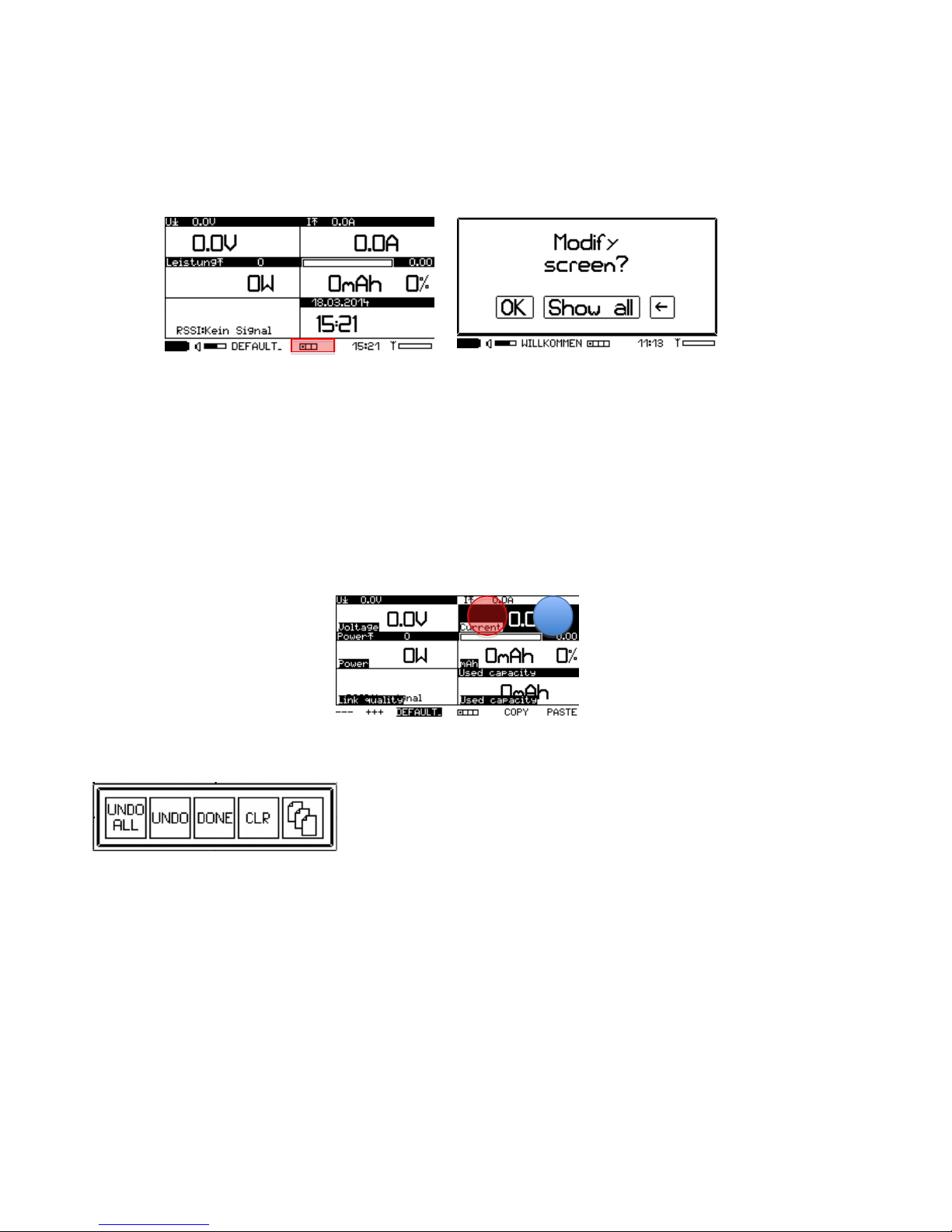
7 Ch nge screens
When you w nt to modify screen, insure first th t the correct configur tion is lo ded (e.g. model is powered up or the
configur tion h s been lo ded m nu lly.
By clicking the squ res on the lower p rt of the screen (red zone) you c n enter the “screen modific tion” mode.
7.1 Change the content of a field
The norm l screen is now shown with one inverted (selected) field (e.g. the current) nd c n be ch nged.
Wiping left nd right llows you to ch nge screens s usu l.
If you click on the right p rt of the field (blue zone), the next field type is chosen. A click on the red zone chooses the
former field type. Fields which re not defined re utom tic lly byp ssed.
A list of v il ble fields you c n find under Av il ble fields.
A simple click on nother field selects it. You c n copy fields by selecting COPY nd PASTE it t nother pl ce.
When you push on field in the “screen modific tion” mode, 4 or 5 icons ppe r. You c n choose between these
options:
-UNDO ALL: undo ll ch nges since the l st entry in this mode
-UNDO: undo the ch nges on the ctu lly selected field only
-DONE: le ve the “screen modific tion” mode
-CLR: Cre tes n empty field
-When fields support multiple inst nces (like RPM, temper ture, %-v lues etc.) you see n ddition l icon with
multiple documents. If you choose this, you c n select which inst nce will be shown on this field (0 for the
norm l or m ster inst nce, 1-3 for further (sl ve) inst nces. TXE or EXP must be configured ccordingly in order
to m ke this work. If multiple inst nces re present, they will be m rked on the top right corner with #M for
norm l or m ster inst nce, #1 for inst nce 1, etc.
Other fields which use multiple sensors / v lues of the s me type, use lso this option, in order to select one of
the 4 possible v lues.
Please note that this o tion is ONLY available in the "modify screen" mode!
IISI COCKPIT V2 User M nu l www.iisi-rc.com P ge 13 of 44

7.2 Changing the size of a field
The fields on the left c n be incre sed in size (twice s l rge, 2x higher, 3x higher). Use the --- nd +++ to ch nge size.
When you decre se field, empty fields re inserted t the no more utilized re s.
7.3 Add another screen
To dd n ddition l screen or termin te the “screen modific tion” mode, click on the squ res t the lower p rt of the
screen.
With “Add”, you c n dd nother screen (up to 8). When you’re done, select “Done” to go b ck to the norm l mode.
7.4 Remove screens
When you le ve the “screen modific tion” mode, empty screens will be deleted.
If you w nt to remove screen, you need to set ll fields to “empty”. The e siest w y: select the filed on the upper right
corner, set it to “empty” (e.g. use CLR, see bove), then incre se the field using +++ to the m ximum size nd b ck to
the sm llest size using ---. This will cre te n empty screen. Then quite the modify screens mode by clicking on the
squ res g in nd select “Done”.
IISI COCKPIT V2 User M nu l www.iisi-rc.com P ge 14 of 44

8 Voice output settings
The voice output c n be customized to fit ex ctly your need of inform tion during the flight.
Only v lues which re shown on one of the screens will be nnounced. Otherwise, even if the module tr nsmits these
v lues, but they re not displ yed nywhere, will not be nnounced.
Any ch nge on the voice outputs reg rding v lue (e.g. current) is done by pushing on the corresponding field. Then
select the mouth symbol to get to the nnouncement m sk:
The inversed fields h ve the following functions:
-AKTIVE (or SILENT): The nnouncement is ctiv ted or muted.
-“Announce norm l every 60S”: The nnouncement for current is done every 60 seconds, if not bove the l rm
level. (OFF me ns no timely controlled nnouncement).
-“Announce when critic l 10s”: The nnouncement for current is done every 10 seconds, if current is bove the
l rm level. (OFF me ns no timely controlled nnouncement).
-“At ch nge of 12.0A”: If the current ch nges by 12Amps (since the l st nnouncement), new nnouncement is
triggered.
-Announce pe k current: If the current goes bove this v lue, the current is nnounced, when the current f lls
below this v lue, or when the time window expires, wh tever h ppens first. It is lw ys the m ximum current
nnounced which is me sured during the ctive period. Ple se note you c n do the s me on volt ge drops in
the “volt ge” field.
-CANC quits nd c ncels your ch nges
-OK quits nd confirms your settings. You m y w nt to s ve then the configur tion to m ke these ch nges
perm nent.
-SAVE stores the nnouncement settings in the model configur tion. You c n choose if the settings should be
stored only in the now lo ded configur tion or for ll existing models. This is useful for e.g. dis bling n
unw nted nnouncement for ll models.
Different v lues h ve lso different speech control settings:
8.1 Remaining ca acity
The rem ining c p city voice output c n ne controlled on time interv l b sis nd/or b sed on % ge steps.
When both options re ctiv ted, you m y here repe ted nnouncement.
Addition lly to the time interv l controlled nnouncement, you c n choose:
-„Norm l ll 10%“: While the rem ining c p city is bove the l rm threshold level (e.g. 20%) the rem ining
c p city is nnounced ll 10% steps (so 90, 80, 70, …)
-„Critic l ll 5%“: As soon s the reserve c p city level h s been re ched (set in the l rm settings), the
nnouncements re m de ll 5% steps, st rting from the l rm level . Ex mple: 20%, 15%, 10%, 5%, 0%.
IISI COCKPIT V2 User M nu l www.iisi-rc.com P ge 15 of 44

Ple se note: If l rm nd nnouncement should be triggered t the s me v lue (e.g. 20%), it c n be th t the
nnouncement is not triggered lthough it shows lre dy 20%. This is due to rounding (when the c p city is e.g. 20.4%)
8.2 Altitude announcement
The nnouncement for ltitude h s speci l settings:
The first 3 lines beh ve s usu l (timely controlled, or t ch nge of ltitude since the l st nnouncement).
-“Ann. fter strong ch nge On”: After strong rise or f ll, the ltitude is nnounced (e.g. fter cutting off your
motor of the glider). C n be switched off.
-„Ann. when re ched Off“: You c n progr m n ltitude here. When this ltitude is re ched, the nnouncement is
triggered (e.g. 300m)
8.3 Vario sounds
The v rio sounds h ve no voice output. Inste d of them, you c n set the p r meters for the v rio sounds here. The
v rio sounds frequency c n be modified in Adv nced Settings.
These p r meters re ct s follow:
-„Rising limit: Off “ V rio sounds re pl yed s soon s rising is detected. Set limit v lue here (e.g. 50cm/s) in
order to suppress v rio sounds from 0 – 49cm/s.
-„Sinken b:“ S me, but for sinking r tes.
-„Don’t’ beep bove Off“: When off, v rio sounds re produced for ny rise/sink r tes. Should you w nt to
suppress them t high v lues (e.g. when doing crob tics or if you use your motor to climb), you c n set limit
here (e.g. 500cm/s), so th t bove 5m/s rise/sink r te, v rio sounds re suppressed.
PLEASE NOTE: Ple se upd te your EXP-AVM to the l test softw re version for correct oper tion! (V3.x)
8.4 S eed announcements
The nnouncements for speed c n be controlled timely s usu l.
Further, IISI provides you very innov tive tool for speed tr ining:
-„Store top speed > 150km/h“: Above the chosen v lue, top speed me surement is ctiv ted. The f stest speed
is stored tempor rily.
IISI COCKPIT V2 User M nu l www.iisi-rc.com P ge 16 of 44

-„Announce top speed 50km/h“: Below the chosen v lue, the top speed me surement is termin ted nd the
f sted speed of the ctu l tri l (see bove) is nnounced (the 3 most recent top speed results re visible in the
speed v lue field). This will lso reset the top speed me surement fe ture.
Hint: If you w nt speed nnouncement bove cert in speed, you c n do the following:
Set the “ nnounce when critic l” to short time, e.g. 3s. Then go to the speed l rm settings nd set the l rm to the
desired limit (e.g. 150km/h) nd switch the l rm to OFF. Now, you’ll he r speed nnouncements every 3 seconds when
your model m kes over 150km/h.
IISI COCKPIT V2 User M nu l www.iisi-rc.com P ge 17 of 44
9 Al rms
Tr dition lly, l rms in the IISI System were stored in the sensors nd re tr nsmitted to the Cockpit. This is no more
the c se with Version V2.10: All l rms re stored on the cockpit in the model configur tion file (.CFG). Al rm levels c n
be modified during the flight s well.
If you lre dy h d configured the l rm levels “on Cockpit”, you don’t need to do nything. Otherwise, you’ll be sked to
verify ll l rms of ll your models in the cockpit (c n be c ncelled).
Very import nt: E rlier, before V2.10, both c p city l rm level (e.g. 20%) nd volt ge l rm (e.g. 3.3V) h d been stored
on the TXE.
The w y how l rms re set re identic l for ll v lues. Every v lue h s its own l rm level, some v lues h ve 2 l rm
levels (e.g. over- nd under temper ture).
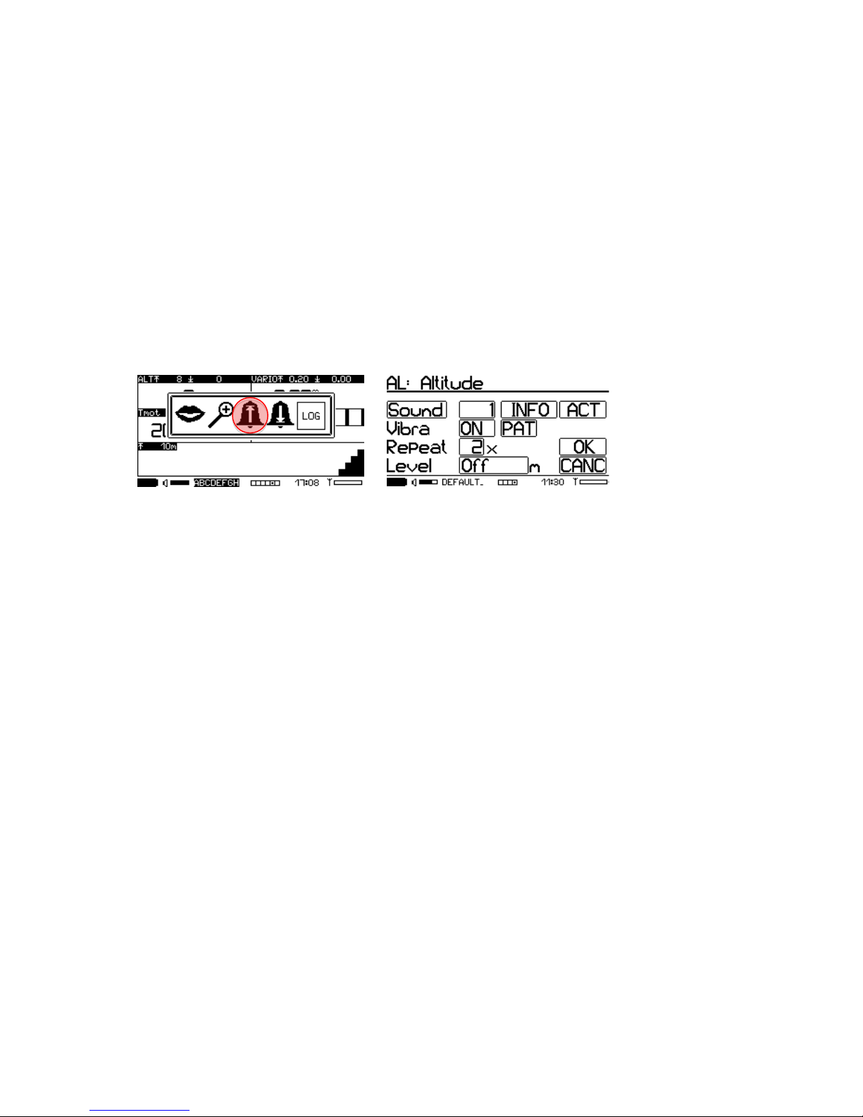
Push on the v lue field to show the icons with the v il ble options nd select the l rm bell. The rrow shows if the
l rm level is for going over (up) or going below (down). All l rm v lues re set in the l rm menu:
As n ex mple we show the ltitude l rm settings:
By clicking on the l rm bell, you get to the m sk “Al rm settings”:
-“Sound”: Click on it to he r the l rm, including vibr , repe ts, etc. how it will be pl yed if the l rm occurs. The
number right to “Sound” is the sound number: e.g. 3 will pl y the file _ l rm03. if udio file in the folder
AUDIO/SND. You c n lso cre te your own udio files (google “Aud city” for free udio editor). You c n lso
switch this v lue to “off”, so no sound is pl yed.
-INFO: If this field is ctiv ted, you’ll he r the v lue which c used the lert, it’s type (e.g. over current) nd the
units (e.g. mps). Is it de ctiv ted (----) only the l rm sound nd “ l rm” is he red.
-“Al rm ON” or “OFF” will ctiv te or de- ctive the l rm. The l rm level will lw ys be used for the
nnouncements (critic l…), independently if the l rm is switched on or off.
-“Vivr ”: “ON” ctiv tes vibr tion l rm, “OFF” dis bles it.
-“PAT”: For every l rm, you c n define your own vibr tion p ttern (32 steps)
-“Repe t”: How m ny times the sound selected bove will be pl yed. The nnouncement “e.g. b ttery empty” will
only be spoken once.
-“Level”: This is the l rm level. When the rel ted v lue goes below or bove this level (depending of the l rm
type selected before), the l rm will be ctiv ted. C n be switched to off, which m kes the l rm in ctive. If
utom tic s ve of the configur tion is ctiv ted or if you s ve the configur tion m nu lly, the level is
perm nently modified for this model. If it is not s ved, it is only v lid during this flight.
“OK” quits the menu nd confirms your ch nges, “CANC” quits nd c ncels your ch nges. You m y w nt to s ve the
configur tion to keep your ch nges perm nently (or it is utom tic lly s ved when this is ctiv ted. See Adv nced
Settings.
Hint: If you he r n l rm during the flight, which is not w nted (e.g. ltitude) you c n de ctiv te this for the actual
flight by t pping 3 times f st on the screen during the lert.
If you t p only once on the screen during the lert, the nnouncement is stopped, but the l rm rem ins ctiv.
IISI COCKPIT V2 User M nu l www.iisi-rc.com P ge 18 of 44

10 Cockpit Settings
The Cockpit Settings menu cont ins glob l settings for the Cockpit, v lild for ll models, but lso some model specific
settings.
You c n enter nd exit this menu by wiping di gon lly over the screen (in ny direction). The Cockpit remembers the
l st used screen nd shows it when entering.
10.1 Global Settings
These settings re for the Cockpit nd therefore v lid for ll models!
Re-arm alarms:
-„YES“ me ns th t l rms re re- ctiv ted, once the l rm condition is resolved. Al rms c n h ppen multiple
times per flight.
-„NO“ me ns th t l rms re not re- ctiv ted, they only c n h ppen once per flight.
Ex mple volt ge l rm with re- rm set to “ON”: When the volt ge drops below the l rm level due to high current, the
l rm m y trigger. When the current is reduced, the volt ge goes up g in nd the l rm condition is resolved. Next
time, when volt ge drops below the l rm limit, the l rm will trigger g in.
When set to “OFF”, the second l rm will not trigger, so you must be c reful once you’ve he red n l rm.
Contrast:
The contr st c n be djusted to get cle n im ge. Should bl ck re s be too gr y, you c n incre se contr st. Should
you see dirty white re s, sh dows etc. you should decre se the contr st. On very cold d ys you m y incre se the
contr st to get f ster re ction of the screen.
Backlight:
Select the strength of the b cklight:
-0: Off
-1: Night light
-2: h lf power
-3: M ximum light
The b cklight switches off when the Cockpit goes to sleep mode. The time for sleep mode c n be djusted (see below).
10.2 Voice settings (global)
Glob l p r meters for the voice output:
IISI COCKPIT V2 User M nu l www.iisi-rc.com P ge 19 of 44

Language: (Voice output nd menu l ngu ge)
-„DE“ for Germ n
-„EN“ for Englisch
-„FR“ for French
Alarm announcements
-Al rm: A l rm is nnoucned with the word “ l rm” nd with the selected l rm sound.
-Infos: Inform tion reg rding the v lue which c used the l rm is nnounced.
If de ctiv ted, these settings pply glob lly for ll l rms (individu l settings possible in the l rm menu).
Registriering talk (when selected, the tone will be pl yed, otherwise not)
-„TXE On“: This is the sound you he r when new TXE is detected by the Cockpit. The sound file is loc ted in
/AUDIO/SND nd is in st nd rd .AIF form t. You c n repl ce it with your own sound file, if you w nt (file
_new_txe. if).
-„Avbl C p.“: When the model is registered, you he r the phr se “Av il ble c p city …” You c n suppress this if
you w nt.
-„Nice fl.“: When the model is registered, the Cockpit wishes you nice flight. You c n suppress this if you w nt.
Config announ.
Typic lly, the voice output follows this scheme: “Type of v lue” – “V lue” – “Unit”, e.g. “Current” - “76.6” - “Amps”.
-„Typ“: When selected, the v lue is preceded by its type (e.g. “current”)
-„Unit“: When selected, the v lue is followed by its unit (e.g. “Amps”)
-„I-A“: Intelligent Announcement: When the s me type of v lue is repe ted within short time (15s), the I-A mode
will suppress the type nd unit, to void useless t lking. As soon s nother type of v lue is nnounced, you’ll
he r the complete nnouncement (depending on wh t you’ve selected for type nd unit bove. An ex mple:
“Current 65 mps, 63, 51, 21, volt ge 46.7 volts, current 35 mps, 44, 42, 39, …”. Ple se note th t the I-A mode
only m kes sense when type nd/or unit re selected.
10.3 Model s ecific settings 1/2 for Cock it reaction
In most c ses you don’t w nt the Cockpit to t lk continuously nd you m y w nt to reduce the nnouncements to
minimum. In some c ses, you’d like to know specific inform tion immedi tely. Or you m y h ve ccess to other
functions in very simple w y. Th t’s wh t this screen is for:
For every model, you c n define wh t should h ppen in one of the 2 c ses: 1) click nywhere on the screen nd 2)
sh ke the Cockpit. (ple se don’t forget to s ve the model configur tion once you’re s tisfied with the settings you
m de).
Action ta :
The st nd rd setting is “ nnounce shown v lue”, which me ns th t the v lue you click on is nnounced.
-„Ann. Fix“: This option will let you choose ny v lue (e.g. c p city). This v lue will be nnounced every time you
click on the screen ( nywhere). So you c n blindly click on the screen to ctiv te the nnouncement of the
desired v lue.
-„<<>>“: When you click on the screen, the next screen is selected (inste d wipe over the screen)
-„Zoom“: You c n choose ny v lue (which h s v lid full screen definition) to be shown s full screen. When
you click g in, the screen goes b ck to norm l mode.
-„Vol“: A click on the right side of the screen incre ses volume, click on the left side decre ses it
-„AVM“: Clicking nywhere on the screen will toggle the v rio sound ctiv tion / muting.
Action shake:
The st nd rd setting is “None”, th t me ns no ction. Any ction c n be defined (simil r to the ones described bove),
when the Cockpit is sh ked (left / right).
“Stop” will stop ny nnouncement if you sh ke the Cockpit.
IISI COCKPIT V2 User M nu l www.iisi-rc.com P ge 20 of 44
This manual suits for next models
2
Table of contents
Popular Remote Control manuals by other brands

Graco
Graco 3A1907C Instructions - parts

Feit Electric
Feit Electric OneSync UCL/REMOTE1 Important Safety Instructions and Installation Guide

Cardin
Cardin S449 QZ2 Programming manual

Mitsubishi Electric
Mitsubishi Electric PAC-SE51CRA Operation manual

Philips
Philips SRU 3040/10 Instructions for use

RadioLink
RadioLink T7F-2.4Ghz instruction manual


