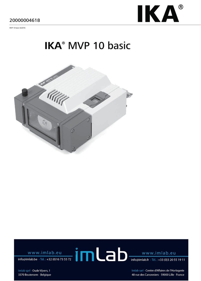
IKA MVP 10 basic User manual

IKA MVP 10 basic
Betriebsanleitung DE 4
Ursprungssprache
Operating instructions EN 12
Mode d’emploi FR 20
Руководство пользователя RU 28
使用说明 ZH 36
Biztonsági utasitások HU 55
Varnostna navodila SL 56
Bezpečnostné pokyny SK 57
Ohutusjuhised ET 58
Drošības norādījumi LV 59
Saugos nurodymai LT 60
Инструкции за безопасност BG 61
Indicaţii de siguranţă RO 63
Υποδείξεις ασφαλείας EL 64
Indicaciones de seguridad ES 44
Veiligheidsaanwijzingen NL 45
Avvertenze per la sicurezza IT 46
Säkerhetsanvisningar SV 47
Sikkerhedshenvisninger DA 48
Sikkerhetsinformasjon NO 49
Turvallisuusohjeet FI 50
Instruções de segurança PT 51
Wskaz
ó
wki bezpieczeństwa PL 53
BezpeČnostní upozornĕnÍ CS 54

3
Item Designation
AMains Switch
BGas Ballast
CGas Inlet
DHandle
ESupply cable
FGas Outlet
Fig. 1
A
B
C
D
E
F
Pos. Bezeichnung
A Hauptschalter
B Gasballast
C Gaseinlass
D Griff
E Netzkabel
F Gasauslass
Поз. Обозначение
AГлавный выключатель
BГазобалластный вентиль
CПатрубок для впуска газа
DРучка
EКабель сетевого питания
FПатрубок для выпуска газа
Rep. Désignation
A Interrupteur principal
B Ballast gaz
C Entrée gaz
D Poignée
E Câble secteur
F Sortie gaz
编号 名称
A电源开关
B气镇阀
C进气口
D把手
E电源线
F出气口

54
• Lesen Sie die Betriebsanleitung vor Inbetriebnah-
me vollständig und beachten Sie die Sicherheits-
hinweise.
• Bewahren Sie die Betriebsanleitung für alle zugänglich
auf.
• Beachten Sie, dass nur geschultes Personal mit dem Gerät
arbeitet.
•
Beachten Sie die Sicherheitshinweise, Richtlinien, Arbeits-
schutz- und Unfallverhütungsvorschriften.
•
Tragen Sie Ihre persönliche Schutzausrüstung entspre-
chend der Gefahrenklasse des zu bearbeitenden Mediums.
Ansonsten besteht Verletzungsgefahr durch Glasbruch.
Die Pumpe nicht bei offener Front-
abdeckung betreiben. Ansonsten
besteht die Gefahr schwerer Ver-
letzungen durch Einziehen der Hand in sich bewegende
Teile, da innenliegende Pumpenteile mit sehr hoher Ge-
schwindigkeit drehen.
• Vor dem Einschalten des Geräts stets sicherstellen, dass
die Frontabdeckung angebracht ist.
• Die Pumpe nicht anheben, wenn die obere Motorabde-
ckung nicht sicher befestigt ist.
•
Die Pumpe nicht einschalten, wenn sie senkrecht steht, da
sie in dieser Stellung nicht lagestabil ist.
Sicherheitshinweise
Inhaltsverzeichnis
DE
EU-Konformitätserklärung
Ursprungssprache
• Die Pumpe darf nur betrieben werden, wenn sie horizon-
tal steht.
• Die Pumpe vor dem Einschalten auf einer stabilen und ebe-
nen Oberfläche aufstellen.
Das Einatmen von bzw. der Kontakt
mit Medien wie giftigen Flüssigkei-
ten, Gasen, Sprühnebel, Dämpfen,
Stäuben oder biologischen Stoffen kann gesundheitsge-
fährdend für den Anwender sein. Sicherstellen, dass alle
Anschlüsse dicht und leckfrei sind, wenn mit solchen Me-
dien gearbeitet wird.
• Das Pumpensystem ist nicht ex-geschützt ausgelegt. Si-
cherstellen, dass die Temperatur des mit dem Vakuum
evakuierten Mediums unterhalb der Zündtemperatur
liegt. Auf Temperaturstieg des Mediums während dem
Evakuieren achten.
Zeichenerklärung
Allgemeiner Gefahrenhinweis
Mit diesem Symbol sind Informationen gekennzeichnet, die für die Sicherheit Ihrer Gesund-
heit von absoluter Bedeutung sind. Missachtung kann zur Gesundheitsbeeinträchtigung
und Verletzung führen.
Mit diesem Symbol sind Informationen gekennzeichnet, die für die technische Funktion des
Gerätes von Bedeutung sind. Missachtung kann Beschädigungen am Gerät zur Folge haben.
Mit diesem Symbol sind Informationen gekennzeichnet, die für den einwandfreien Ablauf
der Gerätefunktion sowie für den Umgang mit dem Gerät von Bedeutung sind. Miss-
achtung kann ungenaue Ergebnisse zur Folge haben.
GEFAHR
WARNUNG
VORSICHT
GEFAHR
GEFAHR
Seite
EU-Konformitätserklärung 4
Zeichenerklärung 4
Sicherheitshinweise 5
Bestimmungsgemäße Verwendung 6
Auspacken 6
Wissenswertes 6
Aufstellung 7
Inbetriebnahme 8
Instandhaltung und Reinigung 8
Zubehör 9
Störungsbehebung 10
Technische Daten 11
Gewährleistung 11
• Betreiben Sie das Gerät nicht in explosionsgefährdeten
Atmosphären, mit Gefahrstoffen und unter Wasser.
• Arbeiten mit dem Gerät dürfen nur im überwachten Be-
trieb durchgeführt werden.
• Zwischen Medium und Antriebseinheit können elektrosta-
tische Vorgänge ablaufen und zu einer direkten Gefähr-
dung führen.
• Sicheres Arbeiten ist nur mit Zubehör, das im Kapitel „Zu-
behör“ beschrieben wird, gewährleistet.
• Nur autorisiertes Personal darf die Demontage des Gerä-
tes vornehmen.
• Die Trennung des Gerätes vom Stromversorgungsnetz er-
folgt nur durch Ziehen des Netz- bzw. Gerätesteckers.
• Die Steckdose für die Netzanschlussleitung muss leicht er-
reichbar und zugänglich sein.
• Den druckseitigen Ausgang der Vakuumpumpe in den La-
borabzug verlegen.
• Die Betriebsanleitung der Ausrüstung (z.B. Rotationsver-
dampfer) beachten, mit der die Vakuumpumpe verbun-
den ist.
• Der Motor wird bei Überhitzung durch einen thermischen
Schutzschalter in der Wicklung abgeschaltet:
- In diesem Fall ist eine manuelle Rücksetzung erforder-
lich. Das Gerät ausschalten oder die Ausrüstung vom
Netz trennen. Etwa fünf Minuten vor dem erneuten Ein-
schalten des Gerätes abwarten.
- Das Gerät unter den im Abschnitt „Technische Daten”
angegebenen Bedingungen betreiben.
• Die Pumpe nicht zur Druckerzeugung verwenden.
•
Der Druck am Gaseinlass oder -auslass darf max. 1 bar
betragen.
•
Falls mehrere Lasteinrichtungen vorhanden sind, Mag-
net-/Rückschlagventile verwenden.
• Nur flexible Schlauchleitungen verwenden.
Zum Schutz des Gerätes
• Spannungsangabe des Typenschildes muss mit Netzspan-
nung übereinstimmen.
• Die verwendete Steckdose muss geerdet sein (Schutzlei-
terkontakt).
• Abdeckungen bzw. Teile die ohne Hilfsmittel vom Gerät
entfernt werden können, müssen zum sicheren Betrieb
wieder am Gerät angebracht sein, damit zum Beispiel das
Eindringen von Fremdkörpern, Flüssigkeiten etc. verhin-
dert wird.
• Vermeiden Sie Stöße und Schläge auf Gerät oder Zubehör.
• Das Gerät darf nur von einer Fachkraft geöffnet werden.
• Um eine ausreichende Kühlung des Antriebes zu gewähr-
leisten, dürfen die Lüftungsschlitze am Antrieb nicht ab-
gedeckt werden.
• Nur Original-Ersatzteile zur Instandhaltung verwenden,
um den zuverlässigen Betriebszustand des Gerätes zu ge-
währleisten.
Wir erklären in alleiniger Verantwortung, dass dieses Produkt den Bestimmungen der Richtlinien 2014/35/EU, 2006/42/EG,
2014/30/EU und 2011/65/EU entspricht und mit den folgenden Normen und normativen Dokumenten übereinstimmt: EN
61010-1, EN 61326-1, EN 60529 und EN ISO 12100.
Eine Kopie der vollständigen EU-Konformitätserklärung kann bei [email protected] angefordert werden.

76
• Auf Wasserkondensation innen und außen am Gerät ach-
ten. Das Gerät zuerst erwärmen lassen, falls es aus einer
kalten Umgebung hereingebracht wurde.
• Die Pumpe nicht zum Austragen von Feststoffen verwen-
den
, da dies die Membran und Innenteile der Pumpe be-
schädigen würde.
Bestimmungsgemäße Verwendung
•Verwendung
Zusammen mit dem von IKA empfohlenen Zubehör ist
das Gerät geeignet für:
- Evakuieren von Gas aus Laborgeräten (z.B. Rotations-
verdampfer).
Betriebsart: Tischgerät.
• Verwendungsgebiet
Laborähnliche Umgebung im Innenbereich in Forschung,
Lehre, Gewerbe oder Industrie.
Der Schutz für den Benutzer ist nicht mehr gewährleistet:
- Wenn das Gerät mit Zubehör betrieben wird, welches
nicht vom Hersteller geliefert oder empfohlen wird
-
Wenn das Gerät in nicht bestimmungsgemäßem Ge-
brauch entgegen der Herstellervorgabe betrieben wird
- Wenn Veränderungen an Gerät oder Leiterplatte durch
Dritte vorgenommen werden.
• Auspacken
- Packen Sie das Gerät vorsichtig aus
- Nehmen Sie bei Beschädigungen sofort den Tatbestand
auf (Post, Bahn oder Spedition).
Auspacken
• Lieferumfang
- Vakuumpumpe IKA MVP 10 basic
- Betriebsanleitung
.
Membranvakuumpumpen (auch Membranpumpen ge-
nannt) sind oszillierende Verdrängerpumpen. Die Membra-
nen erzeugen durch Expandieren des Volumens in der Va-
kuumkammer ein Vakuum, das wiederum den Druck in der
Vakuumkammer herabsetzt und somit bewirkt, dass atmo-
sphärische Luft in die Kammer einströmt. Die Luft in dieser
Kammer wird dann mit Hilfe von Ventilen über einen an-
deren Weg (Gasauslass) aus der Vakuumkammer gedrückt.
Diese periodischen Bewegungen der Membran erzeugen
ein Vakuum (Unterdruck) am Pumpeneingang.
Besondere Vorsicht ist beim Arbeiten mit Gasmischungen
geboten, die kondensierbare Gase enthalten (z.B. Wasser-
dampf oder Lösemittel).
Der Einsatz der Membranpumpe IKA MVP 10 basic mit
solchen Gasen führt zu deren Kondensation irgendwo im
Luftstrom der Pumpe. Dadurch wird in der Vakuumkammer
ein Druck aufgebaut, der wiederum die Nutzlebensdauer der
Membranen und Ventile verkürzt.
Wissenswertes
Um Kondensation zu vermeiden bzw. von der Pumpe ge-
bildete Kondensate abzulassen,sollte das Gasballastventil
geöffnet werden. Durch Öffnen des Gasballastventils wird
eine geringe Menge Luft in die Vakuumkammer eingelas-
sen, so dass die Konzentration des kondensierbaren Gases
herabgesetzt wird. Das Ablassen der Kondensation kann
auch erfolgen, indem für mehrere Minuten das Durchströ-
men der vollen Gasmenge unter Atmosphärendruck durch
die Pumpe zugelassen wird.
Verwenden Sie zum Schutz der inneren Ventile und Mem-
branen einen vorgeschalteten Kondensatabscheider (zum
Beispiel: Woulff’sche Flasche an den IKA Rotationsver-
dampfer RV 8 und RV10).
Das Austreten von Lösemitteldämpfen in die Athmosphäre
kann mit einem nachgeschalteten Ablasskondensator ver-
mieden werden.
Der Abluftschlauch sollte prinzipiell in eineen Laborabzug
münden.
Ein montierter Abluftschlauch dient ebenfalls zur Geräusch-
reduzierung.
• Die Pumpe nicht zum Austragen von Flüssigkeiten verwen-
den, da dies die Lebensdauer der Membran verkürzen und
zu Leckage führen würde.
• Die Verträglichkeit der mit dem Gerät verwendeten Sub-
stanzen mit den Werkstoffen der „Medienberührten
Teile” des Gerätes sicherstellen; siehe Abschnitt „Tech-
nische Daten”.
Aufstellung
Konfigurationen:
IKA MVP 10 basic Vakuumpumpe und Vakuumregler an eine Vakuum-Lasteinrichtung angeschlossen.
IKA®MVP 10 basic
Elektrische Verbindungsleitungen
Vakuumschlauch
Spannungsversorgung
Rezipient
Auslass Einlass
Pumpensteuerung
Vakuum Controller
Magnetventil

98
Inbetriebnahme
Instandhaltung und Reinigung
D
as Gerät arbeitet wartungsfrei. Es unterliegt le
diglich der
natürlichen Alterung der Bauteile und deren statistischer
Ausfallrate.
Reinigung
Zum Reinigen den Netzstecker ziehen.
Reinigen Sie IKA-Geräte nur mit von IKA freigegebenen Rei-
nigungsmittel.
Diese sind: (tensidhaltiges) Wasser und Isopropanol
Tragen Sie zum Reinigen des Gerätes Schutzhandschuhe.
Elektrische Geräte dürfen zu Reinigungszwecken nicht in
das Reinigungsmittel gelegt werden.
Beim Reinigen darf keine Feuchtigkeit in das Gerät dringen.
Falls andere als die empfohlenen Reinigungs- oder Dekon-
taminationsmethoden angewendet werden, fragen Sie bit-
te bei IKA nach.
Instandhaltung
•
Demontage der oberen Abdeckung: Entfernen Sie die
obere Gehäuseabdeckung durch Lösen der 4 Boden-
schrauben.
• Die Schläuche durch Sichtprüfung auf Risse untersuchen.
Falls sich Risse gebildet haben oder der Schlauch brüchig
wird, ist dieser durch einen geeigneten neuen zu ersetzen.
• Verwenden Sie zum Reinigen des Gerätegehäuses nur
Wasser mit einem tensidhaltigen Reinigungsmittel bzw.
Isopropanol bei hartnäckigen Verschmutzungen.
Den Vakuumschlauch zwischen Gaseinlass und Rezipient
anschließen. Netzstecker an das Stromnetz anschließen und
den Hauptschalter (A, siehe Fig. 1) in Stellung ‘I’ legen, um
das Gerät einzuschalten.
Lösen der 4 Schrauben
Ansicht ohne die obere Gehäuseabdeckung
Verwenden des Gasballastventils
•
Sicherstellen, dass der Luft-/Gaseinlass
durch das Gasballastventil niemals zu reak-
tiven, explosiven oder anderweitig gefähr-
lichen Mischungen führt, die von der Va-
kuumpumpe am Einlass gefördert werden.
• Beim Entspannen (Belüften)des Rezipienten
oder der Vakuumpumpe mit Umgebungs-
luft besteht unter Umständen die Gefahr
von erheblichen Schäden an Ausrüstung
und/oder Umgebung, von ernsthaften
Verletzungen oder auch Lebensgefahr be-
dingt durch die Bildung von gefährlichen
und/oder explosiven Mischungen, falls Luft
und gepumpte Medien in der Pumpe oder
am Pumpenauslass miteinander reagieren.
Zum Pumpen von kondensierbaren Dämpfen (Wasser-
dampf, Lösemittel usw.):
• Die Pumpe mit geschlossenem Gasballastventil laufen las-
sen, bis sie ihre Betriebstemperatur erreicht hat.
• Das Gasballastventil öffnen (siehe Abb. unten).
• Das Gasballastventil ist geöffnet, wenn die Kerbe auf dem
Deckel mit der Kerbe auf dem Stutzen ausgerichtet ist
(Schließen des Gasballastventils durch Drehen des Deckels
um mindestens 90°).
•
Durch Öffnen des Gasballastventils wird der Endvakuum-
druck reduziert und die Pumpgeschwindigkeit herabge-
setzt.
• Inertgas am Lufteinlass verwenden, um das Entstehen ex-
plosiver Gasgemische zu vermeiden.
Ersatzteilbestellung
Bei Ersatzteilbestellungen geben Sie bitte Folgendes an:
- Gerätetyp,
- Seriennummer, siehe Typenschild des Produkts,
-
Positionsnummer und Bezeichnung des Ersatzteils, siehe
www.ika.com.
Reparaturfall
Bitte senden Sie nur Geräte zur Reparatur ein, die
gereinigt und frei von gesundheitsgefährdenden
Stoffen sind.
Fordern Sie hierzu das Formular „Unbedenklichkeitser-
klärung“ bei IKA an oder verwenden Sie den download
Ausdruck des Formulares auf der IKA Website www.ika.
com.
Senden Sie im Reparaturfall das Gerät in der Originalverpa-
ckung zurück. Lagerverpackungen sind für den Rückversand
nicht ausreichend. Verwenden Sie zusätzlich eine geeignete
Transportverpackung.
Zubehör
Refer to IKA website (www.ika.com)
Offen
Beachten Sie die in den technischen Daten angegebenen
Umgebungsbedingungen (Temperatur, Feuchte).

1110
Technische Daten
Nenn-Betriebsspannung VAC 230 ± 10% (EURO)
115 ± 10% (USA)
Betriebsspannungsbereich VAC 200 – 240 (EURO)
100 – 120 (USA)
Frequenz Hz 50 / 60
Anschlussleistung bei Nennspannung W180
Nennstrom A0,8
Endvakuum (absolut) mbar <10
Endvakuum (absolut) mit Gasballast mbar 15
Drehzahl ohne Last rpm 1380 / 50Hz
1680 / 60Hz
Einlass Schlauchtülle NW 10
Auslass Schlauchtülle NW 10
Max. zulässiger Auslassdruck (absolut)
bar 1
Max. Druckdifferenz zwischen Einlass und Auslass bar 1,1
Abmessungen (B x T x H) mm 245 x 320 x 155
Gewicht Kg 11,5
Schutzart IP 54
Zulässige Umgebungstemperatur für Lagerung/Betrieb °C - 10 ... + 60 / + 5 ... + 40
Zulässige Feuchte %80 (Temperaturen bis 30 °C)
Motorschutz Thermischer Schutzschalter
Geräteeinsatz über NN mmax. 2000
Medienberührende Werkstoffe
Komponenten Medienberührende Teile
Vakuumtrichtereinsatz PTFE, carbonfaserverstärkt
Vakuumtrichter ETFE, carbonfaserverstärkt
Membranklemmscheibe ETFE, carbonfaserverstärkt
Ventil
EFPM
Membran PTFE
Einlass / Auslass / Fittings ETFE
Auslass ETFE
Technische Änderung vorbehalten!
Gewährleistung
Entsprechend den
IKA
-Verkaufs- und Lieferbedingungen
beträgt die Gewährleistungzeit 24 Monate. Im Gewährleis-
tungsfall wenden Sie sich bitte an Ihren Fachhändler. Sie
können aber auch das Gerät unter Beifügung der Lieferrech-
nung und Nennung der Reklamationsgründe direkt an unser
Werk senden. Frachtkosten gehen zu Ihren Lasten.
Die Gewährleistung erstreckt sich nicht auf Verschleißteile
und gilt nicht für Fehler, die auf unsachgemäße Handha-
bung und unzureichende Pflege und Wartung, entgegen
den Anweisungen in dieser Betriebsanleitung, zurückzufüh-
ren sind.
Störungsbehebung
Problem Mögliche Ursache Abhilfe
Pumpe stoppt und lässt sich
nicht wieder einschalten.
Thermischer Schutzschalter wegen
Überhitzung des Motors ausgelöst.
• Manuelle Rücksetzung vornehmen. Das Gerät ausschalten
oder die Ausrüstung vom Netz trennen. Etwa fünf Minuten
vor dem erneuten Einschalten des Gerätes abwarten.
• Prüfen, ob der Pumpenlüfter funktioniert und ob die
Umgebungstemperatur am Aufstellungsort der Pumpe
max. 40 °C beträgt.
Endvakuum kann nicht
erreicht werden.
Fittings oder Schlauchanschlüsse sind
undicht.
• Den dichten Sitz der Fittings sicherstellen; ggf. PTFE
Gewindedichtband verwenden. Schlauchanschlüsse auf
Risse prüfen. Die Anweisungen zur „Demontage der
oberen Abdeckung” im Abschnitt „Instandhaltung
und Reinigung” befolgen, um die inneren Schläuche auf
Leckstellen zu prüfen.
Schlecht sitzende, falsch ausgerichtete
oder defekte Ventile.
• Wenden Sie sich an die IKA-Serviceabteilung.
Membran nicht richtig in die Bohrung
eingesetzt oder defekt.
• Wenden Sie sich an die IKA-Serviceabteilung.
Falsch eingelegte Scheibenkonfiguration
beim Ersetzen der Membran.
• Wenden Sie sich an die IKA-Serviceabteilung.
Flüssigkeit oder Feststoffe im
Pumpenraum.
• Kondensat mit Hilfe des Gasballastventils aus dem
System ablassen. Entfernen Sie den Vakuumschlauch am
Gaseinlass und öffnen Sie das Gasballastventil. Schalten SIe
die Pumpe ein und betreiben Sie sie im Leerlauf.
• Bleibt das Problem bestehen, wenden Sie sich an die IKA-
Serviceabteilung.
Klopfendes Geräusch beim
Pumpenbetrieb.
Falsch eingelegte Scheibenkonfiguration
beim Ersetzen der Membran.
• Wenden Sie sich an die IKA-Serviceabteilung

1312
• Place the pump on a stable and even surface before
switching the power on.
Inhalation of or contact with media
such as poisonous liquids, gases,
spray mist, vapours, dusts or biolog-
ical materials can be hazardous to user. Make sure con-
nections are tight and free from leaks when dealing with
such media.
•
The pump system is not designed to be explosion proof.
Ensure that the temperature of the medium being evacu-
ated with the vacuum is below the ignition temperature.
Attention must be paid to temperature rise of medium
while being evacuated.
•
Do not operate the appliance with hazardous substances or
under water.
• Tasks with the device must only be performed when op-
eration is monitored.
• There may be electrostatic discharges between the me-
dium and the drive which could pose a direct danger.
Contents
EN
EU Declaration of conformity
Explication of warning symbols
Source language: German
General hazard
This symbol identifies information that is of vital importance for protecting your health
and safety. Disregarding this information may lead to health impairment and injuries.
This symbol identifies information that is of importance for the technically correct func-
tioning
of the system. Disregarding this information may result in damage to the instrument
or to system components.
This symbol indicates information which is important for proper use and ensuring that the
operations of the instrument
are performed eciently and for using the instrument.
Failure to observe this information may result in inaccurate results.
DANGER
CAUTION
WARNING
Page
EU Declaration of conformity 12
Explication of warning symbols 12
Safety instructions 13
Intended use 14
Unpacking 14
Useful information 14
Setting up 15
Commissioning 16
Maintenance and cleaning 16
Accessories 17
Troubleshooting 18
Technical data 19
Warranty 19
•
Read the operating instructions fully before starting up
and follow the safety instructions.
• Keep the operating instructions in a place where they can
be accessed by everyone.
• Ensure that only trained staff work with the instrument.
•
Follow the safety instructions, guidelines, occupational
health and safety and accident prevention regulations.
• Wear your personal protective equipment in accordance
with the hazard category of the medium to be processed.
There may be risk from glass breakage.
Do not operate pump when front
cover is open. This may lead to seri-
ous injury if hand is caught in mov-
ing parts as internal parts are moving at a very high speed.
• Always ensure that front cover is attached before starting
up the device.
• Do not lift the pump if top motor cover is not tighten
properly.
• Do not switch the pump on in the vertical position as it is
not stable in this position.
Safety Instructions
•
Always operate the pump in the horizontal position.
•
Safe operation is only guaranteed with the accessories de-
scribed in the ”Accessories” chapter.
• Only authorized personnel are allowed to disassemble the
appliance.
• The device can only be disconnected from the power sup-
ply network by pulling out the mains plug or the connec-
tor plug.
• The socket for the mains cord must be easily accessible.
• Position the positive pressure outlet of the vacuum pump
under a fume hood.
• Refer to the operating instructions for the equipment this
vacuum pump is connected to, e.g. rotary evaporator.
• The motor is shut down by a thermal cutout safety switch
in the winding.
- Manual reset is necessary. Switch off device or isolate the
equipment from mains. Wait approx. five minutes before
restarting the device.
- Use device in conditions specified in “Technical Data”
section.
• Do not use pump to generate pressure.
• Maximum pressure at gas inlet or outlet should not ex-
ceed 1 bar.
•
Use solenoid/check valves if there are several load devic-
es.
• Use only flexible hoses.
For protection of the equipment
• The voltage stated on the type plate must correspond to
the mains voltage.
• Socket must be earthed (protective ground contact).
•
Removable parts must be refitted to the appliance to pre-
vent the infiltration of foreign objects, liquids etc.
• Protect the appliance and accessories from bumps and im-
pacts.
• The instrument may only be opened by experts.
• Do not cover the ventilation slots of the instrument in
order to ensure adequate cooling of the instrument.
• Use only genuine spare parts for maintenance to ensure
good working condition of the instrument.
• Pay attention to water condensation in and outside of the
instrument. Allow instrument to warm up if brought in from
a cold environment.
• Do not use the pump to evacuate any solid substance as
this will damage the diaphragm and the internal parts of the
pump.
•
Do not use the pump to evacuate liquids as it will reduce
the lifespan of the diaphragm and cause leakage.
•
Ensure that any substances to be used with the instru-
ment are compatible to the materials of the “Wetted
parts” of the device; see section “Technical data”.
DANGER
DANGER
We declare under our sole responsibility that this product corresponds to the directives 2014/35/EU, 2006/42/EC, 2014/30/EU
and 2011/65/EU and conforms with the following standards or normative documents: EN 61010-1, EN 61326-1, EN 60529
and EN ISO 12100.

1514
Intended use
•Use
Together with the accessories recommended by IKA, the
device is suitable for:
- Evacuation of gas from a lab device, e.g. a rotary evapo-
rator.
Mode of operation: Tabletop device.
• Area of use
Indoor environments similar to that a laboratory of research,
teaching, trade or industry area.
The safety of the user cannot be guaranteed:
- If the instrument is operated with accessories that are not
supplied or recommended by the manufacturer
- If the instrument is operated improperly contrary to the
manufacturer’s specifications
- If the instrument or the printed circuit board are modi-
fied by third parties.
• Unpacking
- Please unpack the device carefully
- In the case of any damage a detailed report must be
sent immediately (post, rail or forwarder)
Unpacking
• Delivery scope
- IKA MVP 10 basic
- Operating instructions.
Diaphragm vacuum pumps (also called membrane pumps)
are oscillating positive displacement pumps. The dia-
phragms generate vacuum by expanding the volume in the
vacuum chamber which in turn reduces the pressure in the
vacuum chamber thus causing atmospheric pressure air to
be pushed into the chamber. The air in this chamber is then
pushed out from the vacuum chamber through a different
route (gas outlet) with the use of valves. These periodic
movements of the diaphragm generates vacuum at the in-
let of the pump.
Attention have to be paid when working with gas mixtures
containing condensable gases, e.g. water vapour or sol-
vents. Use of IKA MVP 10 basic with these gases will
result in their condensing somewhere in the air flow of the
pump. This causes pressure build up in the vacuum chamber
which in turn reduces the service life of the diaphragms and
valves.
Useful information
To prevent condensation or to discharge condensates pro-
duced by the pump, the gas ballast valve should be opened.
By opening the gas ballast valve, a small amount of air is
allowed into the vacuum chamber, reducing the concentra-
tion of the condensable gas. Purging of condensation can
also be done by allowing full gas flow at atmospheric pres-
sure through the pump for several minutes.
To protect the internal valves and diaphragms, fit an up-
stream condensation trap (such as a Woulff bottle) to the
IKA rotary evaporator RV 8 and RV10).
The release of solvent vapors into the atmosphere can be
avoided by fitting a downstream discharge condensation
trap.
The exhaust air hose should generally deliver to a laboratory
extraction system.
Fitting an exhaust air hose will also reduce the noise level.
Setting Up
Configurations:
IKA MVP 10 basic vacuum pump and vacuum controller connected to a vacuum load device.
IKA®MVP 10 basic
Electrical connections
Vacuum hose
Mains power
Recipient
Outlet Inlet
Pump
control
Vacuum Controller
Magnetic Valve

1716
Commissioning
Maintenance and cleaning
The equipment is maintenance-free. It is only subject to the
natural wear and tear of components and their statistical
failure rate.
Cleaning
For cleaning disconnect the mains plug!
Use only cleaning agents which have been approved by IKA
to clean IKA devices.
These are water (with tenside) and isopropanol.
Wear protective gloves during cleaning the devices.
Electrical devices may not be placed in the cleansing agent
for the purpose of cleaning.
Do not allow moisture to get into the device when cleaning.
Before using another than the recommended method for
cleaning or decontamination, the user must ascertain with
IKA that this method does not destroy the device.
Maintenance
•
Remove the top cover: by unscrewing the 4 screws on
bottom.
•
Examine hoses visually for cracks. If cracks have developed
or the hose becomes brittle, replace with suitable new
ones.
• To clean the housing of the device, use only water with a
detergent that contains tensides, or use isopropylalcohol
for stubborn soiling.
Connect vacuum hose from inlet nozzle to recipient. Plug
in power socket to mains and flip rocker switch (A, see Fig.
1) to “I” position to switch on the device.
Unscrew the 4 screws
View without the top cover
Using the gas ballast valve
•
Ensure that when the gas ballast valve is
open, the air/gas that enters through the
gas ballast valve doesn’t come in contact
with any hazardous, explosive or other-
wise dangerous mixtures that the vacuum
pump is pumping at its inlet.
• Venting the receptacles or the vacuum
pump using ambient air may under some
circumstances create a risk of serious dam-
age to the equipment and/or surrounding
installations and a risk to personnel of
serious injury or even death, due to the
formation of hazardous and/or explosive
mixtures if a reaction between the air and
the medium that is being pumped occurs
either within the pump or at its outlet.
For pumping condensable vapours (water vapour, solvents,
etc.):
• Let pump run with gas ballast valve closed until pump
reaches its operating temperature.
• Open gas ballast valve (refer to figure below).
Open
• Gas ballast valve is open when the notch on the cap is
aligned with the notch on the nozzle (Gas ballast valve
can be closed by rotating cap at least 90°).
• When gas ballast valve is opened, ultimate vacuum will be
reduced and pumping speed will decrease.
• Use inert gas at air inlet to avoid formation of explosive
mixtures.
Spare parts order
When ordering spare parts, please give:
• device type.
• serial number, see type plate.
• position number and description of spare part, see
www.ika.com.
Repair
Please only send devices in for repair that have been
cleaned and are free of materials which might pres-
ent health hazards.
For repair, please request the “Safety Declaration (De-
contamination Certificate)” from IKA or use the down-
load printout of it from IKA website at www.ika.com.
If your appliance requires repair, return it in its original pack-
aging. Storage packaging is not sucient when sending the
device - also use appropriate transport packaging.
Accessories
Refer to IKA website (www.ika.com)
Observe the ambient conditions (temperature, humidity etc)
listed under technical data.

1918
Troubleshooting
Problem Cause Correction
Pump stopped and cannot be
switched on again.
Thermal cutout activated due to motor
over-temperature.
• Manual reset is necessary. Switch off device
or isolate the equipment from mains. Wait
approx. five minutes before restarting the
device.
• Ensure pump fan is working and pump is
placed in an area with an ambient temp. of
less than or equal to 40°C
Ultimate vacuum cannot be
reached.
Fittings or hose connection have leakage. • Ensure that fittings are tightened properly, use
PTFE thread seal tape at thread if necessary.
Check hose connection for any cracks. Follow
instructions for “disassembling top cover”
under “Maintenance and Cleaning” section
to check inner hoses for leaks.
Valves not seated properly, incorrect
orientation or damaged.
• Contact IKA service department.
Diaphragm not seated in bore properly or
damaged.
• Contact IKA service department.
Incorrect washer configuration assembled
during replacement of diaphragm.
• Contact IKA service department.
Liquid or solid parts inside the pump
chamber
• Use gas ballast valve to purge system of
condensates. Remove the vacuum hose to the
gas inlet and open the gas ballast valve. Turn
the pump on and run it at idle.
• If problem persists, contact IKA service
department.
Knocking noise during pump
operation.
Incorrect washer configuration assembled
during replacement of diaphragm.
• Contact IKA service department.
If the actions described fails to resolve the fault or another error code is displayed then take one of the following steps:
- Contact the service department
- Send the instrument for repair, including a short description of the fault.
Technical data
Rated operating voltage VAC 230 ± 10% (EURO)
115 ± 10% (USA)
Operating voltage range VAC 200 – 240 (EURO)
100 – 120 (USA)
Frequency Hz 50 / 60
Power input at nominal voltage W180
Rated current A0,8
Ultimate vacuum (absolute) mbar <10
Ultimate vacuum (absolute) with gas balast mbar 15
No-load speed rpm 1380 / 50 Hz
1680 / 60 Hz
Inlet Hose nozzle NW 10
Outlet Hose nozzle NW 10
Max. permissible outlet pressure (absolute)
bar 1
Max. pressure difference between inlet and outlet bar 1,1
Dimensions (W x D x H) mm 245 x 320 x 155
Weight Kg 11,5
Degree of protection IP 54
Permissible ambient temperature storage/operation
°C - 10 to + 60 / + 5 to + 40
Permissible humidity %80 (temperatures up to 30 °C)
Motor protection Thermal cutout
Operation at a terrestrial altitude mmax. 2000
Materials in contact with medium
Components Wetted parts
Vacuum crater insert PTFE Carbon reinforced
Vacuum crater ETFE Carbon fibre-reinforced
Diaphragm clamping disc ETFE Carbon fibre-reinforced
Valve
EFPM
Diaphragm PTFE
Inlet/outlet/fittings ETFE
Outlet ETFE
Subject to technical changes!
Warranty
In accordance with IKA warranty conditions, the warranty
period is 24 months. For claims under the warranty please
contact your local dealer. You may also send the machine
direct to our factory, enclosing the delivery invoice and giv-
ing reasons for the claim. You will be liable for freight costs.
The warranty does not cover worn out parts, nor does it
apply to faults resulting from improper use, insucient care
or maintenance not carried out in accordance with the in-
structions in this operating manual.

2120
• Placez l’appareil en aire spacieuse sur une surface plane,
stable, propre, non glisssante, sèche et inflammable.
L’inhalation ou le contact avec les
milieux tels que les liquides, gaz,
vaporisations, vapeurs, poussières
ou matières biologiques toxiques peuvent être dange-
reux pour l’utilisateur. S’assurer que tous les raccords sont
étanches lors de l’utilisation de tels milieux.
•
Le système de pompe n’est pas protégé contre les explo-
sions. S’assurer que la température du milieu évacué par
le vide se trouve sous la température d’inflammation.
Surveiller toute montée de température du milieu pen-
dant l’évacuation.
• N’utilisez pas l’appareil dans les atmosphères explosives,
avec des matières dangereuses et sous l’eau.
• Les travaux avec l’appareil ne sont autorisés qu’en fonc-
tionnement surveillé.
Sommaire
FR
Déclaration UE de conformité
Explication des symboles
Langue d‘origine: allemand
Nous déclarons sous notre seule responsabilité que le présent produit est conforme aux prescriptions des directives 2014/35/
UE, 2006/42/CE, 2014/30/UE et 2011/65/UE, ainsi qu‘aux normes et documents normatifs suivants: EN 61010-1, EN 61326-1,
EN 60529 et EN ISO 12100.
Une copie de la déclaration de conformité UE complète peut être demandée en adressant un courriel à l’adresse [email protected].
Page
Déclaration UE de conformité 20
Explication des symboles 20
Consignes de sécurité 21
Utilisation conforme 22
Déballage 22
Informations utiles 22
Installation 23
Mise en service 24
Maintenance et nettoyage 24
Accessoires 25
Dépannage 26
Caractéristiques techniques 27
Garantie 27
• Lisez entièrement le mode d’emploi avant la mise
en service et observez les consignes de sécurité.
• Conservez le mode d’emploi de manière à ce qu’il soit
accessible à tous.
• Veillez à ce que seul un personnel formé travaille avec
l’appareil.
• Respectez les consignes de sécurité, les directives, ainsi
que les mesures de prévention des accidents.
• Portez l’équipement de protection personnel en fonction
de la classe de danger de la substance à traiter. Sinon, il
ya danger à cause de bris de verre.
Ne pas faire fonctionner la pompe
avec le cache avant ouvert. Sinon, il
y a un risque de blessures graves lors
de l’insertion de la main dans des pièces rotatives, car les
pièces tournent très vite à l’intérieur de la pompe.
• Avant d’allumer l’appareil, toujours s’assurer que le cache
avant est installé.
• Ne pas lever la pompe si le cache supérieur du moteur
n’est pas bien fixé.
• Ne pas allumer la pompe si elle est à la verticale, car elle
n’est pas stable dans cette position.
Consignes de sécurité
• La pompe ne doit être utilisée qu’à l’horizontale.
•
La formation d’électricité statique entre la substance et
instrument ne peut être exclue et peut entraîner une mise
en danger.
•
Un travail en toute sécurité n’est garanti qu’avec les acces-
soires décrits dans le chapitre «Accessoires».
• L’appareil ne doit être ouvert que par un spécialiste, même
en cas de réparation.
• Il n’est possible de couper l’alimentation en courant de
l’appareil qu’en débranchant la prise secteur ou de l’ap-
pareil.
• La prise de courant utilisée pour le branchement sur sec-
teur doit être facile d’accès.
• Placer la sortie côté pression de la pompe à vide dans la
hotte d’aspiration du laboratoire.
• Respecter le mode d’emploi de l’équipement (p. ex. éva-
porateur rotatif) avec lequel la pompe à vide est reliée.
• En cas de surchauffe, le moteur est coupé dans le bobi-
nage par un disjoncteur thermique:
- Dans ce cas, une réinitialisation manuelle est nécessaire.
Couper l’appareil ou débrancher l’appareil du secteur.
Attendre environ cinq minutes avant de remettre en
marche l’appareil.
- Faire fonctionner l’appareil dans les conditions indiquées
au chapitre “Caractéristiques techniques”.
• Ne pas utiliser la pompe pour générer de la pression.
• La pression ne doit pas dépasser 1 bar à l’entrée ou à la
sortie du gaz.
• Si plusieurs dispositifs de charge sont utilisés, utiliser des
électrovannes/clapets antiretour.
• N’utiliser que des conduites flexibles.
Pour protéger l’appareil
• L’indication de la tension de la plaque signalétique doit
coïncider avec la tension du réseau.
• La prise utilisée doit être mise à la terre (contact à conduc-
teur de protection).
• Les pièces démontables de l’appareil doivent être repo-
sées sur l’appareil pour empêcher la pénétration de corps
étrangers, de liquides, etc..
• Evitez les coups sur l’appareil et les accessoires.
• Seules les personnes spécialisées sont autorisées à ouvrir
l’appareil.
• Ne pas couvrir les fentes d’aération servant au refroidisse-
ment de l’entraînement.
• Pour la remise en état, utiliser exclusivement des pièces
détachées d’origine afin de garantir la fiabilité de fonc-
tionnement de l’appareil.
• Surveiller la formation de condensation à l’intérieur et
à l’extérieur de l’appareil. Laisser d’abord l’appareil se
chauffer s’il vient d’un environnement froid.
• Ne pas utiliser la pompe pour l’évacuation de matières
solides, sous peine d’endommager la membrane et les
pièces intérieures de la pompe.
DANGER
DANGER
Remarque générale sur un danger
Le présent symbole signale des informations cruciales pour la sécurité de votre santé. Leur
non-respect peut provoquer des problèmes de santé ou des blessures.
Le présent symbole signale des informations importantes pour le bon fonctionnement tech-
nique de l’appareil. Le non-respect de ces indications peut endommager de l’appareil.
Le présent symbole signale des informations importantes pour le bon fonctionnement de
l’appareil et pour sa manipulation. Le non-respect peut avoir pour conséquence des résultats
de mesure imprécis.
DANGER
CAUTION
AVERTIS-
SEMENT

2322
Utilisation conforme
•Utilisation
En combinaison avec les accessoires recommandés par
IKA, l’appareil est adapté à :
- l’évacuation de gaz des appareils de laboratoire (p. ex.
évaporateurs rotatifs).
Mode de fonctionnement: appareil de table.
• Domaine d’application
Environnements intérieurs similaires à des laboratoires de re-
cherche, d‘enseignement, commerciaux ou industriels.
La protection des l’utilisateur n’est plus assurée:
- Si l’appareil est utilisé avec des accessoires non fournis
ou non recommandés par le fabricant,
- Si l’appareil est utilisé de manière non conforme, en ne
respectant pas les prescriptions du fabricant,
- Si des modifications ont été effectuées sur l’appareil ou
le circuit imprimé par un tiers.
• Déballage
- Déballez l’appareil avec précaution
-
En cas de dommages, établissez immédiatement un
constat correspondant (poste, chemin de fer ou trans-
porteur).
Déballage
• Contenu de la livraison
- IKA MVP 10 basic
- Mode d’emploi
Les pompes à vide à membrane (également appelées
pompes à membrane) sont des pompes d’évacuation oscil-
lantes. Les membranes génèrent par expansion du volume
dans la chambre de vide un vide qui fait baisser la pression
dans la chambre de vide et a pour effet l’arrivée d’air at-
mosphérique dans la chambre. L’air dans cette chambre est
ensuite chassé de la chambre de vide à l’aide de soupapes
via un autre chemin (sortie gaz). Ces mouvements pério-
diques de la membrane génèrent un vide (sous-pression) à
l’entrée de la pompe.
Une prudence particulière s’impose lors des travaux avec
des mélanges gazeux qui contiennent des gaz conden-
sables (p. ex. vapeur d’eau ou solvants).
L’utilisation de la pompe à membrane IKA MVP 10 basic
avec de tels gaz entraîne leur condensation quelque part
dans le flux d’air de la pompe. Ceci génère une pression
dans la chambre de vide qui réduit la durée de vie des
membranes et soupapes.
Informations utiles
Pour éviter la condensation ou évacuer les condensats for-
més par la pompe, ouvrir la soupape de ballast des gaz.
L’ouverture de la soupape de ballast des gaz permet l’en-
trée d’une faible quantité d’air dans la chambre de vide qui
réduit la concentration du gaz condensable. L’évacuation
de la condensation peut aussi se faire en autorisant pen-
dant plusieurs minutes le passage à travers la pompe de
tout le gaz sous pression atmosphérique.
Pour protéger les soupapes intérieures et les membranes,
utilisez un séparateur de condensat placé en amont (par
exemple: flacon de Woulfe sur les évaporateurs rotatifs
IKA RV 8 et RV10).
La sortie de vapeurs de solvants dans l’atmosphère peut être
évitée avec un condensateur d’évacuation placé en aval.
Le flexible d’évacuation doit déboucher dans une hotte de
laboratoire.
Un flexible d’évacuation monté sert également à la réduc-
tion du bruit.
Installation
Configurations:
Pompe à vide
IKA
MVP 10 basic et régulateur de vide reliés à un dispositif de vide-charge.
IKA®MVP 10 basic
Connexions électriques
Flexible de vide
Alimentation en tension
Récipient
Sortie Entrée
Commande
des pompes
Contrôleur de vide
Electrovanne
• Ne pas utiliser la pompe pour l’évacuation de liquides,
sous peine de réduire la durée de vie de la membrane et
d’entraîner une fuite.
• S’assurer de la compatibilité des substances utilisées avec
l’appareil avec les matériaux des «Pièces en contact
avec le milieu» de l’appareil ; voir le chapitre «Caracté-
ristiques techniques».

2524
Mise en service
Entretien et nettoyage
L’ appareil ne nécessite pas d’entretien. Il est simplement
soumis au vieillissement naturel des pièces et à leur taux de
défaillances statistique.
Nettoyage
Pour le nettoyage, débrancher la fiche secteur.
Utilice únicamente productos de limpieza homologados por
IKA para limpiar sus equipos.
Tal es el caso del agua (con tensioactivos) y el alcohol iso-
propílico.
Porter des gants de protection pour nettoyer l‘appareil.
Ne jamais placer les appareils électriques dans du détergent
pour les nettoyer.
Lors du nettoyage, aucune humidité ne doit pénétrer dans
l‘appareil.
Consulter IKA en cas d‘utilisation d‘une méthode de net-
toyage ou de décontamination non
recommandée.
Entretien
• Démontage du cache supérieur : retirez le cache supé-
rieur du boîtier en desserrant les 4 vis du fond.
• Rechercher la présence de fissures sur les flexibles par
un contrôle visuel. Si des fissures sont apparues ou que
le flexible est cassant, le remplacer par un flexible neuf
adapté.
• Pour le nettoyage du boîtier de l’appareil, utilisez unique-
ment de l’eau et un nettoyant tensioactif ou de l’Isopro-
panol en cas de salissures tenaces.
Raccorder le flexible de vide entre l’entrée du gaz et le réci-
pient. Brancher la fiche secteur sur le réseau et placer l’inter-
rupteur principal (A, voir Fig. 1) en position ‘I’ pour allumer
l’appareil.
Desserrage des 4 vis
Vue sans le cache de boîtier supérieur
Utilisation de la soupape de ballast de gaz
• S’assurer que l’entrée d’air/de gaz dans
la soupape de ballast de gaz ne conduit
jamais à des mélanges réactifs, explosifs
ou autres mélanges dangereux acheminés
à l’entrée par la pompe à vide.
• Lors de la décharge de pression (ventila-
tion) du récipient ou de la pompe à vide
avec de l’air ambiant, il peut y a voir un
risque de dommages importants sur
l’équipement et/ou l’environnement, de
blessures graves, voire de mort, dû à la
formation de mélanges dangereux et/ou
explosifs si l’air et les milieux pompés réa-
gissent entre eux dans la pompe ou sur la
sortie de la pompe.
Pour pomper les vapeurs condensables (vapeur d’eau, sol-
vants, etc.) :
• Laisser fonctionner la pompe avec la soupape de ballast
de gaz fermée, jusqu’à ce qu’elle ait atteint sa tempéra-
ture de fonctionnement.
• Ouvrir la soupape de ballast de gaz (voir fig. ci-dessous).
Ouvert
• La soupape de ballast de gaz est ouverte si l’encoche sur
le couvercle est orientée sur la tubulure (fermeture de la
soupape de ballast de gaz en tournant le couvercle d’au
moins 90°).
• L’ouverture de la soupape de ballast des gaz permet de
réduire la pression de vide finale et la vitesse de la pompe.
• Utiliser du gaz inerte sur l’entrée d’air pour éviter l’appari-
tion de mélanges gazeux explosifs.
Commande de pièces de rechange
Pour la commande de pièces de rechange, fournir les indi-
cations suivantes :
• modèle de l‘appareil,
• numéro de série de l‘appareil, voir la plaque signalé-
tique,
• référence et désignation de la pièce de rechange,
voir www.ika.com.
Réparation
N’envoyer pour réparation que des appareils net-
toyés et exempts de substances toxiques.
Demander pour ce faire le formulaire « Certificat de dé-
contamination » auprès d’IKA ou télécharger le formulaire
sur le site d’IKA à l’adresse www.ika.com et l’imprimer.
Si une réparation est nécessaire, expédier l’appareil dans
son emballage d’origine. Les emballages de stockage ne
sont pas susants pour les réexpéditions. Utiliser en plus
un emballage de transport adapté.
Accessoires
Se reporter au site web IKA (www.ika.com).
Tenir compte des conditions environnementales indiquées
dans les caractéristiques techniques (température, humidité).

2726
Dépannage
Problème Cause possible Solution
La pompe s’arrête et ne peut
être redémarrée.
Disjoncteur thermique déclenché en
raison d’une surchauffe du moteur.
• Procéder à la réinitialisation manuelle. Couper
l’appareil ou débrancher l’appareil du secteur.
Attendre environ cinq minutes avant de remettre
en marche l’appareil.
• Vérifier si le ventilateur de pompe fonctionne et si
la température ambiante sur le lieu d’installation
de la pompe ne dépasse pas 40 °C.
Impossible d’atteindre le vide
final.
Les garnitures ou raccords de flexibles
ne sont pas étanches.
• S’assurer de l’installation étanche des garnitures;
utiliser le cas échéant du cordon mastic PTFE pour
filetage. Contrôler l’absence de fissures sur les
raccords de flexibles. Suivre les instructions de
“Démontage du cache supérieur” au chapitre
“Entretien et nettoyage” pour contrôler
l’étanchéité des flexibles intérieurs.
Soupapes mal fixées, mal orientées ou
défectueuses.
•
Veuillez vous adresser au département entretien
d’IKA.
Membrane mal installée dans l’alésage
ou défectueuse.
•
Veuillez vous adresser au département entretien
d’IKA.
Mauvaise configuration des rondelles
lors du remplacement de la membrane.
•
Veuillez vous adresser au département entretien
d’IKA.
Présence de liquide ou de solides dans
la chambre de la pompe.
• Evacuer le condensat du système, à l’aide de la
soupape de ballast des gaz. Déposez le flexible
de vide à l’entrée des gaz et ouvrez la soupape
de ballast des gaz. Activez la pompe et faites-la
fonctionner au ralenti.
• Si le problème persiste, veuillez vous adresser au
département entretien d’IKA.
Bruit de cliquetis lors du
fonctionnement de la pompe.
Mauvaise configuration des rondelles
lors du remplacement de la membrane.
•
Veuillez vous adresser au département entretien
d’IKA.
Si l’erreur ne peut pas être éliminée à l’aide des mesures décrites ou en présence d’une autre erreur :
- Veuillez contacter le département entretien d’IKA.
- Envoyez l’appareil avec une brève description de l’erreur.
Caractéristiques techniques
Tension de service nominale VAC 230 ± 10% (EURO)
115 ± 10% (USA)
Plage de tension de service VAC 200 – 240 (EURO)
100 – 120 (USA)
Fréquence Hz 50 / 60
Puissance absorbée à la tension nominale W180
Courant nominal A0,8
Vide final (absolu) mbar <10
Vide final (absolu) avec ballast des gaz mbar 15
Régime sans charge rpm 1380 / 50 Hz
1680 / 60 Hz
Entrée Embout à flexible NW 10
Sortie Embout à flexible NW 10
Pression de sortie maxi autorisée (absolue)
bar 1
Différence de pression maxi entre l’entrée et la sortie bar 1,1
Dimensions (l x p x h) mm 245 x 320 x 155
Poids Kg 11,5
Type de protection IP 54
Température ambiante autorisée pour le stockage / le
fonctionnement
°C - 10 ... + 60 / + 5 ... + 40
Humidité admissible %80 (températures jusqu’à 30 °C)
Protection du moteur Disjoncteur thermique
Altitude maximale d’utilisation de l’appareil m2000 maxi
Matériaux en contact avec les milieux
Composants Pièces en contact avec les milieux
Insert de trémie à vide PTFE, renforcé par fibre de carbone
Trémie à vide ETFE, renforcée par fibre de carbone
Rondelle de serrage de membrane ETFE, renforcée par fibre de carbone
Soupape
EFPM
Membrane PTFE
Entrée / Sortie / Garnitures ETFE
Sortie ETFE
Toutes modifications techniques réservées!
Garantie
En conformité avec les conditions de vente et de livraison
d‘IKA, la garantie sur cet appareil est de 24 mois. En cas
de problème entrant dans le cadre de la garantie, veuillez
contacter votre revendeur spécialisé. Mais vous pouvez éga-
lement envoyer directement l‘appareil accompagné du bon
de livraison et un descriptif de votre réclamation à notre
usine. Les frais de transport restent alors à votre charge.
La garantie ne s’étend pas aux pièces d’usure et n’est pas
valable en cas de défauts dus à une utilisation non conforme
et un soin et un entretien insusants, allant à l’encontre
des recommandations du présent mode d’emploi.

2928
• Свободно установите прибор на ровной, устойчивой,
чистой, нескользящей, сухой и огнестойкой поверхно-
сти.
Вдыхание или контакт со сре-
дами, например, ядовитыми
жидкостями, газами, туманом,
возникающим при разбрызгивании жидкости, пара-
ми, пылью или биологическими веществами, может
быть опасен для здоровья пользователя. Убедитесь,
что при работе с такими средами все соединения гер-
метичны и не имеют течи.
•
Система насоса не является взрывозащищенной.
Убедитесь, что температура вакуумированной среды
ниже температуры воспламенения. Во время вакууми-
Содержание
RU
Декларация о соответствии стандартам ЕС
Условные обозначения
Исходный язык: немецкий
Общее указание на опасность
Этим символом отмечена информация, имеющая первостепенное значение для
безопасности вашего здоровья. Пренебрежение этой информацией может нанести
ущерб здоровью и привести к травме.
Этим символом отмечена информация, имеющая значение для нормального тех-
нического функционирования прибора. Пренебрежение этой информацией может
привести к повреждению прибора.
Этим символом отмечена информация, имеющая значение для бесперебойной ра-
боты прибора и надлежащего обращения с ним. Пренебрежение этой информа-
цией может привести к получению неточных результатов.
Мы с полной ответственностью заявляем, что данный продукт соответствует требованиям документов 2014/35/EU,
2006/42/EC, 2014/30/UE и 2011/65/EU и отвечает стандартам или стандартизованным документам: EN 61010-1, EN
61326-1, EN 60529 и EN ISO 12100.
Копию полного заявления о соответствии требованиям стандартов ЕС можно запросить по адресу [email protected].
ОПАСНОСТЬ
ОСТОРОЖНО
ПРЕДУ-
ПРЕЖДЕНИЕ
• Перед вводом в эксплуатацию полностью про-
читайте инструкцию по эксплуатации и соблю-
дайте указания по технике безопасности.
• Храните инструкцию по эксплуатации в доступном
для всех месте.
• Следите за тем, чтобы с прибором работал только
обученный персонал.
• Соблюдайте указания по технике безопасности, ди-
рективы, предписания по охране труда и предотвра-
щению несчастных случаев.
• Используйте средства индивидуальной защиты в соот-
ветствии с категорией опасности обрабатываемого ма-
териала, так как существует риск из-за разбития стекла
Запрещается эксплуатировать
насос с открытой передней
крышкой. В противном слу-
чае возникает опасность получения тяжелых травм
вследствие втягивания руки в движущиеся части, так
как расположенные внутри части насоса вращаются с
очень большой скоростью.
• Перед включением прибора убедитесь, что передняя
крышка установлена.
• Не поднимайте насос, если передняя крышка двига-
теля не закреплена прочно.
• Не включайте насос, если он стоит вертикально, так
как в этом положении он неустойчив.
Указания по технике безопасности
• Насос разрешается эксплуатировать только в гори-
зонтальном положении.
рования следите за повышением температуры среды.
• Не эксплуатируйте прибор во взрывоопасной атмос-
фере, с опасными веществами и под водой.
• Работы с прибором разрешается выполнять только в
контролируемом режиме.
• Между средой и привода могут возникать электро-
статические разряды, ведущие к непосредственной
опасности.
•
Безопасная работа обеспечивается только при ис-
пользовании принадлежностей, описанных в главе
«Принадлежности».
• Отсоединение прибора от сети осуществляется толь-
ко извлечением сетевого штекера или штекера при-
бора.
• Розетка для соединительного сетевого провода долж-
на быть легко доступной.
• Проложите выход вакуумного насоса со стороны на-
гнетания в вытяжной шкаф.
•
Соблюдайте указания руководства по эксплуатации
оборудования (например, ротационного испарителя),
с которым соединен вакуумный насос.
• При перегреве двигатель должен отключаться терми-
ческим защитным выключателем в обмотке:
- в этом случае требуется ручной сброс. Выключите
прибор или отсоедините оборудование от сети. По-
дождите примерно пять минут, прежде чем снова
включать прибор.
- эксплуатируйте прибор только в условиях, указанных
в главе «Технические данные».
• Не используйте насос для создания давления.
• Давление на входе или выходе газа должно состав-
лять макс. 1 бар.
• При наличии нескольких нагрузочных устройств ис-
пользуйте электромагнитные/обратные клапаны.
• Используйте только гибкие шлангопроводы.
Для защиты прибора
• Проверьте соответствие источника питания данным,
указанным на шильдике устройства.
• Розетка электрической сети должна иметь заземляющий
контакт.
•
Съемные детали аппарата должны быть установлены на
место, чтобы предотвратить проникновение инород-
ных тел, жидкости и т.д.
• Не допускайте ударов устройства или принадлежно-
стей.
• Вскрытие устройства должно производиться только
уполномоченным специалистом, даже для ремонта.
• Не закрывайте вентиляционные отверстия охлажде-
ния инструмент.
• Используйте для текущего ремонта только ориги-
нальные запчасти, чтобы обеспечить надежную ра-
боту прибора.
• Следите за конденсацией воды внутри и снаружи
прибора. Дайте прибору сначала нагреться, если он
принесен из холодного помещения.
ОПАСНОСТЬ
ОПАСНОСТЬ
Страница
Декларация о соответствии стандартам ЕС 28
Условные обозначения 28
Указания по технике безопасности 29
Использование по назначению 30
Распаковка 30
Важные замечания 30
Установка 31
Ввод в эксплуатацию 32
Техобслуживание и чистка 32
Принадлежности 33
Устранение неисправностей 34
Технические данные 35
Гарантия 35

3130
Использование по назначению
•Применение
В комбинации с рекомендованными компанией IKA
принадлежностями прибор предназначен для:
- вакуумирования газа из лабораторных приборов
(например, ротационный испаритель).
Способ эксплуатации: настольный прибор.
• Область применения
Среда в помещении аналогична среде в отраслевых
или промышленных исследовательских и учебных ла-
бораториях.
Защита пользователя не может быть гарантирована:
- в случае эксплуатации прибора с принадлежностя-
ми, не поставляемыми или не рекомендованными
производителем
- в случае эксплуатации прибора не по назначению,
указанному изготовителем
- в случае внесения изменений в устройство или пе-
чатную плату третьими сторонами.
• Распаковка
- Осторожно распакуйте прибор.
- При наличии повреждений немедленно составьте
соответствующий акт (с представителем почты, же-
лезной дороги или фирмы-перевозчика).
Распаковка
• Объем поставки
- IKA MVP 10 basic
- Инструкция по эксплуатации.
Мембранные вакуумные насосы (также называемые мем-
бранными насосами) являются возвратно-поступатель-
ными насосами. Мембраны создают за счет увеличения
объема в вакуумной камере вакуум, который снова сни-
жает давление в вакуумной камере и тем самым вызыва-
ет поступление атмосферного воздуха в камеру. Затем с
помощью клапанов воздух в этой камере вытесняется из
вакуумной камеры другим путем (патрубок для выпуска
газа). Эти периодические движения мембраны создают
вакуум (разрежение) на входе насоса.
Особую осторожность рекомендуется соблюдать при ра-
боте с газовыми смесями, которые содержат конденсиру-
ющиеся газы (например, водяной пар или растворитель).
Использование мембранного насоса IKA MVP 10 basic
с такими газами ведет к их конденсации где-нибудь в
воздушном потоке насоса. В результате этого давление
в вакуумной камере растет, что опять же сокращает по-
лезный срок службы мембран и клапанов.
Во избежание конденсации или для слива образо-
ванного насосом конденсата газобалластный вентиль
Важные замечания
должен быть открыт. При открытии газобалластного
вентиля небольшое количество воздуха поступает в
вакуумную камеру, при этом концентрация конденси-
рующегося газа снижается. Также может выполняться
слив конденсата, при этом в течение нескольких минут
допускается прохождение через насос всего количества
газа при атмосферном давлении.
Для защиты внутренних клапанов и мембран исполь-
зуйте предвключенный конденсатоотделитель (напри-
мер, склянку Вульфа на ротационных испарителях IKA
RV 8 и RV 10).
Выхода паров растворителя в атмосферу можно избе-
жать посредством использования после включенного
спускного конденсатора.
Шланг для отвода отработанного воздуха должен быть
проложен в вытяжной шкаф.
Смонтированный шланг для отвода отработанного воз-
духа также служит для уменьшения шума.
• Не используйте насос для выгрузки твердых веществ,
так как это может повредить мембрану и внутренние
детали насоса.
• Не используйте насос для выгрузки жидкостей, так
как это может сократить срок службы мембраны и
привести к течи.
• Убедитесь в совместимости используемых с прибо-
ром веществ с материалами, из которых изготовлены
контактирующие со средой части прибора; см.
главу «Технические данные».
Установка
Конфигурирование:
Вакуумный насос IKA MVP 10 basic и регулятор вакуума подключены к вакуумному нагрузочному устройству.
IKA®MVP 10 basic
Электрические соединительные кабели
Вакуумный шланг
Источник питания
Сборник
Выпускной
Впускной
Система
управления
насосом
Регулятор вакуума
Электромагнитный
клапан

3332
Ввод в эксплуатацию
Техническое обслуживание и чистка
Устройство не требует технического обслуживания. Оно
подвержено лишь естественному старению деталей и
их отказу со статистически закономерной частотой.
Чистка
Перед очисткой извлеките штепсельную вилку от розет-
ки.
Используйте только чистящие средства, которые были
одобрены компанией IKA для очистки ее устройств.
В качестве чистящих средств применяется вода (с по-
верхностно-активным веществом) и изопропанол.
При очистке аппарата пользуйтесь защитными перчат-
ками.
Погружать электрические устройства для очистки в чи-
стящее средство запрещено.
При очистке не допускайте попадания в аппарат жид-
кости.
При применении способов очистки или обеззаражива-
ния, отличных от рекомендованных, проконсультируй-
тесь в компании IKA.
Техническое обслуживание
• Демонтаж верхней крышки: для демонтажа верхней
крышки прибора открутите 4 донных винта.
• Проверьте шланги визуальным осмотром на нали-
чие трещин. При наличии трещин или изношенности
шланга замените шланг на новый.
• Для очистки корпуса прибора используйте только воду,
содержащую поверхностно-активные моющие веще-
ства, или, при сильном загрязнении, изопропанол.
Подключите вакуумный шланг между патрубком для
впуска газа и сборником. Вставьте сетевой штекер в ро-
зетку и установите главный выключатель (A, см. Fig. 1)
в положение «I», чтобы включить прибор.
Откручивание 4 винтов
Вид без верхней крышки прибора
Соблюдайте приведенные в разделе «Технические
данные» условия окружающей среды (температура,
влажность).
Использование газобалластного вентиля
• Убедитесь, что впуск воздуха/газа че-
рез газобалластный вентиль не может
привести к образованию реактивных,
взрывчатых или иных опасных смесей,
которые подаются вакуумным насосом
на входе.
• При сбросе давления (проветривании)
сборника или вакуумного насоса с
помощью окружающего воздуха при
определенных условиях существует
опасность значительного поврежде-
ния оборудования и/или находящихся
поблизости предметов, получения се-
рьезных травм, а также опасность для
жизни вследствие образования опас-
ных и/или взрывчатых смесей, если
воздух и подаваемая насосом среда
вступают в реакцию друг с другом в на-
сосе или на выходе насоса.
Для перекачивания конденсирующихся паров (водяной
пар, растворитель и т. п.):
• Дайте насосу поработать с закрытым газобалластным
вентилем, пока он не достигнет своей рабочей тем-
пературы.
• Откройте газобалластный вентиль (см. рис. ниже).
Открыт
• Газобалластный вентиль открыт, если выемка на
крышке находится на одной прямой с выемкой на
штуцере (для закрытия газобалластного вентиля по-
верните крышку как минимум на 90°).
• При открытии газобалластного вентиля давление
предельного вакуума падает, а скорость насоса сни-
жается.
• Во избежание образования взрывчатых газовых сме-
сей используйте инертный газ на входе воздуха.
Заказ запасных частей
При заказе запасных частей указывайте следующие
данные:
• тип аппарата,
• серийный номер аппарата (указан на типовой та-
бличке),
• номер позиции и обозначение запчасти, см. www.
ika.com.
В случае ремонта
Аппараты принимаются в ремонт только после
очистки и удаления опасных веществ.
Запросите формуляр „Decontamination Certificate“ в
компании IKA или загрузите его с сайта IKA www.ika.
com и распечатайте.
Отправляйте аппараты на ремонт в оригинальной упа-
ковке. Складской упаковки для обратной отправки не-
достаточно. Дополнительно используйте подходящую
транспортировочную упаковку.
Принадлежности
См. веб-сайт компании IKA (www.ika.com)

3534
Устранение неисправностей
Неисправность Возможная причина Способ устранения
Насос выключается и не
включается снова.
Сработал термический защитный
выключатель из-за перегрева
двигателя.
• Выполните ручной сброс. Выключите прибор
или отсоедините оборудование от сети.
Подождите примерно пять минут, прежде чем
снова включать прибор.
• Проверьте, работает ли вентилятор насоса, и
составляет ли температура окружающей среды
на месте установки насоса макс. 40 °C.
Предельный вакуум не
достигается.
Фитинги или штуцеры для
подключения шлангов негерметичны.
• Проверьте герметичность фитингов;
при необходимости используйте
герметизирующую ленту из ПТФЭ. Проверьте
штуцеры для подключения шлангов на
наличие трещин. Для проверки внутренних
шлангов на герметичность следуйте указаниям
раздела «Демонтаж верхней крышки»,
приведенного в главе «Техническое
обслуживание и чистка».
Плохая посадка, неправильная выверка
или неисправность клапанов.
• Обратитесь в сервисную службу компании IKA.
Мембрана неправильно вставлена в
отверстие или повреждена.
• Обратитесь в сервисную службу компании IKA.
Неправильное расположение
установленных шайб при замене
мембраны.
• Обратитесь в сервисную службу компании IKA.
Жидкость или твердые вещества в
камере насоса.
• Слейте конденсат из системы с помощью
газобалластного вентиля. Снимите вакуумный
шланг с патрубка для впуска газа и откройте
газобалластный вентиль. Включите насос и
дайте ему поработать на холостом ходу.
• Если неисправность не удается устранить,
обратитесь в сервисную службу компании IKA.
Стук во время работы
насоса.
Неправильное расположение
установленных шайб при замене
мембраны.
• Обратитесь в сервисную службу компании IKA.
Если неисправность не удается устранить посредством описанных мер или имеет место другая неполадка:
- обратитесь в сервисную службу IKA
- отправьте прибор с кратким описанием неполадки.
Технические данные
Номинальное рабочее напряжение VAC 230 ± 10% (Европа)
115 ± 10% (США)
Диапазон рабочего напряжения VAC 200 – 240 (Европа)
100 – 120 (США)
Частота Hz 50 / 60
Присоединяемая мощность при номинальном
напряжении
W180
Номинальный ток A0,8
Предельный вакуум (абсолютный) mbar <10
Предельный вакуум (абсолютный) с балластным газом
mbar 15
Частота вращения без нагрузки rpm 1380 / 50 Hz
1680 / 60 Hz
Впускной патрубок
Шланговый наконечник, номинальный диаметр 10
Выпускной патрубок
Шланговый наконечник, номинальный диаметр 10
Макс. допустимое давление на выходе (абсолютное)
bar 1
Макс. разность давлений на входе и выходе bar 1,1
Размеры (Ш x Г x В) mm 245 x 320 x 155
Масса Kg 11,5
Степень защиты IP 54
Допустимая температура окружающей среды для
хранения/эксплуатации
°C - 10 ... + 60 / + 5 ... + 40
Допустимая влажность %80 (температура до 30 °C)
Защита мотора Термический защитный выключатель
Высота установки прибора над уровнем моря mмакс. 2000
Контактирующие со средой материалы
Компоненты Контактирующие со средой части
Вставка вакуумной воронки ПТФЭ, армированный углеродным волокном
Вакуумная воронка Этилен-тетрафторэтилен, армированный
углеродным волокном
Стяжная шайба мембраны Этилен-тетрафторэтилен, армированный
углеродным волокном
Клапан
EFPM
Мембрана Фторопласт
Впускной/выпускной патрубок/фитинги Этилен-тетрафторэтилен
Выпускной патрубок Выпускной патрубок
Производитель оставляет за собой право на изменения без предварительного уведомления!
Гарантия
В соответствии с условиями гарантии IKA
срок гарантии
составляет 24 месяца. Обращения по гарантии направ-
ляйте региональным дилерам. Вы также можете отпра-
вить машину непосредственно на наше предприятие с
доставочными документами и описанием причин жало-
бы. Транспортные расходы оплачиваются потребителем.
Гарантия не распространяется на изношенные детали,
неисправности, вызванные неправильной эксплуата-
цией, отсутствием надлежащего ухода и технического
обслуживания в соответствии с данным руководством.

3736
目录
ZH
符号说明
符合性声明
源语言:德语
一般危险
该符号所标识的信息对于操作者的健康和安全至关重要。违反该符号标识的操作将有可能
对您的健康或人身安全造成危害。
该符号所标识的信息对于保证仪器正常工作非常重要。违反该符号标识的操作将有可能导
致热量计系统的损坏。
该符号所标识的信息对于确保热量计的有效工作和使用非常重要。违反该符号标识的操作
将有可能导致所测量结果不准确。
我公司自行负责声明本产品符合 2014/35/EU, 2006/42/EC, 2014/30/EU 和 2011/65/EU 指令,并符合以下标准或标准
性文档:EN 61010-1, EN 61326-1,EN 60529 和 EN ISO 12100.
可向 [email protected]om 索取合法的欧盟符合性声明副本。
危险
注意
警告
页码
符合性声明 36
符号说明 36
安全说明 37
正确使用 38
开箱 38
实用信息 38
安装 39
调试 40
清洁与维护 40
选配件 41
故障排除 42
技术参数 43
保修 43
• 开启仪器前,请将仪器置于平稳、平坦的台面。
吸入或接触有毒液体、气体、飞沫、
蒸汽、尘埃、生物或微生物介质可
能对操作人员造成危害。处理此类
介质时请确保接口已拧紧以做好防泄漏措施。
• 由于该系统不具备防爆功能,因此请务必确保所处理
介质的温度低于引燃温度。操作时请注意所处理介质
的温升。
• 切勿在含危险物质的环境或水下操作使用本仪器。
• 操作仪器时必须保持监控。
• 请注意介质与仪器之间发生的静电放电可产生直接的
危险。
• 只有使用
“
选配件
”
列表中的配件才可确保安全操作。
• 只有授权的专业人士才能拆卸设备。
• 只有拔下仪器电源插头后才能完全切断电源。
• 电源插座必须易于操作。
• 请使真空泵的正压出口位于通风柜里。
•
操作仪器前请认真阅读使用说明并遵守安全操作规范。
• 请妥善保管使用说明以便需要时查阅。
• 请确保只有受过相关训练的人员才能操作使用本仪
器。
•
请遵守安全规范、人身安全和事故防止等相关规范。
• 根据处理介质的种类,在操作仪器时请佩戴合适的防
护装置。可能会出现玻璃容器破碎的危险。
当前盖处于开启状态时,请勿操作
真空泵。这是因为内部部件高速运
转,如果手被运动部件困住会造成
严重受伤。
• 启动仪器前,请总是确保仪器前盖安装到位。
• 如果马达顶盖未正确盖紧,请勿提起真空泵。
• 操作时请勿使设备垂直放置
,该放置方式使设备不平
稳。
安全说明
• 操作时请总是使设备水平放置
。
• 请参考所连接设备的使用说明,例如旋转蒸发仪。
• 当设备马达被热熔断器安全开关关闭时:
- 需手动复位:关闭设备或断开设备的电源,待 5 分钟后
重启设备
;
- 请在”技术参数”指定的条件下使用该设备
。
• 请勿使用该设备产生压力。
• 请注意进气口或出气口的最大压力不得超过1 bar。
• 如果存在多个负载装置时,请使用电磁阀或止回阀。
• 操作时请仅使用软管。
仪器保护
• 输入电压必须与仪器铭牌上标示的电压一致。
•
电源插座必须接地保护。
• 为防止外部物体或液体的渗入,活动部件必须安装到
位。
•
确保仪器和配件免受挤压和碰撞。
• 只有专业维修人员才能打开仪器。
• 请勿堵塞仪器或马达上的通风槽以及散热片。
• 维护设备时请仅使用原装的备件以确保设备保持良好的
运行状态
。
•
请注意设备内部和外部存在的冷凝水
。当将设备从低
温环境中取出时,应待其升温至正常后再使用。
•
请勿使用该设备处理固态物质,因为这会损坏设备的隔
膜和内部部件
。
• 请勿使用该设备处理液态物质,因为这会缩短隔膜的寿
命从而引起泄漏
。
• 请确保设备所处理物质的材质符合
“技术参数”
中有关设
备的
“接触介质部分材质”
的规定
。
危险
危险

3938
正确使用
•
应用
配合IKA推荐的选配件使用,该设备适用于:
- 抽空实验室设备的气体,例如旋转蒸发仪
操作模式:桌面设备
• 使用区域
在研究、教学、商业或工业领域中的实验室式的室内环
境。
出现下列情况时我们将无法确保使用者的安全:
- 如果使用了非厂家提供或推荐的选配件
- 如果仪器操作有误或者违反了厂家的操作规范
- 如果仪器或者电路板被第三方非法修改
• 开箱检查
- 请小心拆除包装并检查仪器
- 如果发现任何破损,请填写破损报告并立即通知货运
公司
开箱
• 交货清单
- IKA MVP 10 basic
- 使用说明
隔膜真空泵(也称膜片泵)属往复容积式泵。隔膜通过扩
大泵腔容积以减小泵腔压力,推动常压空气进入泵腔,
随后腔内常压空气通过阀作用通过另一通道(出气口)
被推出泵腔外。此类周期性的隔膜运动使真空泵在进气
口产生了真空。
操作
IKA MVP 10 basic
时,请尤其注意含凝结气体(例
如水蒸汽或溶液)的气体混合物,因为这些气体将会在
泵内气流流经的某处凝结,导致泵腔产生压力,从而造
成隔膜和阀使用寿命的缩短。
为防止泵腔内产生凝结物或将凝结物排出泵腔外,操作
时应该打开气镇阀。打开气镇阀,则会有少量气体流入
泵腔,从而减少可凝结气体的含量。此外,通过全常压空
气流经泵几分钟,可将泵腔内的凝结物排出泵外。
为保护内部阀和隔膜,请在
IKA
旋转蒸发仪
RV 8
和
实用信息
RV10
安装上游凝结物收集器(例如真空缓冲瓶)。
为避免溶剂蒸汽流入大气中,可安装尾气凝结物收集
器。
排气软管通常应该通往实验室回收装置。
此外,安装排气软管还可降低噪音。
安装
配置:
IKA MVP 10 basic 真空泵和真空控制器, 与真空负载设备连接
IKA®MVP 10 basic
电气连接
真空管
电源线
所需抽真
空装置
出口 入口
泵控制器
真空控制器
电磁阀
Other manuals for MVP 10 basic
1
This manual suits for next models
1
Table of contents
Other IKA Water Pump manuals