IKA Vacstar control User manual

20000017582
Operating instructions EN 5
Source language: German
Mode d’emploi FR 19
Instrucciones de manejo ES 33
Instruções de serviço PT 47
IKA Vacstar digital_112017
IKA Vacstar digital

2
Device setup
A
B
C
D
Pos. Description
A Handle
B Display
C Rotating/pressing knob
D Main switch (on/off)
EN
FR
Pos. Désignation
A Poignée
B Achage
C Bouton rotatif/poussoir
D Interrupteur principal (marche/arrêt)
ES
Pos. Denominación
A Asa
B Pantalla
C Mando giratorio/pulsador
D Interruptor principal (on/off)
PT
Item Designação
A Alça
B Tela
C Botão giratório/de pressão
D Interruptor principal (liga/desliga)
Fig. 1

Fig. 1
E
F
G
H
I
J
K
N
L
M
O
P
H
Pos. Description
E Handle securing screw
F Vacuum controller VC 10 stand hole
G Stand securing screw
H Fan / ventilation slit
I Hose connection for suction line d= 8 mm (INLET)
J Accessory fastening (emission condenser)
K Connection for vacuum controller VC 10 (Mini DIN)
L USB interface
M RS 232 interface
N Water valve connection
O Hose connection for pressure line d= 8 mm (OUTLET)
P Power supply cable connection
EN
Pos. Désignation
E Vis de sécurité de la poignée
F Alésage de statif contrôleur de vide VC 10
G Vis de sécurité du statif
H Ventilateur/Fente de ventilation
I Raccord de flexible de la conduite d’aspiration
d= 8 mm (INLET)
J Fixation d’accessoire (condenseur d’émissions)
K Prise contrôleur de vide VC 10 (mini DIN)
L Port USB
M Port RS 232
N Prise vanne d’eau
O Raccord de flexible de la conduite de refoulement
d= 8 mm (OUTLET)
P Prise pour le câble réseau
FR
Pos. Denominación
E Tornillo de fijación del mango
F Orificio de soporte del controlador de vacío VC 10
G Tornillo de fijación del soporte
H Ventilador/Ranura de ventilación
I Conexión de manguera para el conducto de aspiración
d= 8 mm (INLET)
J Fijación de accesorios (condensador de emisiones)
K
Conexión para el controlador de vacío VC 10 (mini DIN)
L Interfaz USB
M Interfaz RS-232
N Conexión para la válvula de agua
O Conexión de manguera para el conducto de presión
d=8mm (OUTLET)
P Conexión para el cable de alimentación
ES PT
Item Designação
E Parafuso de trava da alça
F Controlador de vácuo VC 10 furo do suporte
G Parafuso de trava do suporte
H Ventilador/furos de ventilação
I Conexão para linha de sucção d= 8 mm (INLET)
J Fixação acessórios (condensador de emissão)
K Conexão para controlador de vácuo VC 10 (Mini DIN)
L Interface USB
M Interface RS 232
N Conexão para válvula de água
O Conexão para linha de descarga d= 8 mm (OUTLET)
P Conexão para cabo de rede


5
Source language: German
Page
Device setup .............................................................................................................................................................................. 2/3
Declaration of conformity .......................................................................................................................................................... 5
Warning symbols ....................................................................................................................................................................... 5
Warranty ................................................................................................................................................................................... 5
Safety instructions...................................................................................................................................................................... 6
Unpacking ................................................................................................................................................................................. 7
Correct use ................................................................................................................................................................................ 8
Useful information ..................................................................................................................................................................... 8
Setting up.................................................................................................................................................................................. 9
Commissioning .......................................................................................................................................................................... 12
Interfaces and outputs ............................................................................................................................................................... 13
Maintenance and cleaning......................................................................................................................................................... 14
Error codes ................................................................................................................................................................................ 15
Accessories ................................................................................................................................................................................ 15
Product contact parts................................................................................................................................................................. 15
Technical data............................................................................................................................................................................ 16
Contents
We declare under our sole responsibility that the product to which this declaration relates is in conformity with directives 2014/35/EU,
2006/42/EC, 2014/30/EU an
d 2011/65/EU and conforms with the following standards or normative documents:
EN 61010-1, EN
60529
,
EN 61326-
1 and EN ISO 12100.
Declaration of conformity
Warning symbols
According to IKA‘s Terms and Conditions of sale and delivery, this
product is covered by a warranty for a period of 24 months. Please
contact your dealer for any warranty claims. If you wish, you can
send the device directly to our
factory
. Please
provide
the sales
invoice and state the reasons for your guarantee claim. In this
case, you are responsible for shipping and handling costs.
Warranty
The warranty does not cover wearing parts, nor defects that are
the result of improper use, insucient care and maintenance or
failure to follow the instructions in this operating manual.
EN
DANGER
WARNING
NOTE
CAUTION
Indicates an (extremely) hazardous situation, which, if not avoided, will result in death, serious injury.
Indicates a potentially hazardous situation, which, if not avoided, can result in death, serious injury.
Indicates a potentially hazardous situation, which, if not avoided, can result in injury.
Indicates practices which, if not avoided, can result in equipment damage.

6
Safety instructions
For your protection
NOTE Please read the instruction manual
in full before use and follow the
safety instructions.
• Keep the instruction
manual in a place where
it
can be
accessed easily.
• Ensure that only trained staff use the device.
• Be sure to comply with all safety instructions, directives and
all matters of health, safety and accident prevention in the
workplace.
• The device and all parts of the device must not be used on
people or animals.
DANGER Always wear personal protective
equipment in accordance with the
hazard class of the media being
worked with - otherwise there are
dangers due to spraying liquids,
and release of toxic or flammable
gases.
• Do not expose human or animal body parts to vacuum.
• Do not work with the device underwater or underground.
Device configuration
DANGER The
vacuum
pump IKA Vacstar
digital is not designed to be set up
in
potentially
explosive
atmospheres.
• Set up the device in accordance with the chapter “Setting up”
and connect the connection lines and interfaces as described.
• Set up the device on a stable, even, non-flammable surface.
• Never work with a faulty or incorrectly connected device.
• Set up the vacuum pumps in appropriate and
functioning
extractor hoods, or set up an exhaust gas line to them. Ensure
that the exhaust gas line cannot be kinked! The maximum
permitted exhaust gas line length is 2 metres.
• Occurence of explosive mixtures; if appropriate
connect
inert
gas for ventilation and/or thinning.
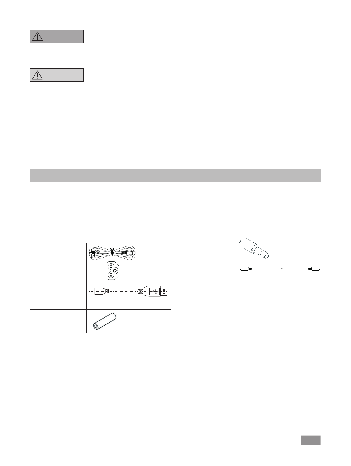
Accessories
• Safe
operation
can only be
ensured
when
working
with
accessories as described in the “Accessories” section.
• Carefully observe the operating instructions for additional
devices (e.g. rotary evaporators, vacuum controllers), with
which the vacuum pump IKA Vacstar digital is operated.
• The pressure at the gas inlet and outlet must not exceed
1100 mbar.
• Elastic elements may be pressed together under vacuum.
• Only use flexible hose lines.
• Observe your
emergency
measures for power failure and
ensure that the device is put in a safe state (see the chapter:
Commissioning, Operating mode).
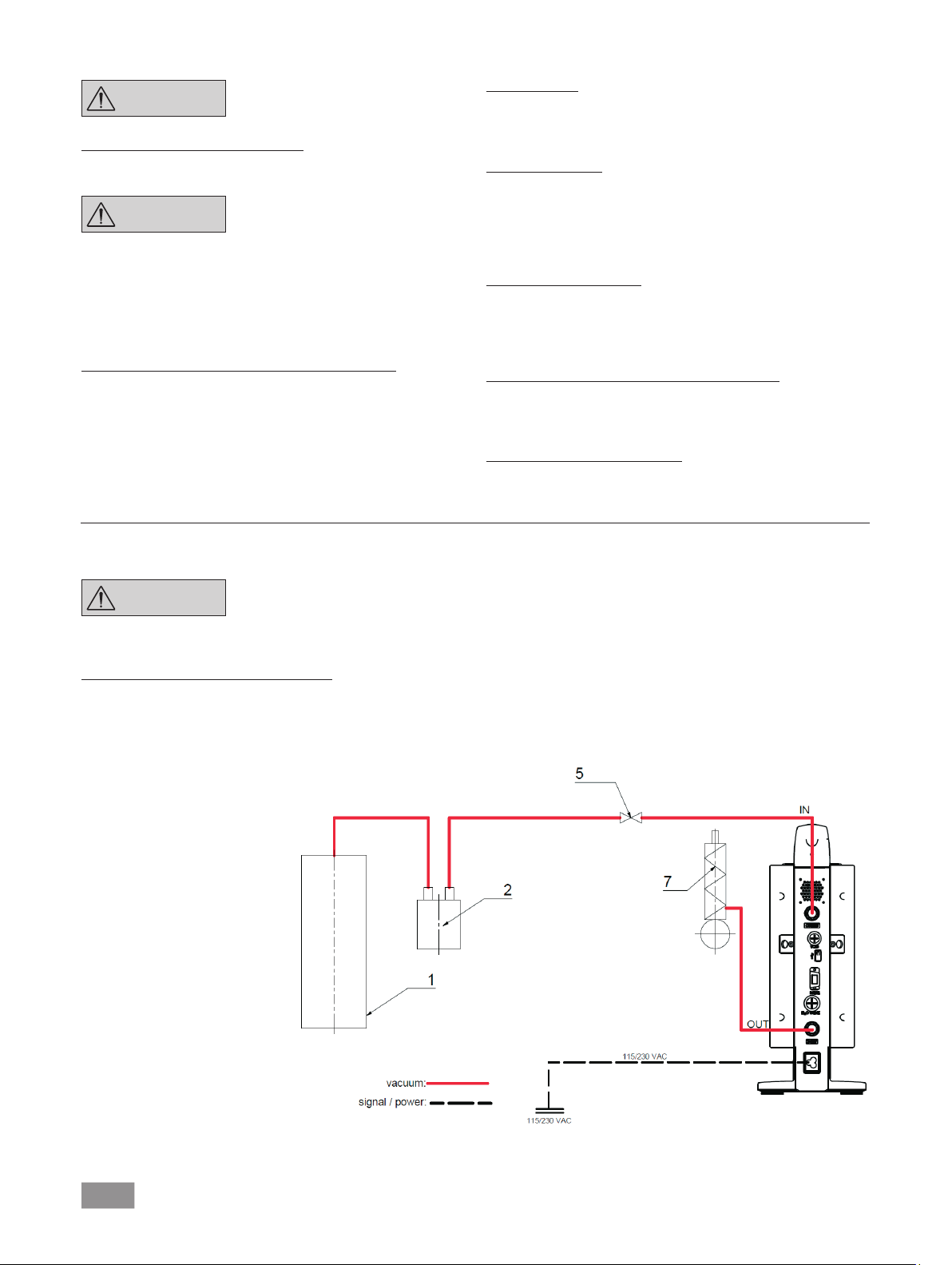
Work with the device
DANGER You can prevent the release of sol-
vent vapours into the atmosphere
using a downstream emission con-
denser.
The vacuum pump is not suitable
for use with
self-igniting
materials
,
materials that
are
flammable
without
an air
supply
, or
explosive
materials.
Do not operate the pump while it is
open. Otherwise there is a danger
of severe injuries as a hand may be
pulled into the moving parts.
WARNING
Inhaling or coming into contact
with media
such as
poisonous
liquids, gases, spray
mists,
vapours,
dusts or biological materials can
endanger the health of the user.
Ensure that all connections are
well sealed and free of leaks if you
are working with such media.
• The vacuum pump IKA Vacstar digital must only be operated
under the conditions described in the chapter “Technical data”.
• Prevent release of the materials listed above. Take measures
to protect staff and the environment.
• Pay attention to possible interactions or chemical or physical
reactions when working with media at reduced pressure and
increased temperature.
• There can be electrostatic processes between the medium
and the device which can lead to direct danger.
• Some medium may be released due to the residual leakage
rate of the device.
• Before commissioning check that all the housing parts are
present and fastened to the device.
• Do not lift the pump if the handle is loose and the handle
securing screw (E) is loose or missing!
• Only switch the pump on if the pump is standing vertically.
• Connect the hose connections (INLET-OUTLET) and interfaces
in accordance with
the
labelling on
the device and the
operating instructions.
• Ensure
that the
temperature
of the evacuated
medium
is
below
its ignition
temperature.
The pumping process
(compression)
increases the temperature
of the medium additionally.
• Ensure that vapours containing solvent can be sucked into
the pump.
• Do not use the pump to create pressure.
• Observe the permitted pressure at the inlet and outlet side;
see the chapter “Technical data”.
• The
gas
flow must only be regulated/throttled in the
suction-side line.
• Use a solenoid valve or a check valve in the suction line if
there are several load units.
• When using an emission condenser ensure that the coolant
is flowing freely.

7
Unpacking
Unpacking
• Unpack the device carefully.
• Any damage should be notified immediately to the shipping
agent (post oce, railway network or transport company).
Scope of delivery
Diaphragm vacuum pump
IKA Vacstar digital
Power supply cable
Laptop Euro
Power supply cable
Laptop GB
Power supply cable
Laptop CH
USB A - USB B cable
A
Vacuum hose 1m
Protection of the device
WARNING
Ensure that the substances used
with the device are compatible
with the materials of the device
parts that come into contact with
the
product
;
see
the
chapter
“
Product
contact parts”.
CAUTION The
specified settings on the
rating plate must coincide with the
actual power supply.
• The device is only disconnected from the power supply when
the power or device plug is removed.
• The socket for the power supply cable must be easy to access.
• Covers or parts that can be removed from the device without
tools must later be refitted to ensure safe operation, unless
anything else is connected at this point. This will prevent the
infiltration of foreign objects, liquids and other contaminants.
• Unwanted liquids
that
have entered
can be removed by
extracting air during no-load operation.
• Avoid knocks or impact to the device.
Silencer
Connecting cable MVP
10.100
Operating instructions
Warranty card
• The device must only be opened by trained, skilled personnel
(who have been authorised to do so).
• The device must not be modified without authorisation from
IKA.
• To ensure sufficient cooling for
the vacuum pump IKA
Vacstar
digital, the ventilation slits on the housing must not
be covered.
• Only use original
replacement
parts for
maintenance
to
ensure that the device works reliably.
• Watch out for
water condensation
inside and outside the
device. Warm up the device first, if it has been brought in
from a cold environment.
• Never fasten the vaccum pump over a heating bath.
• Ensure that no solids and/or liquids can enter the diaphragm
of the vacuum pump IKA Vacstar digital through the suction
line of the pump. This damages the diaphragm and other
internal parts of the pump. This reduces delivery capacity and
the final pressure can no longer be achieved. Deposits may
be produced in the interior, reducing service life and causing
leaks.

8
Use
WARNING
The device must not be used for:
- evacuating biological habitats,
-
evacuating explosive, corrosive
or similar gases,
- throughput/use of liquids
The device is not suitable for:
- pumping up objects
- pumping liquids
-use in potentially explosive
atmospheres
- underwater
- underground
The laboratory diaphragm vacuum pump
IKA Vacstar digital is
used
together with other laboratory devices to create a vacuum.
For specific vacuum control, an additional vacuum controller IKA
VC 10 or IKA rotary evaporator RV 10 auto is required.
Correct use
Useful information
DANGER You can
prevent the release
of
solvent vapours into
the atmosphere
using
a downstream emission
condenser.
CAUTION Special care must be taken when
working with gas
mixtures
that
include condensable gases (e.g.
solvents). If diaphragm pumps are
used with
such
gases they
condense
in the pump’s air flow. This leads
to a build-up of pressure in the
vacuum chamber,
which in turn
influences the effectiveness and
service life of the diaphragms and
valves.
If liquid or condensate enters the
vacuum chambers, the specified
minimum working pressure is no
longer achieved.
To
protect
the inner valves and
diaphragms against liquid, use an
upstream condensate separator,
such as a Woulff bottle.
CAUTION It is generally recommended that
you run the pump with no load at
the end of the
process (no-load
operation, approx. 3 up to max. 5
minutes) to dispel any residues in
the pump.
If applicable, vent the recipient.
To do this, remove the suction line
during manual operation.
NOTE Observe the operating instructions
of the relevant devices.
Diaphragm vacuum pumps are oscillating displacement pumps.
The diaphragms expand the volume of the vacuum chamber to
produce an underpressure, which sucks air into the chamber. The
air is then pressed out of the vacuum chamber by subsequent
compression. Changes between the inlet and outlet are controlled
by diaphragm valves.
The physical unit for pressure is 1 Pascal [Pa].
However people often still use the unit millibar [mbar] colloquially.
1 mbar = 100 Pa
1 bar = 105Pa
1 Pa = 10-5 bar
1 Pa = 0.01 mbar
Area of use (only indoors)
The device is suitable for use in
residential
areas and all other areas.
The safety of the user cannot be ensured:
• if the device is used in conjunctions with accessories not
made or recommended by the manufacturer!
Standalone operation
The vacuum pump can be operated without a controller.
The delivery
capacity
can be set using the adjustable speed.
Generally
speaking, the smaller the volume to be evacuated, the lower the
speed should be. The final pressure is not controlled.
Operation with accessories
Along with the accessories recommended by IKA, the vacuum
pump
IKA Vacstar digital
is suitable for controlled evacuation to a
specified final pressure e.g. for operating an IKA rotary evaporator.
It can also be used for classical separation, filtration or drying in
the laboratory.
With an appropriate vacuum controller
(e.g. VC 10)
or with a rotary
evaporator (e.g. RV 10 auto), the
Vacstar digital
can be operated
automatically, for automatic boiling point detection, scheduled
pressure-time
curves or programs from the solvent library, for example.
Intended use: Tabletop device
• if modifications are made to the device or parts of the device
by third parties!
• if the device is
operated in contravention of the safety
instructions!

9
Two-position control
When the target value is reached, the suction line is interrupted.
Due to the small delay between the times when the pressure value
is detected, when comparison is made with the target value, when
a vacuum valve is switched off and when the suction line of the
vacuum-producing system are switched off, it is easy to go below
the set target value. If the pressure in the system goes up again
due to a natural leakage rate, the suction line valve opens.
Schematic view of two-position vacuum control
Analogue speed control
With this control, the speed of the pump,
and therefore its
suction
power, is reduced the closer the measured pressure reaches the
target value. Once the target value is reached,
the pump only
operates according to the leakage rate of the system. This enables
quiet functioning, precise vacuum control and a long service life
for the
moving pump parts
. Exact
automatic boiling
point
recognition
is
possible with this type of control, meaning that the system reaches
and keeps the solvent at its boiling point in automatic mode.
Schematic view of speed vacuum control
t
mbar
t
mbar
A distinction
is made
between different ranges
in vacuum
technology.
Rough vacuum: 105to 10² Pa (1000 to 1 mbar)
Fine vacuum: 10² to 10-1 Pa (1 to 10-3 mbar)
High vacuum: 10-1 to 10-5 Pa (10-3 to 10-7 mbar)
Ultra high vacuum < 10-5 Pa (< 10-7 mbar)
The periodic movements of the diaphragms create a vacuum at
the pump inlet. Diaphragm vacuum pumps work with a rough
vacuum of up to 102Pa. Lower pressures cannot be achieved with
these pumps.
To create fine, high and ultra high vacuums, oil-sealed vacuum
pumps, screw pumps, diffusion pumps or turbomolecular pumps
must be used, for example. Diaphragm vacuum pumps are often
used as pumps for the preliminary stage in these contexts.
Compressing and releasing the pressure on air creates a noise. The
pump is quieter the less air is transported. This means that there
is less operating noise during normal operation if the pressure is
reduced.
A fitted exhaust hose with a sound absorber can also be used to
reduce noise.
In automatic operation with controlled speed the pump reduces
its speed when it reaches the target value. If the leakage rate in the
entire system is low enough, the speed may even be set to “zero”.
When combined with the vacuum controller VC 10 or the
rotary
evaporator with integrated vacuum controller RV 10 auto,
the
pump can
also
be used for
“two-position control” (valve-controlled)
or “analogue speed control” of the vacuum.
Setting up
NOTE Ensure that you follow the general
rule
, that
the
recipient
(load/vacuum
container/glass condenser) should
always
be connected to
the suction
line at its
highest
point.
This reduces
the risk of liquids entering the vacuum
pump.
Liquid in the pump chambers
makes the pump properties worse.
Connect the hose
connections
(INLET/OUTLET) and interfaces in
accordance with
the labelling on the
pump and the
operating instructions.
The connections are barbed hose connectors
. Ensure that the
hoses have hose clips if applicable.
Lay the hoses in such a way that no condensate can flow into the
pump.
Ensure that the air can enter the ventilation slit (H) unhindered.
Install a condensate separator (e.g. a Woulff bottle) in the suction
line before the intake spigot of the pump to protect against water
coming in.
If solvent vapours are sucked in, an emission condenser (accessory)
after the pump helps to condense it, and prevents it being released
into the atmosphere.

10
Configuration
NOTE
Observe the operating instructions
for the devices.
Two-position control:
IKA Vacstar digital in standalone operation
Vacuum created without a controller through simple suction, no
vacuum target value control possible.
The pump speed can be changed by manually setting the speed
using the rotating/pressing knob (C) of the vaccum pump.Manual
1 Recipient (load, e.g. rotary
evaporator, reactor)
2 Vacuum separator (e.g. Woulff
bottle)
5 Vacuum valve/ball valve
7 Emission condenser
Connection of interfaces
NOTE Observe the relevant connections
(see Fig. 1).
O: Hose connection d= 8 mm OUTLET
Link this connection to the emission condenser with a vacuum
hose, or fit a sound absorber to the end.
NOTE
Put the end of the hose in the
extractor hood!
Check there is a free outlet on the
pressurised side!
Do not use a throttle on the
pressurised side
and do not close
the outlet! Connect the exhaust
line to this connection.
K: Connection for vacuum controller VC 10 (Mini DIN)
You can connect the vacuum pump and the vacuum controller
VC 10 or the
rotary evaporator RV10 auto
with the analogue
connection cable
MVP 10.100
for
precise speed-controlled
vacuum control.
The vacuum controller detects the pump and switches to
speed-vacuum control mode. Two-position control is deactivated.
L: USB interface
Connect the vacuum pump IKA Vacstar digital to a PC with a USB
A - USB B cable. Any device software updates can be loaded using
the IKA FUT software tool.
M: RS 232 interface
You can connect the IKA Vacstar digital vacuum pump to a PC
using an RS 232 interface cable. The pump can be operated in
conjunction with other devices with
labworldsoft®laboratory
device software.
For
further
information
see the chapter “Interfaces
and outputs”.
N: Water valve connection
Connect the optional water
throttle
valve RV 10.5001
to the
diaphragm vacuum pump.
The water
flow to the emission
condensor is controlled using the water valve. The valve is opened
as soon as the pump is switched on.
I: Hose connection for suction line d= 8 mm INLET
Connect the suction line to this connection.
Link this connection to the recipient (rotary evaporator condenser,
laboratory reacor etc.) with a vacuum hose.
P: Power supply cable connection
Check that the voltage information on the rating plate matches
your mains supply. Connect
the
power supply
cable
to supply
electricity.
activation of the vacuum valve or ball valve.
Rough vacuum control is possible, for example, with the vacuum
control valves VCV 1 and VCV 2, by mixing in air from outside.

11
24 VDC
115/230 V
IKA Vacstar digital with vacuum controller VC 10
NOTE
Cannot
be operated with optional
water valve RV 10.5001 in conjunction
with VC 2.4.
Refer to the operating instructions
for the vacuum controller VC 10!
When the target value is reached, the suction line is closed by the
vacuum valve integrated in the VC 10. The pump speed can be
changed by manually setting the speed.
When using the optional pump cut-out unit
VC 2.4 (ref. 6) the pump is switched off when the target value is
reached (operating mode B).
This
device configuration
is also
possible without
the pump
cut-out unit VC 2.4. The pump runs on. For good control, the
pump should be operated at a low speed.
1 Recipient (load, e.g. rotary
evaporator, reactor)
2 Vacuum separator (e.g. Woulff
bottle)
3 Vent valve
4 Pressure sensor
5 Vacuum valve/ball valve
6 Pump cut-out unit VC 2.4
7 Emission condenser
Speed regulation
IKA Vacstar digital with vacuum controller VC 10 or rotary
evaporator
RV 10 auto
NOTE
Observe the operating instructions
for the devices.
Automatc setting of the operating mode “Speed regulation” as
soon as the
analogue connecting cable
MVP 10.100 (ref. 8)
connects the pump
with the vacuum controller or rotary evaporator.
When the target value is reached, the pump speed is
auto-
matically
reduced
to
a minimum of “0 rpm”.
Once the target
value is reached, the pump applies
suction according to the
leakage
rate of the vacuum system. Automatic boiling point recognition
is possible.
1 Recipient (load, e.g. rotary
evaporator, reactor)
2 Vacuum separator (e.g.
Woulff bottle)
7 Emission condenser
8 Analogue connecting cable
MVP 10.100

12
Commissioning
NOTE
Observe the operating instructions
for the devices.
Check if the voltage specified on the type plate matches the avail-
able mains voltage. If these conditions are met, the device is ready
for operation when it is plugged in to the mains.
The socket used must be earthed
(grounded contact).
Switching on with several interfaces
If the pump is operated via the analogue connecting cable MVP
10.100 with the vacuum controller VC 10 or the rotary evaporator
RV 10 auto, “VC 10” is shown on the display.
If the vacuum controller is connected to a PC, “PC” is shown on
the display (B).
Switching off
Switch off the device using the main switch (D).
Unplug the appliance from the
mains socket to disconnect it from
the mains.
Otherwise safe operation is not guaranteed or the device may be
damaged.
Observe the ambient conditions indicated under “Technical data”.
Switching on
1. Switch on the device using the main switch (D). All display
sements are shown to enable a visual check.
2. Software version number display (e.g. vers. 1.00).
3. Operating mode display (A; B). (Factory setting: Operating
mode A)
The operating mode can be changed when you switch on the
device.
Operating mode A:
In this operating mode, the set target value is not saved when
the current run comes to an end or the device is switched off.
No automatic restart after mains power is cut off.
Operating mode B:
In this operating mode, the set target value is saved when the
current run comes to an end or the device is switched off, and
the value can be changed.
Operating mode B is required particularly in combination with
the pump cut-out unit VC 2.4.
Automatic restart after mains power is cut off.
Changing operating mode:
1. Press the rotating/pressing knob (C) and switch on the
device at the main switch (D) at the same time to change
between the two operating modes.
In standalone operation or two-position operation in combination
with the vacuum controller VC 10 the target speed can be set by
turning the rotating/pressing knob (C). Push to start the pump and
push again to stop it. A flashing light on the display (B) indicates
when the device is running.

13
Interfaces and outputs
NOTE
Please comply with
the system
requirements together with the
operating instructions and help
section
included with
the software.
The device can be operated in “Remote” mode via an RS232 or
USB interface using the laboratory software labworldsoft®. The RS
232 interface (M) at the back of the device is fitted with a 9-pole
SUB-D jack which can be connected to a PC. The pins are assigned
serial signals.
USB Interface
The Universal Serial Bus (USB) is a serial bus system which allows
the device to be connected to the PC. Devices that support USB
can be connected to each other whilst
they are running
(hot
plugging) and provide automatic
recognition of the
connected
devices and their properties.
Use the
USB interface
in conjunction with
labworldsoft®
for
operation in “Remote” mode and for updating the firmware using
the “Firmware update tool”.
Installation
Before the device is connected with the PC using the USB data
cable, the USB driver must be installed.
The USB driver can be downloaded from the website:
Serial interface RS 232 (V 24)
Configuration:
• The functions of the interface circuit between the device and
the automation system
are a selection from the signals specified
in the EIA standard RS232 as per DIN 66020 Part 1.
• Standard RS 232, corresponding to DIN 66259 Part 1 is valid
for the electric characteristics of the
interface
circuits and
assignment of signal states.
• Transmission process: Asynchronous character transmission
in start-stop operation.
• Transmission type: Full duplex.
• Character format: Character composition according to data
format in DIN 66022 for start-stop operation. 1 start bit, 7
character bits, 1 parity bit (even), 1 stop bit.
• Transmission speed: 9600 Bits/s.
• Data flow control: none
• Access method: Data transmission from the device to the
computer only occurs after a request from the computer.
Command syntax and format
The following points should be noted for the instruction set:
• Commands are generally sent from the computer (master) to
the device (slave).
• The device only responds to requests from the computer.
Even error messages are not send spontaneously from the
device to the computer (automation system).
• The commands are transmitted in captial letters.
• Commands
and
parameters,
as well as consecutive parameters,
must be separated by at least one space (code: hex 0x20).
• Each individual command (including parameters and data)
and all responses are completed with CRLF (code: hex 0x20
hex 0x0d hex 0x0A) and can have a maximum length of 50
characters.
• The dot is used for decimal separators in a floating-point val-
ue (code: hex 0x2E).
The
details
given
above generally comply
with the
recommendations
of NAMUR (NAMUR recommendations for the design of electrical
plug-in connectors for analogue and digital signals in laboratory
MSR devices. Rev. 1.1).
The NAMUR commands and the additional IKA-specific
commands are only used as low-level
commands for communication
between the device and the PC. With an appropriate terminal or
communication program, these commands can
be transmitted
directly to the device.
NAMUR commands Function
IN_NAME Read device name
IN_PV_4 Read current speed value
IN_SP_4 Read rated speed value
OUT_SP_4 Adjust the rated speed value
START_4 Start evacuation
STOP_4 Stop evacuation
RESET Switch to normal operating mode
OUT_NAME Set device name
OUT_SP_42@n Setting WD safety limit speed with
set value echo
OUT_WD1@m Watchdog mode 1
OUT_WD2@m Watchdog mode 2
“Watchdog” functions; monitoring of the serial data flow
If, once this function has been activated (see NAMUR commands),
there is no retransmission of the command from the computer
within the set time (“watchdog time”), the Evacuation function is
switched off in accordance with the set “watchdog” mode or is
returned to previously set target values. The data transmission may
be interrupted by, for example, a crash in the operating system,
a power failure in the PC or an issue with the connection cable
between the computer and the device.
“Watchdog” mode 1
If event WD1 should occur, the evacuation function is switched
off and ER2 is displayed. Set watchdog time to m (20- 1,500)
seconds, with watchdog time echo. This command launches the
watchdog function
and must be transmitted within the
set watchdog
time.
“Watchdog” mode 2
If there is an interruption in data communications (longer than the
set watchdog time), the speed target value is changed to the set
WD safety speed limit. The warning PC 2 is displayed. The WD2
event can be reset with
OUT_WD2@0 -
this also stops
the watchdog
function.
Set watchdog time to m (20 - 1,500) seconds, with watchdog
time echo. This command launches the watchdog function and
must be transmitted within the set watchdog time.

14
Accessories: PC 1.1 cable (device to PC)
Required for connecting the 9-pin socket to a PC.
Connecting cable MVP 10.100
Required for connecting VC 10 and RV 10 auto with the diaphragm vacuum pump
IKA Vacstar digital
(speed operation).
Fig. 10
Fig. 12
USB A - USB B cable
Required for connecting the USB interface (L) to a PC.
USB B USB A
A
Fig. 11
Maintenance and cleaning
The device is maintenance-free. However it is subject to natural
wear and tear on parts and their statistical failure rate.
Unplug from the mains before clean-
ing.
Only clean the IKA device using these IKA-approved cleaning
agents:
Dirt Cleaning agent
Dyes Isopropyl alcohol
Building materials Water containing detergent, isopropanol
Cosmetics Water containing detergent, isopropanol
Food Water containing detergent
Fuels Water containing detergent
Other materials Please ask IKA
• Wear protective gloves when cleaning the devices.
• Do not place electrical appliances into the cleaning agents for
cleaning purposes.
• Ensure no liquid enters the device during cleaning.
• Please consult with IKA before using any cleaning
or
decontamination methods not specifically recommended.
Ordering spare parts
When ordering spare parts,
please make sure
to indicate the
following:
• Device type
• Device manufacturing number; see rating plate
• Reference number and description of spare part; see spare
part diagram and list at www.ika.de.
Repairs
Please only send devices in for repair that have been
cleaned and are free of materials which might present
health hazards.
For this, use the “certificate of compliance” form which you
can obtain from IKA or can download a version for printing from
the IKA website www.ika.de
If your appliance requires repair, return it in its original packaging.
Storage packaging is not sucient. also use appropriate transport
packaging.
1
2 RxD
3 TxD
4
5 GND
6
7 RTS
8 CTS
9
1
RxD 2
TxD 3
4
GND 5
6
RTS 7
CTS 8
9
PC
1
2
3
4
5
6
7
8
9
9
8
7
6
5
4
3
2
1

15
Error codes
If an error occurs, this is shown in an error on the display (B), e.g. Error 4.
Proceed as follows:
• Switch the device off on the device switch,
• Take corrective measure,
• Switch device back on.
Error Cause Reason Solution
Error 3 Overheat The pump does not run Switch off the pump, disconnect it from the mains, let
it cool down.
Error 4 Motor blocked/overload The pump does not run Switch off the pump, disconnect it from the mains
Let the pump cool down.
Ventilate the vacuum system to normal pressure.
Error 8 Hall sensor defective The pump does not run Service
Error 9 BLP self-test/EEPROM error The pump does not run Service
No display Pump diaphragm defective Minimum pressure and suction
rate are not achieved
Service
Request a maintenance kit
No display Diaphragm valve defective Minimum pressure and suction
rate are not achieved
Service
Request a maintenance kit
No display Liquid in the pump chambers Minimum pressure and suction
rate are not achieved
Let the pump run dry (no-load operation)
In the event that the fault cannot be eliminated using the measures described or another error code is displayed:
• Please contact the Service Department,
• Send the device and a brief description of the fault.
Accessories
• Vacuum controller IKA VC 10
• Vacuum control valve IKA VCV 1 and VCV 2
• Check valve IKA VC 10.300
• Vacuum hose IKA VH.SI.8
• PC 1.1 cable (RS 232)
Product contact parts
Name Material
Connection spigot PPS
Connection piece PPS
Distributor PPS
Head piece PPS
Diaphragm valve FFPM
Diaphragm NBR/PTFE
Clamp PPS
• Maintenance kit
• Vacuum safety emission condenser VSE 1
• Woulff bottle/water valve set VSW1
For further accessories see www.ika.de

16
Technical data
Base unit Value
Delivery capacity max. m³/h 1.32
Delivery capacity max. L/min 22
Final pressure mbar 2
Suction steps 4
Cylinder 4
Connection diameter suction side mm 8
Connection diameter pressure side mm 8
Gas ballast valve no
Inlet pressure min. mbar 2
Inlet pressure max. mbar 1030
Boiling point recognition no
Solvent library no
Two-position control yes
Analogue speed-vacuum control yes
Speed setting option rotating/pressing knob
Speed min. rpm 285
Speed max. rpm 1200
Display LED
Vacuum sensor no
Vent valve no
Condensate separator no
Emission condenser no
Volume at minimum pressure dB(A) 54
Product contact material PTFE, FFPM, PPS, NBR
Housing material Cast alu, coated
Appropriate for clean room no
Explosion-proof no
Width mm 150
Depth mm 370
Height mm 375
Weight kg 11.5
Permitted ambient temperature min. °C 5
Permitted ambient temperature max. °C 40
Permitted relative humidity % 80
Protection class according to DIN EN 60529 IP 20
RS 232 interface yes
USB interface yes
Analogue output no
Voltage V 100-240
Frequency Hz 50/60
Power consumption W130
Standby power consumption W1.5
DC VDC 24

17
Base unit Value
Protection class II
Overvoltage category I
Degree of contamination 1
Use above max. sea level m2000
Firmware update yes
Subject to technical changes

18

19
Traduction
Page
Structure de l’appareil ............................................................................................................................................................... 2/3
Déclaration de conformité......................................................................................................................................................... 19
Explication des symboles........................................................................................................................................................... 19
Garantie.................................................................................................................................................................................... 19
Consignes de sécurité ............................................................................................................................................................... 20
Déballage ................................................................................................................................................................................. 21
Utilisation conforme.................................................................................................................................................................. 22
Informations utiles .................................................................................................................................................................... 22
Installation................................................................................................................................................................................ 23
Mise en service ......................................................................................................................................................................... 24
Interfaces et sorties................................................................................................................................................................... 27
Entretien et nettoyage............................................................................................................................................................... 28
Messages d’erreurs ................................................................................................................................................................... 29
Accessoires ............................................................................................................................................................................... 29
Pièces en contact avec le produit .............................................................................................................................................. 29
Caractéristiques techniques....................................................................................................................................................... 30
Table des matières
Nous déclarons, sous notre seule responsabilité, que ce produit est conforme aux dispositions des directives 2014/35/UE, 2006/42/CE,
2014/30/UE e
t 2011/65/UE ainsi qu’aux normes et documents normatifs suivants:
EN 61010-1, EN
60529
, EN 61326-
1 et EN ISO 12100.
Déclaration de conformité
Explication des symboles
Conformément aux conditions de vente et de livraison d’IKA, la
garantie s’étend sur une période de 24 mois. En cas de demande
de garantie, s’adresser au distributeur. Il est également possible
d’expédier l’appareil accompagné de la facture et de la raison de
la réclamation directement à notre usine. Les frais de port sont à
la charge du client.
Garantie
La garantie ne s’étend pas aux pièces d’usure et n’est pas valable
pour les erreurs causées par une manipulation non conforme, un
entretien et une maintenance insusants ou le non-respect des
instructions du présent mode d’emploi.
FR
Situation (extrêmement) dangereuse dans laquelle le non-respect des consignes de sécurité peut causer la
mort ou des blessures graves.
Situation dangereuse dans laquelle le non-respect des consignes de sécurité peut causer la mort ou des
blessures graves.
Situation dangereuse dans laquelle le non-respect des prescriptions de sécurité peut causer des blessures
graves.
Indique par exemple les actions qui peuvent conduire à des dommages m
atéri
els.
DANGER
AVERTISSEMENT
REMARQUE
PRUDENCE

20
Consignes de sécurité
Pour votre sécurité
REMARQUE Lisez entièrement le mode
d’emploi
avant la mise
en
service et
respectez
les consignes de sécurité.
• Conservez
le
mode d’emploi
de manière à ce qu’il soit accessible
à tous.
• Veillez à
ce que seul un
personnel formé travaille avec
l’appareil.
• Respectez les consignes de sécurité, les directives, ainsi que
les mesures de prévention des accidents.
• L’appareil et ses
pièces ne doivent pas être utilisés sur les
personnes ou les animaux.
DANGER
Portez votre équipement de protection
personnelle en fonction de la
classe de
danger du milieu à traiter,
en raison du danger présenté par
les projections de liquides et les
dégagements de gaz toxiques ou
inflammables!
• Ne soumettez pas au vide des parties du corps de personnes
ou d’animaux.
• N’utilisez pas l’appareil sous l’eau ou sous terre.
Structure de l’appareil
DANGER
La pompe à vide IKA Vacstar digital
n’est pas conçue pour être installée
dans les zones à atmosphère explosive.
• Mettez l’appareil en place conformément au chapitre «Instal-
lation», et raccordez les câbles et les interfaces comme décrit.
• Placez l’appareil sur une surface stable, plane et non inflam-
mable.
• Ne travaillez jamais
avec un appareil mal raccordé ou dé-
fectueux.
• Placez la pompe à vide dans une hotte de laboratoire adaptée
et fonctionnelle ou raccordez-la à une conduite d’évacuation
de la fumée. Veillez à ne pas couder la conduite d’évacua-
tion! La longueur de la conduite d’évacuation ne doit pas
dépasser 2m!
• Évitez la formation de mélanges explosibles, raccordez éven-
tuellement un gaz inerte pour la ventilation et/ou pour la di-
lution.
Accessoires
• La sécurité du travail n’est garantie qu’en utilisant les
accessoires décrits au chapitre «Accessoires».
• Respectez attentivement
le mode d’emploi des appareils
additionnels (p. ex. évaporateur rotatif, contrôleur de vide)
avec lesquels la pompe à vide
IKA Vacstar digital
fonctionne.
• La pression à l’entrée
et à la sortie du gaz ne doit pas dépasser
1100mbar.
• Les éléments élastiques peuvent être comprimés sous l’effet
du vide.
• Ut
ilisez exclusivement des conduites flexibles.
• En cas de panne électrique, suivez vos mesures d’urgence et
assurez-vous de placer l’installation dans un état sûr (voir le
chapitre Mise en service
, Mode de fonctionnement).
Utilisation de l’appareil
DANGER La sortie de vapeurs de solvants
dans l’atmosphère peut être évitée
avec un condenseur d’évacuation
placé en aval.
La pompe à vide n’est pas conçue
pour une utilisation avec les
substances auto-inflammables,
les
substances inflammables
en l’absence d’apport d’air ou les
substances explosives.
Ne faites jamais fonctionner la
pompe quand elle
est ouverte.
Sinon, il y a un risque de blessures
graves en cas d’insertion de la
main dans des pièces rotatives!
AVERTISSEMENT
L’inhalation ou le contact avec des
milieux tels que les liquides
toxiques
, les gaz, les brouillards de
pulvérisation, les vapeurs, les
poussières ou les substances
biologiques peut être dangereux
pour la santé de l’utilisateur.
Assurez-vous
de l’étanchéité de
tous les raccords lors de
l’utilisation
de ces milieux.
• La pompe à vide IKA Vacstar digital doit être exploitée exclu-
sivement dans les conditions décrites au chapitre «Caracté-
ristiques techniques».
• Empêcher le dégagement des substances susmentionnées.
Prenez des mesures de protection pour le personnel et l’en-
vironnement.
• Tenez compte des éventuelles interactions ou réactions
chimiques ou physiques, lors de la manipulation de milieux
sous pression réduite et température accrue.
• Des processus électrostatiques peuvent se produire entre le
milieu et l’appareil et engendrer un danger.
• En raison du taux de fuite résiduel de l’appareil, un relargage
du milieu peut se produire.
• Avant la mise en service, vérifier que toutes les pièces du car-
ter sont présentes et fixées sur l’appareil.
• Ne soulevez pas la pompe si la poignée est desserrée et si la
vis de sécurité de la poignée (E) est dévissée ou manquante!
• Activez la pompe uniquement si la pompe est à la verticale.
• Reliez les raccords de flexibles (INLET-OUTLET) et les inter-
faces conformément aux inscriptions sur l’appareil et aux in-
dications du mode d’emploi.
• Assurez-vous que la température du milieu évacué se trouve
sous la température d’inflammation. Le processus de pom-
page (compactage) fait encore monter la température du
milieu.
Other manuals for Vacstar control
4
Table of contents
Languages:
Other IKA Water Pump manuals
Popular Water Pump manuals by other brands

CRANE PUMPS & SYSTEMS
CRANE PUMPS & SYSTEMS Deming 3021 Series Installation, operation and maintenance manual

Pentair
Pentair Nocchi MCP 4 Use and maintenance manual

CET
CET SM-PFP-25hp-DSL-MR instruction manual

Graco
Graco LubePro H1900 instructions

Liberty Pumps
Liberty Pumps Omnivore 2448 Series installation manual

Graco
Graco 24V672 repair parts

Daiwha
Daiwha DI-6000 user manual

Pentair
Pentair 6TS 6" Installation and operation manual

Oase
Oase ProMax Pressure Well 6500/10 operating instructions

Bosch
Bosch ECP 160 installation manual

Watson Marlow Pumps
Watson Marlow Pumps 730 S Installation, operating and maintenance manual

UDOR
UDOR ZETA 70 Series manual