manuals.online logo
Brands
  1. Home
  2. •
  3. Brands
  4. •
  5. Ikelite
  6. •
  7. Camera Accessories
  8. •
  9. Ikelite SLR-DC Housing User manual

Ikelite SLR-DC Housing User manual

2
Strobe
Mount
Rubber
Handle
Quick-Release
Strobe
Mount
Gear Sleeve
Drive Gear
Zoom
Control
Lid Snap
Mode
Dial
Lens
Release
Main Dial
Meter/Flash
Drive Mode
AF/WB Mode
Illuminator
Lid
Snap
Shutter
Release
AE/FL
Lock
Port Lock
Aluminum Tray
Port
Opening
IKELITE
Quick
Release
Button
External Strobe Connector
and Waterproof Cap
Viewfinder Port
Shutter
Release
[D] Playback
[E] Erase
[F] ON/Off
[G] Set
[H] Quick Control
[I] AF Point
A
B
C
D
E
F
GH
J
I
Lens
Release
Zoom AE/FE Lock
[A] Menu
[B] Info
[C] Jump
[J] eTTL Mode/Compensation
FRO T VIEW
BACK VIEW
3
SIDE VIEW
Gear
Sleeve
Port
O'ring
Optional
Port
Lid
Snap
Shutter
Release
AE/AF Lock
Back O’ring
Main Dial
Camera Tray
Camera
Mounting
Bolt
OOppeenniinngg tthhee HHoouussiinngg
Lid Snaps have a LLoocckk. To open, push Lid Snap Lock forward and
lift as shown. Keep pressure on the Lid Snap so it does not fly
open quickly.
Some lid snaps have a lot of spring tension once they go over
center, so have a firm grip on the lid snap. Lid Snaps may be
opened one at a time.
Lift
Push Forward
Lid Snap Lock
4
IInniittiiaall CCaammeerraa SSeettuupp
- Insert a fully charged battery.
- Insert memory card (1GB or greater capacity recommended).
- Set the mode dial to “M” manual.
- Set shutter speed to 1/60th second or 1/125th second for fast
moving subjects.
- Set aperture to F8 for general photography or F22 for macro
photography (close-ups).
- Set Quality to highest jpeg setting “L” or RAW.
- Set ISO to 100 and Meter to “center-weighted”.
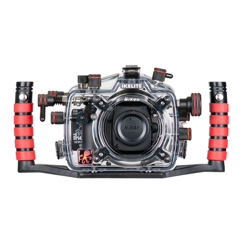
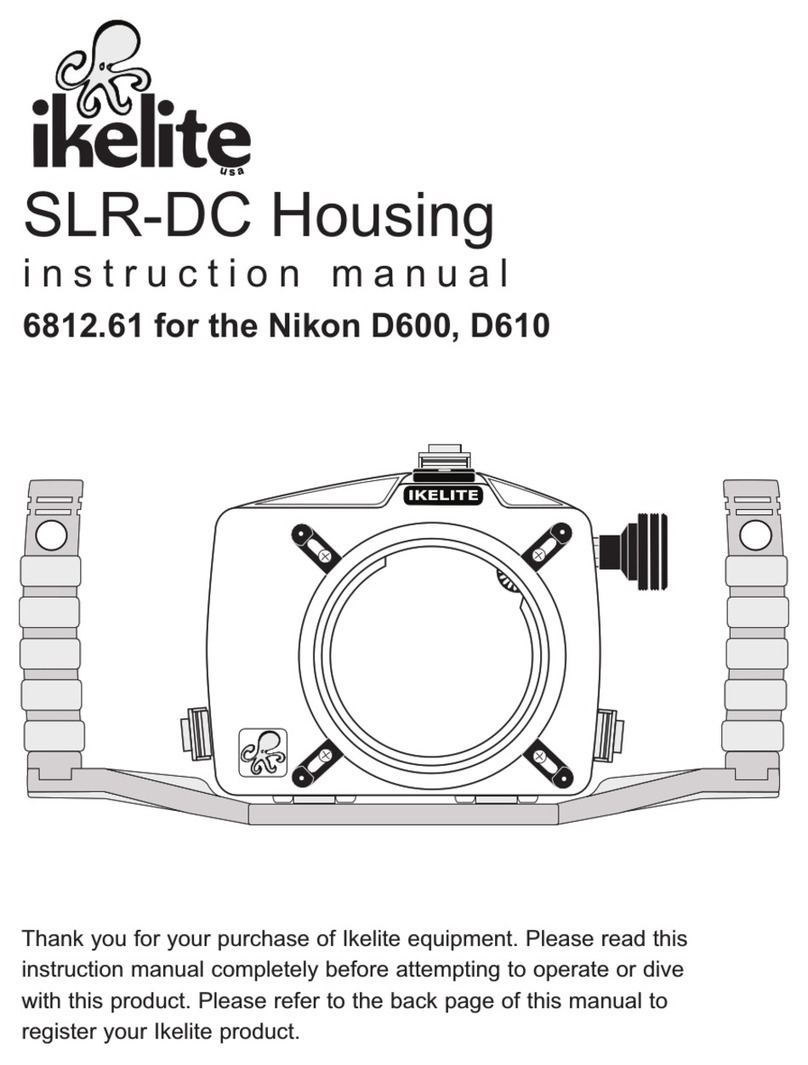
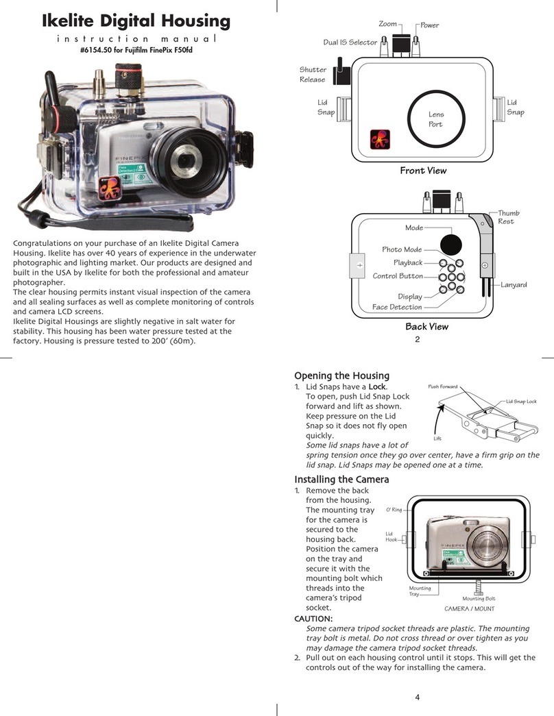
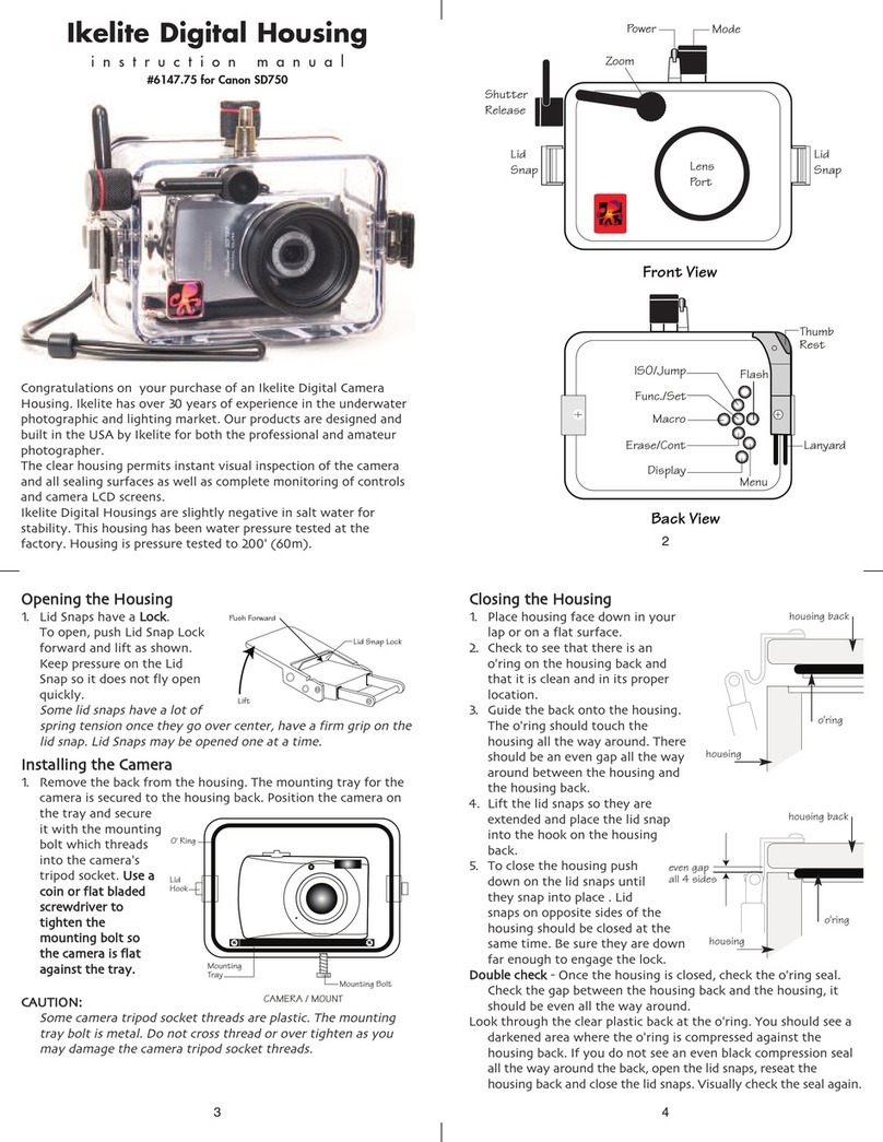
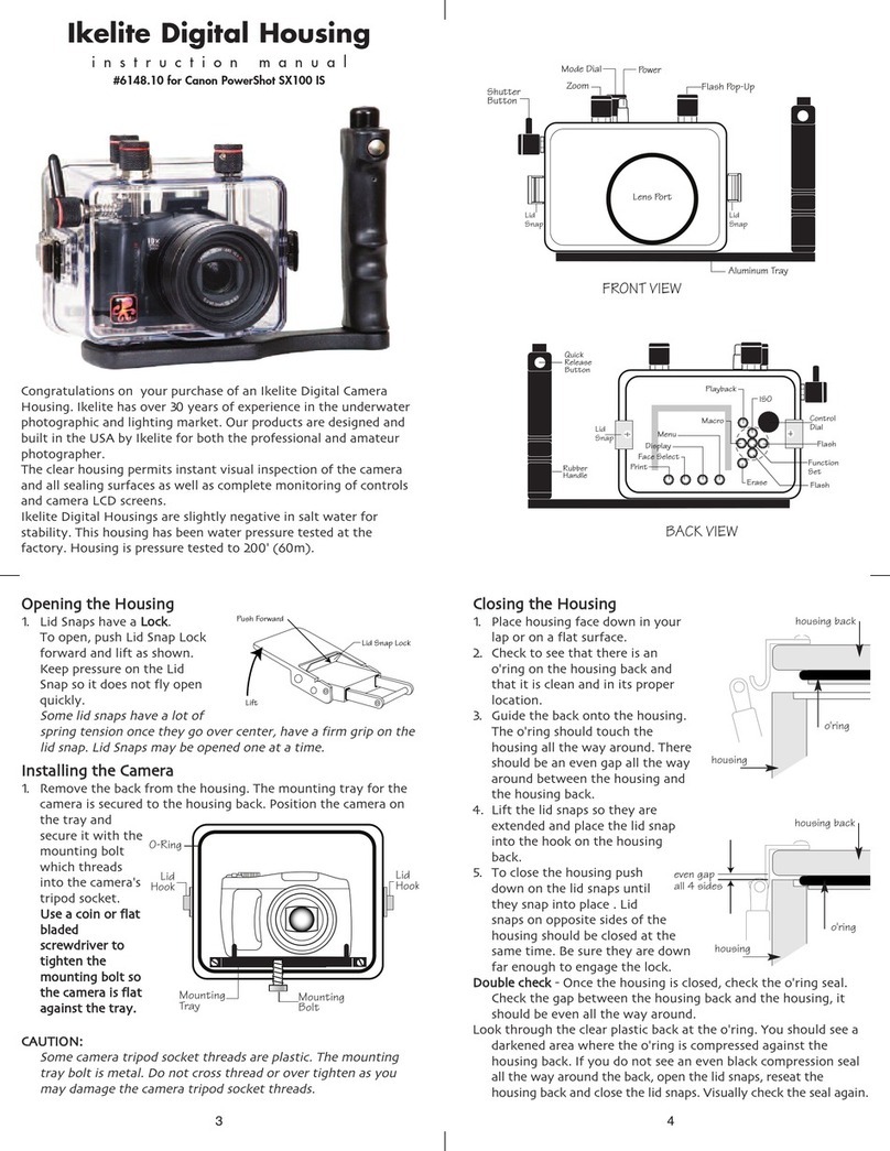
Ikelite SLR-DC Housing
i n s t r u c t i o n m a n u a l
#6871.05 for Canon EOS 5D
Congratulations on your purchase of an Ikelite Digital Camera
Housing. Ikelite has over 45 years of experience in the underwater
photographic and lighting market. Our products are designed and
built in the USA by Ikelite for both the professional and amateur
photographer.
The clear housing permits instant visual inspection of the camera
and all sealing surfaces as well as complete monitoring of controls
and camera LCD screens.
Ikelite Digital Housings are slightly negative in salt water for
stability. This housing has been water pressure tested at the
factory. Housing is pressure tested and warranted to 200’ (60m).
IKELITE
6
FFllaasshh CCoonnnneeccttiioonn ffoorr EExxtteerrnnaall SSttrroobbeess
When using an external strobe, connect the housing hotshoe
connector. Slide the connector into the hotshoe mount on the
camera from the back of the camera as shown. Slide the
connector
forward until
it stops. This
can be done
before or after
the camera is
secured with
the mounting
bolt.
External Strobe Connector
Waterproof Cap
O'ring
Housing Back
Camera
Hot Shoe
Connector
C
Ca
au
ut
ti
io
on
n:
:
Do not remove the External Strobe Connector’s waterproof cap
unless an external sync cord is going to be plugged in. Do not
remove waterproof cap or sync cord underwater.
I
In
ns
st
ta
al
ll
li
in
ng
g C
Ca
am
me
er
ra
a i
in
n H
Ho
ou
us
si
in
ng
g
Before installing the camera, pull out on the controls in the front
section of the housing. This will allow the camera to slide in more
easily. Once the camera is installed and the lid snaps have been
closed, return the controls to their operating position.
CClloossiinngg tthhee HHoouussiinngg
1. Place housing face down in your lap.
2. Check to see that there is an o’ring
on the housing back that is clean
and in its proper location.
3. Guide the back onto the housing.
The o’ring should touch the housing
all the way around. There should
be an even gap all the way around
between the housing and the
housing back.
4. Lift the lid snaps so they are
extended and place the lid snap into
the corresponding hook on the
housing back.
5. To close the housing, push
down on the lid snaps until
they snap into place . Lid
snaps on opposite sides of
the housing should be closed
at the same time. Be sure they
are down far enough to engage
the lid-snap lock.
DDoouubbllee cchheecckk- Once the housing is closed, check the o’ring seal.
Check the gap between the housing back and the housing, it
should be even all the way around.
Look through the clear plastic back at the o’ring. You should see a
darkened area where the o’ring is compressed against the
housing back. If you do not see an even black compression seal
all the way around the back, open the lid snaps, reseat the
housing back, and then close the lid snaps. isually check the seal
again.
o’ring
housing back
housing back
housing
housing
o’ring
even gap
all 4 sides
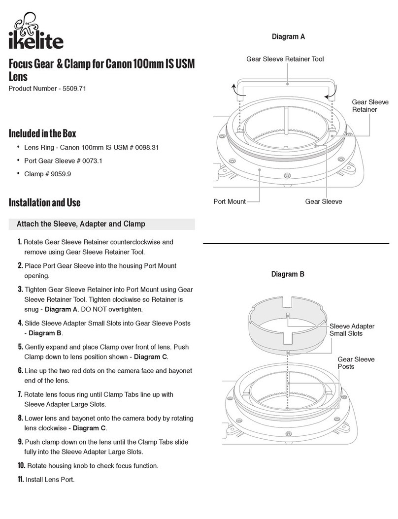
PPrreeppaarriinngg ttoo IInnssttaallll ZZoooomm CCllaammpp && GGeeaarr SSlleeeevvee
Determine the type
of lens being used
on the camera.
Type 1 Lenses have
a lens opening that
is NOT larger in
diameter than the
zoom ring. ((FFiigg.. 11)).
Type 2 Lenses have a lens
opening that IS larger in diameter than the zoom ring. ((FFiigg.. 22)).
ZZoooomm CCllaammppss && GGeeaarr SSlleeeevveess IInncclluuddeedd wwiitthh HHoouussiinngg
There are 2 different
Zoom Clamps and
Gear Sleeves
provided with the
housing. Start with
the suggested Zoom
Clamp and Gear
Sleeve depending
on the Type of
lens being used.
See ((FFiigg.. AA oorr BB))
Figure B-Type 2 Lens
Figure A-Type 1 Lens
lens
opening
zoom
ring
bayonet
mount
Type 1 lens Type 2 lens
(Figure 1) (Figure 2)
Figure G
Normally used with
Type 1 lens (Fig.1)
#9059.8 small diamete clamp:
Fo use with #0073 sleeve
+
#0073 sleeve: Use with
small diamete zoom clamp
#9059.8
Figure A
Normally used with
Type 2 lens (Fig.2)
#5509.28 Package
#9059.9 la ge diamete clamp:
Fo use with #0073.1 sleeve
+
#0073.1 sleeve: Use with
la ge diamete zoom clamp
#9059.9
Figure B
thick ribs thin ribs
wide
grooved
extension
tabs
narrow
grooved
extension
tabs
Figure F
78
IInnssttaalllliinngg tthhee CCaammeerraa
Remove the back from the housing. The mounting tray for the
camera is secured to the housing back. Position the camera and
lens on the tray, and
then secure it with the
mounting bolt which
threads into the
camera’s tripod socket.
Use a flathead
screwdriver
(recommended) or coin
to tighten the mounting
bolt so the camera
bottom is flush against
the tray.
N
NO
OT
TE
E:
: Conversion Circuitry Strobe ID Switch is located on bottom
of camera tray.
SSeettttiinngg tthhee CCoonnvveerrssiioonn CCiirrccuuiittrryy SSttrroobbee IIDD SSwwiittcchh..
On the bottom of the camera tray is a switch for setting the DS
Substrobe ID. Set the switch to the Model of DS Substrobe being
used.
• When using dual
strobes of different
models such as a
DS51 and a DS160,
set the ID switch to
DS51 or the smaller
strobe.
125
160
DS
DS
Set
DS Substrobes
to TTL Mode
50/51
200
80
O‘ring
Mounting Bolt
Camera Tray
CANON
5D
EOS
5
IInnssttaalllliinngg tthhee ZZoooomm CCllaammpp && GGeeaarr SSlleeeevvee OOnn tthhee TTyyppee 11 LLeennsseess
The Zoom Clamp has springs so it can be expanded to fit over
the Zoom Ring of the lens as shown in ((FFiigg.. CC)).
Install the Zoom Clamp with the extension tabs toward the rear
element of the lens. After installing the Zoom Clamp and Gear
Sleeve ((FFiigg.. DD && EE)), install the Lens Port and rotate the Zoom
Ring on the lens. If the Zoom Ring and Gear Sleeve do not mesh
properly, install the rubber strips (supplied) to the inside
diameter of the Zoom Clamp as shown ((FFiigg.. FF)).
Two thicknesses of rubber strips are provided. Start by installing
the thinnest rubber strips. If the Zoom Clamp still is not tight
enough and meshes improperly with the Gear Sleeve, use the
thicker rubber strips. Reinstall the Zoom Clamp, Sleeve. Mesh
Gear Sleeve teeth with Black Housing Drive Gear ((FFiigg.. GG -- PPaaggee
1122)) and then install the Lens Port. After installing the port ((ppaaggeess
1133 && 1144)), rotate the housing Zoom Control Knob to see that the
Gear Sleeve is properly rotating the lens Zoom ring.
9
Type 1 Installation: Figure A
Figure A
Figure C
Type 1 len
mounted
to camera
zoom
ring
10
Type 1 Installation: Figure B
Figure B
Type 1 Installation: Figure C
Figure C
Figure D
Figure E
Align with
Zoom Clamp
grooved tabs
apply
rubber strips
to inside of
clamp
Figure F
TTyyppee 11 LLeennsseess ((ccoonntt..))
Gear Sleeve
ribs
Type 2 Installation: Figure 1
TOP OF HOUSING
IInnssttaalllliinngg tthhee ZZoooomm CCllaammpp && GGeeaarr SSlleeeevvee OOnn TTyyppee 22 LLeennsseess
Due to the larger diameter lens opening on Type 2 lenses, the
Zoom Clamp and Gear Sleeve need to be installed from the rear
(bayonet end) of the lens. Use the housing Lens Release Control
and remove the camera lens from the camera body, after the
camera and lens have been installed in the housing.
Place the Gear Sleeve in the housing opening as shown.
Install the black Zoom Clamp on the Lens Zoom Ring and lower
the lens into the housing opening. Make sure the Zoom Clamp
grooved tabs align with the Gear Sleeve ribs. If necessary,
install rubber strips to expand the Zoom Clamp so it meshes
properly with the Gear Sleeve. Bayonet lens into camera body
and align Gear Sleeve teeth with Black Housing Gear Teeth.
Zoom Clamp
Type 2 len
Lens Zoom Ring
Align
Zoom Clamp
grooved
tabs with
Gear Sleeve
ribs
11
Gear Sleeve
MMaannuuaall FFooccuussiinngg NNoottee::
Ikelite DSLR housings are designed for auto-focus DSLR
cameras and lenses. Manual focusing is not recommended. If
you desire to manually focus a lens, the zoom clamp must be
moved onto the lens Manual Focus Ring and you must use the
housing zoom control knob to manually focus. This will result in
loss of zoom capability.
Lens Manual
Focus Ring
12
IInnttaalllliinngg ZZoooomm CCllaammpp//SSlleeeevvee oonn TTyyppee 22 LLeennsseess ((ccoonntt..))
Before installing the lens port and checking operation, make sure
the teeth on the Gear Sleeve mesh with the teeth on the housing
Drive Gear ((sshhoowwnn bbeellooww))..When the port is installed ((ppaaggeess 1133 &&
1144)), it will lock the Gear Sleeve in place. After installing the port,
rotate the housing Zoom Control Knob to see that the Gear
Sleeve is properly rotating the Lens Zoom ring.
IKELITE
Mesh
Gear Sleeve
teeth with
Black Housing
Drive Gear
Figure G
13
I
In
ns
st
ta
al
ll
li
in
ng
g t
th
he
e P
Po
or
rt
t
There are four port locks on
the front of the housing
((SSeeee FFiigg.. GG -- ppaaggee 1122)). Each
port lock has a Release
Button. Lift the release
button and slide each Port
Lock away from the port
opening. In the unlocked
position, the Release Button
will remain in the up
position as shown.
To prepare the port for installation, remove the port o’ring and
lightly lubricate it. The port seal is a side-to-side seal and
requires the o’ring to be lightly lubricated for easy installation.
Put a small amount of lubricant on your fingers and pull the
o’ring through your fingers to lightly lubricate it. Do not stretch
the o’ring. Check that the lip of the port where the o’ring fits
and the sealing surface on the housing are clean. Place the port,
with o’ring, into the housing port opening. Press down on the
port firmly and evenly until you feel the port slide into place.
Continue to push down on the port and push each port lock
forward until the lock fully engages. It may help to slightly
rotate the port as you push in on the port lock. isually inspect
the port lock and confirm that the Port Lock Release Button is
seated flush against the Port Lock Body. Do not rely on an
audible "click" to indicate that the lock is engaged.
Check around the perimeter of the port seal to see that the
o’ring is properly sealed and not extruded ((SSeeee FFiigg 22 -- ppaaggee 1144))..
Port Lock
Release
Button
Lift Release
Button to
Unlock
Pull Back to
Disengage
P
ort
Locked Position
14
IInnssttaalllliinngg tthhee PPoorrtt ((ccoonntt..))
TToo RReemmoovvee PPoorrtt
To remove the port, lift up on each Release Button and slide the
port lock away from the port.
PPoorrtt SSeeaall IInnssiiddee iieeww
If the port is installed before the
camera is inserted into the housing,
look from the inside of the housing
at the port seal. Check to see that the
o’ring is properly seated as shown in
figure 1 and not extruded as shown
in figure 2.
Fig. 1
Fig. 2
C
Ca
au
ut
ti
io
on
n:
:
After installing the port, turn the Zoom Control knob on the
housing. If the Zoom Control is difficult to turn, the gear sleeve
may be warped. If necessary, reduce or omit any rubber installed
on the Zoom Clamp ((SSeeee FFiigg..FF -- ppgg..1100)).
If the Zoom Clamp is still
warped, use of the #5509.28 package may be required.
(See page 8)
NNOOTTEE:: ((lleennss ppoorrttss))
A lens port must be secured to the housing before entering the
water. Ikelite DSLR housings DO NOT come with a lens port. You
must select the correct port for each lens you will be using
underwater. For complete lens/port information and
compatibility with your Ikelite system, go to wwwwww..iikkeelliittee..ccoomm
15
HHoouussiinngg CCoonnvveerrssiioonn CCiirrccuuiittrryy
This housing has Conversion Circuitry built into the camera tray
((PPaaggee 55)). When used with Ikelite DS Substrobes, the Conversion
Circuitry provides real Canon eTTL flash exposure with over and
under-exposure compensation of two f-stops in half-stop
increments.
The Conversion Circuitry also offers 8 manual power settings in
1/2 stop increments.
The Conversion Circuitry is powered by the Ikelite DS Substrobe
when connected to the housing with the #4103.51 single or
#4103.52 dual sync cord.
See ppaaggee 1199for DS Substrobe compatibility with the Conversion
Circuitry.
16
UUssiinngg tthhee CCoonnvveerrssiioonn CCiirrccuuiittrryy ((SSeett DDSS SSuubbssttrroobbee ttoo TTTTLL mmooddee))
•• MMooddee aanndd CCoommppeennssaattiioonn BBuuttttoonnss
The Conversion Circuitry default is set to TTL. To switch between
TTL and Manual Modes, depress both Mode Buttons at the same
time and keep them depressed until you see the desired Yellow
LED Mode illuminate.
•• TTTTLL MMooddee(indicated when the yellow LED directly below TTL is
illuminated). TTL Mode is the default setting. When the DS
Substrobe is powered ON, the yellow TTL LED will illuminate.
None of the Red LEDs will illuminate. This indicates that no (+)
plus or (-) minus compensation is selected. Depress the Mode
buttons to select +/- compensation. Note that the TTL +/-
compensation values are in the yellow bar with the heading TTL.
•• MMaannuuaall MMooddee(indicated when the yellow LED directly below
the M is illuminated). When the Manual Mode is selected, the
Red LED directly below the F (full power) will illuminate. Note
that the Manual minus (-) compensation values are in the black
bar with the heading M. ((SSeett DDSS SSuubbssttrroobbee ttoo TTTTLL mmooddee.. TThhiiss wwiillll
aallllooww tthhee ssttrroobbee ppoowweerr ttoo bbee vvaarriieedd iinn mmaannuuaall mmooddee ))..
UUssiinngg NNoonn--IIkkeelliittee oorr IIkkeelliittee NNoonn--DDSS SSuubbssttrroobbeess
((SSuubbssttrroobbee 5500,, 110000AA,, 220000,, 440000)) wwiitthh tthhiiss HHoouussiinngg..
The Conversion Circuitry is automatically disabled when used
with a Non-Ikelite or Non-DS Substrobe. These Substrobes can be
used in their manual mode utilizing any power settings provided
on the Substrobe.
17 18
NNOOTTEE:: DDSS SSuubbssttrroobbee UUppddaattee iinnffoorrmmaattiioonn
DDSS5500 SSuubbssttrroobbeess
• DS50 SubStrobes with a Serial Number below 63,850 can not be
updated to operate with the Conversion Circuitry.
• DS50 SubStrobes with a Serial Number between 63,850 and
69,999 operate with the Conversion Circuitry, but require an
update to provide optimum performance.
• DS50 Substrobes with a Serial Number of 70,000 or higher, or
with one of the two following
labels in the battery
compartment provide
optimum performance with
the Conversion Circuitry and
do not need an update.
DDSS112255 SSuubbssttrroobbeess
• DS125 Substrobes with a Serial Number below 2,500 must be
updated to operate correctly with the Conversion Circuitry.
• DS125 Substrobes with a Serial Number between 2,501 and
4,900 will operate with the Conversion Circuitry, but require an
update to provide optimum performance.
• DS125 Substrobes with a Serial Number of 5,000 or higher, or
with one of the two
following labels in the
battery compartment,
provide optimum
performance with the
Conversion Circuitry and do
not need an update.
ikelite
SubstrobeSubstrobe
MOD-NC
TToo UUppddaattee YYoouurr SSuubbssttrroobbee::
Send to the Ikelite address on the back page of this manual or
contact Ikelite for more information.
ikelite
Substrobe
MOD-NC
ikelite
SubstrobeSubstrobe
MOD-NC
ikelite
Substrobe
MOD-NC
serial number
serial number
19 20
RReeccoommmmeennddeedd SSttrroobbee PPaacckkaaggeess
DDSS5511 SSuubbssttrroobbee PPaacckkaaggee ##33994444..5511 includes #4086.61 SA-100 Arm
System with Ikelite TTL sync cord.
AAdddd aa sseeccoonndd SSuubbssttrroobbee DDSS5511:: ##33994444..5522 includes #4086.61 SA-100
Arm System with Ikelite dual TTL sync cord.
DDSS116600 SSuubbssttrroobbee PPaacckkaaggee ##33994444..9900 includes #4086.61 SA-100 Arm
System and 1.5 hour Smart Charger with Ikelite TTL sync cord.
AAdddd aa sseeccoonndd SSuubbssttrroobbee DDSS116600:: ##33994444..9922 includes #4086.61
SA-100 Arm System and Ikelite dual TTL sync cord.
DDSS220000 SSuubbssttrroobbee PPaacckkaaggee ##33994444..6600includes #4085.26 Arm
System and 1.5 hour Smart Charger with Ikelite TTL sync cord.
CCoommpplleettee iinnffoorrmmaattiioonn rreeggaarrddiinngg IIkkeelliittee pprroodduuccttss aanndd ooppttiioonnaall
aacccceessssoorriieess aavvaaiillaabbllee aatt
wwwwww..iikkeelliittee..ccoomm
PPlleeaassee RReeaadd IIff UUssiinngg aann EE--CCoonnttrroolllleerr
TTTTLL ffllaasshh ccoonnttrrooll iiss nnoott aavvaaiillaabbllee wwhheenn uussiinngg aann EE--CCoonnttrroolllleerr,,
aanndd tthheerreeffoorree aann EE CCoonnttrroolllleerr iiss nnoott rreeccoommmmeennddeedd ffoorr uussee
wwiitthh tthhiiss hhoouussiinngg..
NNOOTTEE::The E -Controller cannot be used as a slave. If hard-wired
to the housing, set the E -Controller to Non pre-flash.
ikelite
SUBSTROBE
DS
51
ikelite
Sub trobe DS51
Actual Size
8 cm dia x 12 cm
3.2" dia x 4.7"
SSuubbssttrroobbee DDSS5511
The Substrobe DS51 covers the equivalent of a 28mm lens. The
DS51's intensity and angle of coverage make it equally suited for
macro and general photography.
U
Us
si
in
ng
g I
Ik
ke
el
li
it
te
e D
DS
S D
Di
ig
gi
it
ta
al
l S
St
tr
ro
ob
be
es
s
For the best underwater photographic results, we recommend
adding an external DS-digital strobe connected to the housing with
a #4103.51 TTL Sync Cord and a SA-100 Ball/socket arm ((PPaaggee ##1188)).
Ikelite DS series Substrobes are industry favorites for their warm,
even coverage and lightning fast recycle time. Being farther from
the camera lens, the optional DS Substrobe aids in reducing the
illumination of particles in the water and helps to eliminate
backscatter. When used in conjunction with the E -Controller, the
DS51 Mode switch is set to the TTL setting and the E -Controller
provides ten power settings in half-stop increments.
Test
Off
On
On
w/Lite
TTL
Full
Fuel
Guage
ReadyLight
3
2
1
-2
-3
-4
-1
DS
DS
SUBSTROBE
160
SSuubbssttrroobbee DDSS116600
The Substrobe DS160
covers the equivalent of
an 18mm lens or 100
degrees w/diffuser
installed. It is the ideal
choice when using
accessory wide angle
lenses greater than
28mm. It also features a
1.5 second recycle time
and 225 flashes per full
charge.
Sub trobe DS160
Actual Size
9.6 cm dia x 17.9 cm
3.75" dia x 7"
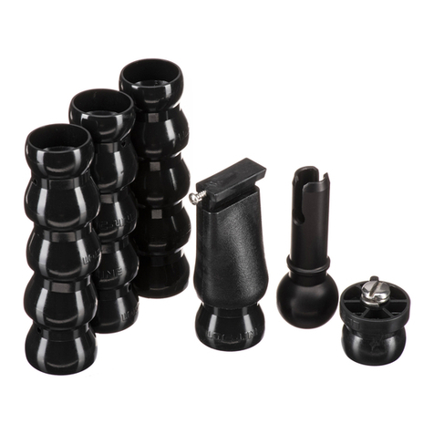
SSAA--110000 BBaallll//SSoocckkeett AArrmm
The SA-100 system #4086.61
with its 1" diameter ball is ideal
underwater. The #9571.3
extended stem mount allows
easy attachment of the E
controller or flashlight mount,
and drops right into the release
handle. The arm system allows
easy strobe placement from
macro close-up to wide angle
without changing aim of the
Sensor. The complete system
removes with a push of the
handle button.
SA-100 Ball/Socket
Arm #4086.61
#9571.3 Extended
Stem Mount (included
with SA-100
Ball/Socket arm)
ikelite
HHoouussiinngg AAcccceessssoorryy MMoouunnttiinngg PPooiinnttss
The top of the SLR-DC housing features a 1/4-20 threaded
mounting point for the attachment of a focus light, video light
or other lightweight accessories.
The bottom of the SLR-DC housing tray also features three
1/4-20 threaded mounting points for attachment of a tripod or
other accessories.

Other manuals for SLR-DC Housing

12

This manual suits for next models

1

Other Ikelite Camera Accessories manuals

Ikelite 6171.05 User manual

Ikelite

Ikelite 6171.05 User manual

Ikelite 6251.03 Wiring diagram

Ikelite

Ikelite 6251.03 Wiring diagram

Ikelite 6146.10 User manual

Ikelite

Ikelite 6146.10 User manual

Ikelite D90 User manual

Ikelite

Ikelite D90 User manual

Ikelite 6146.01 for Canon G1 X User manual

Ikelite

Ikelite 6146.01 for Canon G1 X User manual

Ikelite HDR SR5 Owner's manual

Ikelite

Ikelite HDR SR5 Owner's manual

Ikelite 6973.03 User manual

Ikelite

Ikelite 6973.03 User manual

Ikelite 6243.50 Owner's manual

Ikelite

Ikelite 6243.50 Owner's manual

Ikelite 6870.70 Canon EOS 70D User manual

Ikelite

Ikelite 6870.70 Canon EOS 70D User manual

Ikelite 6182.78 User manual

Ikelite

Ikelite 6182.78 User manual

Ikelite 6282.53 Owner's manual

Ikelite

Ikelite 6282.53 Owner's manual

Ikelite 6060 Owner's manual

Ikelite

Ikelite 6060 Owner's manual

Ikelite Canon 6240.88 Owner's manual

Ikelite

Ikelite Canon 6240.88 Owner's manual

Ikelite Canon 6090 Owner's manual

Ikelite

Ikelite Canon 6090 Owner's manual

Ikelite 5650 User manual

Ikelite

Ikelite 5650 User manual

Ikelite IXUS 980 IS Owner's manual

Ikelite

Ikelite IXUS 980 IS Owner's manual

Ikelite 6242.11 Owner's manual

Ikelite

Ikelite 6242.11 Owner's manual

Ikelite 5509.32 User manual

Ikelite

Ikelite 5509.32 User manual

Ikelite 5510.45 User manual

Ikelite

Ikelite 5510.45 User manual

Ikelite 6130 User manual

Ikelite

Ikelite 6130 User manual

Ikelite SLR-DC User manual

Ikelite

Ikelite SLR-DC User manual

Ikelite SLR-DC Housing User manual

Ikelite

Ikelite SLR-DC Housing User manual

Ikelite 200DLM/A User manual

Ikelite

Ikelite 200DLM/A User manual

Ikelite 6038.82 Owner's manual

Ikelite

Ikelite 6038.82 Owner's manual

Popular Camera Accessories manuals by other brands

CamRanger CamRanger user manual

CamRanger

CamRanger CamRanger user manual

Custom Brackets HDV CAGE KIT Instructions for use

Custom Brackets

Custom Brackets HDV CAGE KIT Instructions for use

Aegis ABL052010P user manual

Aegis

Aegis ABL052010P user manual

Saft SRA Series Installation and operating instructions

Saft

Saft SRA Series Installation and operating instructions

Kodak TIB5200 technical information

Kodak

Kodak TIB5200 technical information

Videotec HEG instruction manual

Videotec

Videotec HEG instruction manual

Pentax Auto Bellows Slide Copier K user manual

Pentax

Pentax Auto Bellows Slide Copier K user manual

Nikon UT-1 user manual

Nikon

Nikon UT-1 user manual

dji RONIN 4D quick start guide

dji

dji RONIN 4D quick start guide

SLIK ABLE 300DX user manual

SLIK

SLIK ABLE 300DX user manual

Rebelcell 36V70 user manual

Rebelcell

Rebelcell 36V70 user manual

Trojan GC2 48V quick start guide

Trojan

Trojan GC2 48V quick start guide

Calumet 7100 Series CK7114 operating instructions

Calumet

Calumet 7100 Series CK7114 operating instructions

Ropox 4Single Series User manual and installation instructions

Ropox

Ropox 4Single Series User manual and installation instructions

Cambo Wide DS Digital Series Main operating instructions

Cambo

Cambo Wide DS Digital Series Main operating instructions

Samsung SHG-120 Specification sheet

Samsung

Samsung SHG-120 Specification sheet

Ryobi BPL-1820 Owner's operating manual

Ryobi

Ryobi BPL-1820 Owner's operating manual

TBB power Energy Hub EH128L user manual

TBB power

TBB power Energy Hub EH128L user manual

manuals.online logo
manuals.online logoBrands
  • About & Mission
  • Contact us
  • Privacy Policy
  • Terms and Conditions

Copyright 2025 Manuals.Online. All Rights Reserved.