6
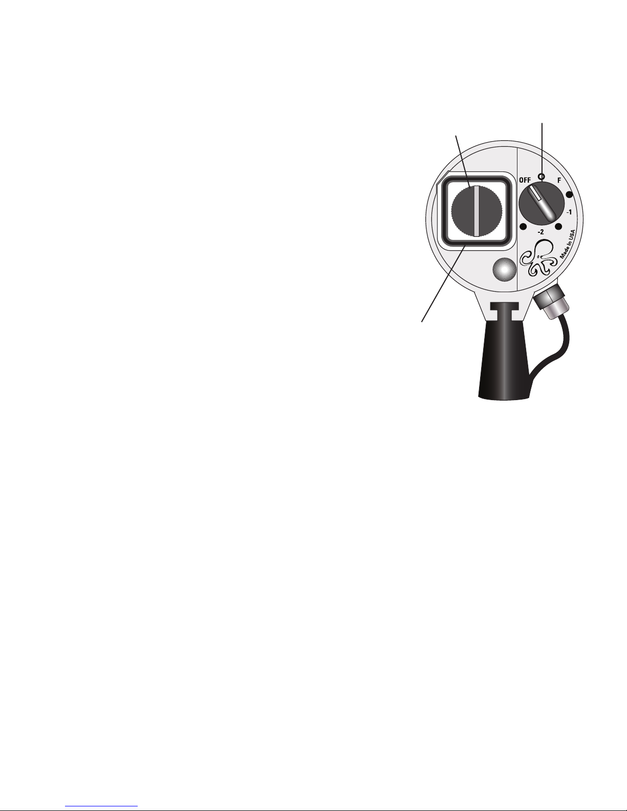
Setting the Auto Exposure Selector Dial
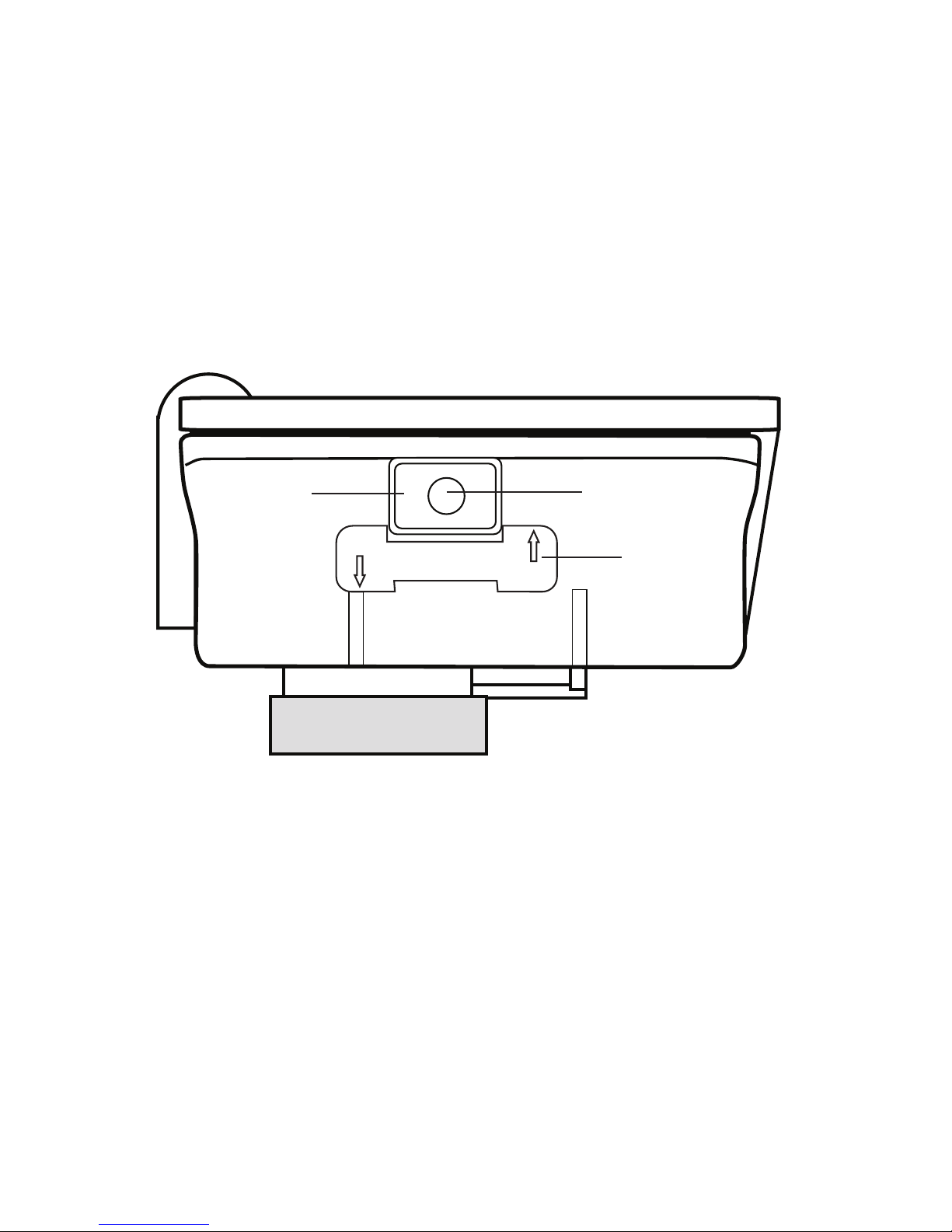
On the side of the Auto Sensor is the Auto
Exposure Selector Dial. Different cameras may
require different exposure values. Once the
correct exposure value is determined for a
particular camera, no further adjustments should
be necessary to obtain acceptable flash
exposures of varying subjects within
normal shooting ranges.
To determine the camera’s optimum Exposure Value we recommend the
following procedure. This procedure can be done above water.
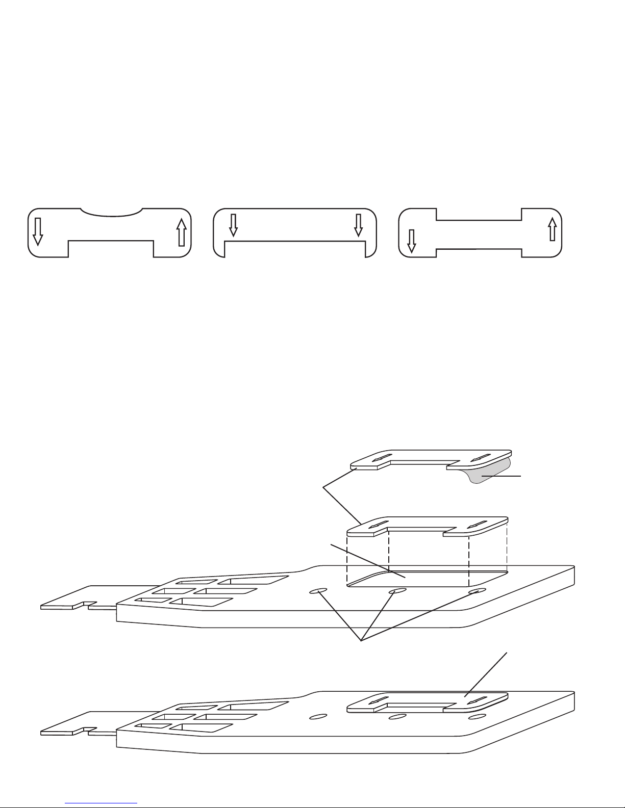
Make sure the camera’s battery is fully charged and the AF35 flash has fresh
batteries. Assemble the AF35 flash and camera housing with the flash
deflector installed on the housing. Make sure the camera’s built-in flash is set
to fire on every shot and is fully charged. Turn the AF35 flash mode dial to
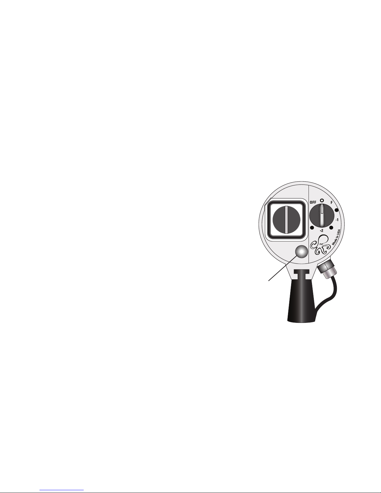
AUTO. Set the Auto Exposure Selector Dial to 5 as shown above. Position the
camera and flash approximately 1m (3 feet) from a colorful subject. Subject
should not be all white or black. Take a picture, review the picture, if the
picture is overexposed (light), turn the Auto Exposure Selector Dial down to 4,
if the picture is underexposed (dark) turn the Auto Exposure Selector Dial up
to 6. Repeat this procedure until the optimum exposure is obtained. Once the
optimum Auto Exposure Value has been determined for that camera, use that
value anytime that camera is used with the AF35 in the Auto Mode. Re eat
this rocedure anytime a different camera is used with the AF35 AutoFlash.
For advanced users, the Auto Exposure Selector Dial can be used for
exposure compensation while remaining in the automatic mode. When the
AF35 Autoflash is set in the Auto Mode the Auto Exposure Selector Dial can
be used to increase or decrease the flash intensity in difficult lighting
conditions.
Ikelite
MADE IN THE USA
2
4
6
8
1
3
5
7
9
10
Auto Exposure
Selector Dial