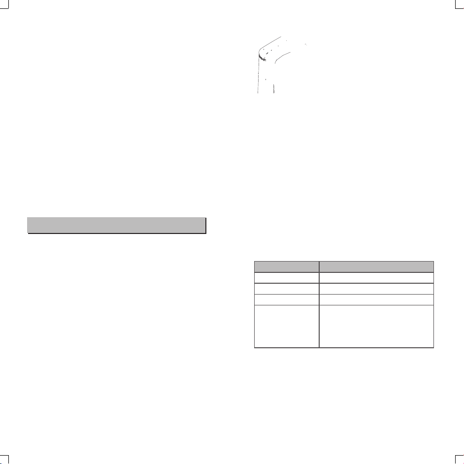
Other Applications
●When not attaching to the camera, the auto focus assist
beam of Li-ion350 N does not light up.
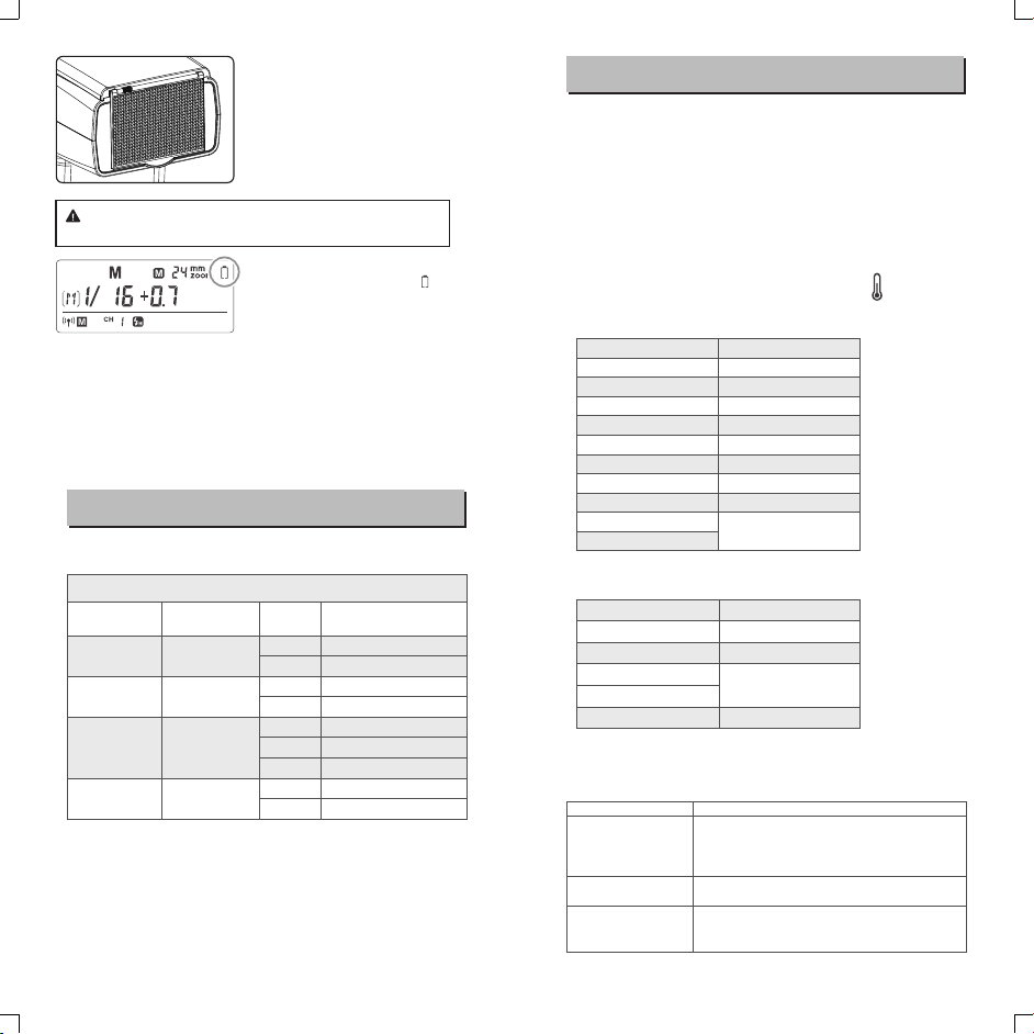
Position
Center
Periphery
Effective Range
0.6~4m
0.6~2.5m
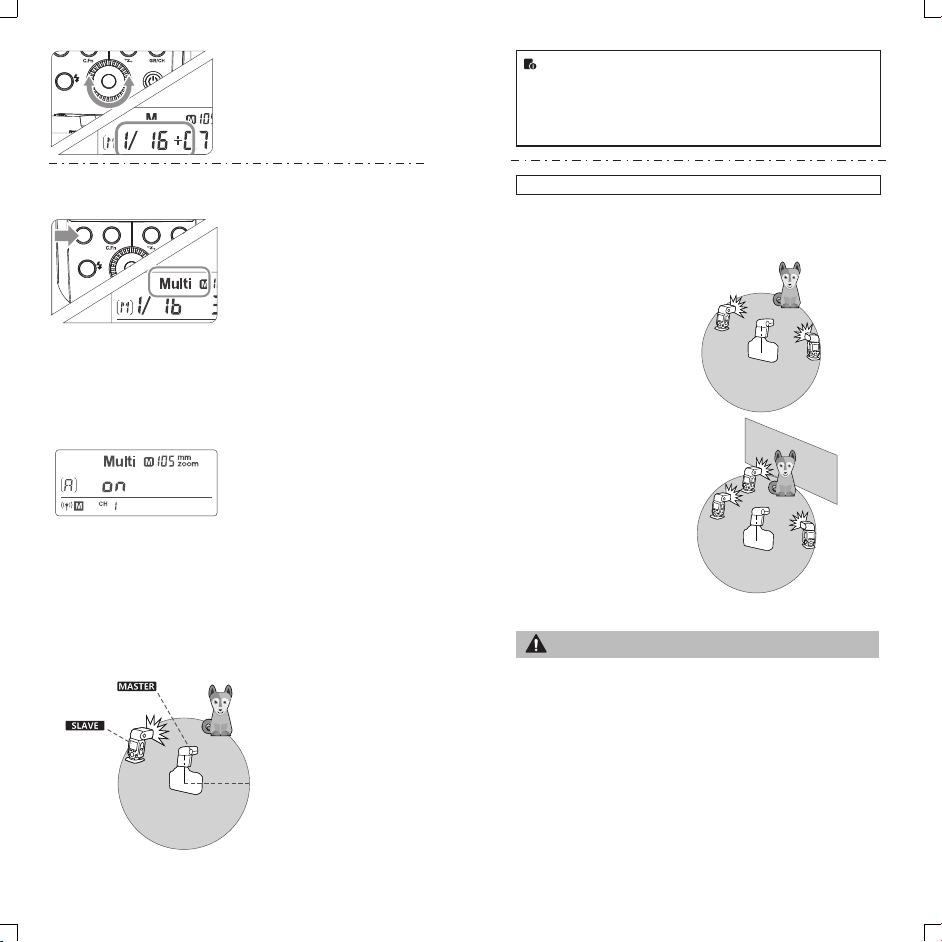
Bounce Flash
By pointing the flash head toward a wall or ceiling, the flash will
bounce off the surface before illuminating the subject. This can
soften shadows behind the subject for a more natural-looking shot.
This is called bounce flash.
To set the bounce direction, hold the flash head and turn it to a
satisfying angle.
● If the wall or ceiling is too far away, the bounced flash might
be too weak and result in underexposure.
● The wall or ceiling should be a plain, white color for high
reflectance. If the bounce surface is not white, a color cast
may appear in the picture.
Creating a Catchlight
With the catchlight panel, you can create a catchlight in the subject’s
eyes to add life to the facial expression.
Point the flash head upward by
190°.
Pull out the wide panel. The
2catchlight panel will come out
at the same time.
Push the wide panel back in.
3
● Push in only the wide panel.
● Follow the same procedures
as for bounce flash.
● Point the flash head straight ahead and then upward by 90°.
The catchlight will not appear if you swing the flash head left
or right.
● For best catchlight effect, stay 1.5m/4.9ft away from the
subject.
ZOOM: Setting the Flash Coverage and Using
the Wide Panel
The flash coverage can be set automatically or manually. It can be
set to match the lens focal length from 24mm to 105mm. Also, with
the built-in wide panel, the flash coverage can be expanded for
14mm wide-angle lenses.
In Manual Zoom mode, press the
<ZOOM> button.
● Turn the Select Dial to change
the flash coverage.
● AUIf < > is displayed, the flash
coverage will be set
automatically.
● If you set the flash coverage manually, make sure it covers
the lens focal length so that the picture will not have a dark
periphery.
● When the low battery indicator is displayed, the ZOOM can
not be adjusted, it will constantly be 24mm.
-19 - - 20 -
3. Whether the distance between the flash trigger and the flash
is too close or not
4.
→Please turn on the “close distance wireless mode” on the flash trigger
(<0.5m):
ST-III series: press the test button and hold on, then turning it on until the
flash ready indicator blinks for 2 times.
ST-IV series: Set the C.Fn-DIST to 0-30m.
Whether the flash trigger and the receiver end equipment are in the low
battery states or not
→Please replace the battery(the flash trigger is recommended to use 1.5V
disposable alkaline battery).
270
-7-90
Auto Focus Assist Beam
Long press the C.Fn to enter C.Fn custom settings and press SET
button: choose “ON” or “OFF” to turn on or off the to the AF-assist
beam function . When turning on the AF-assist beam function: the
red AF-assist lamp will light when it’s hard to focus while
automatically off when getting correct focus.