IKI T600 User manual

IKIT600CHIMNEY
Installationinstructions
09/2017

1

2
IKIT600CHIMNEYINSTALLATIONINSTRUCTIONS
BEFOREINSTALLATION
‐ Checkthatallthepartsyouneedareincludedinthedelivery,usingthelistofpartsasreference(pp.3‐5).
‐ Beforepilingthestonesonthestoveandinstallingthechimney,makesurethestoveishorizontallylevelled
andalignedwiththeholeintheceiling.
‐ Thesafetydistancefromtheoutersurfaceofthefluepipetoinflammablesurfacesinawell‐ventilatedspace
is50mmineachdirection.Donotattachanymaterialstothesurfaceoftheflueunlessitcomeswithaclass
A1firerating.Thesafetydistancefromthetopofthedampertotheceilingis40cm.
‐ Theceilingorwallmayhavemaximum2metreoverflowafterthelastsupport.
‐ Thepartsfortheflueandchimneymustbeusedastheycome,andmaynotbealteredorcut.Thejointsof
thepipesectionsaresecuredwithtighteningstraps.
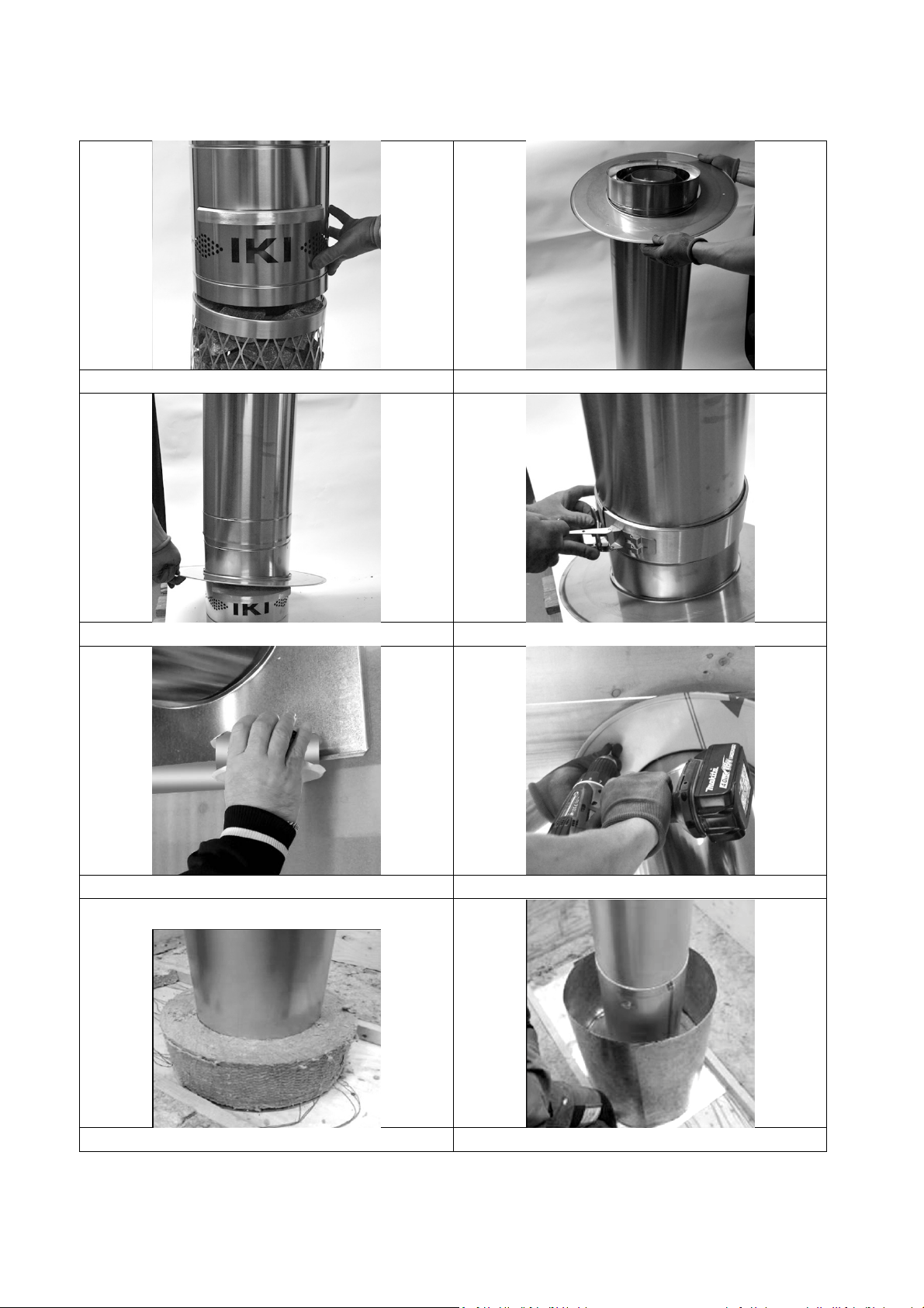
INSTALLATIONINSIDETHESAUNAROOM(PICTURESONPAGES7‐8)
1. Installthedamper(part1)ontopofthestove’smeshframe,fastensecurely.Positionthedamperpanelto
thecorrectdirectioninthesaunaroom(Picture1).
2. Passthe1‐metrefluepipe(part2)throughthecollar(part3)(Picture2).
3. Placethe1‐metrefluepipe(part2)directlyontopofthedamper(part1)(Picture3).Theceilingcollarcan
simplyrestontopofthedamperatthisstageofinstallation.
4. Placethetighteningstrap(part9)tothejointofthedamper(part1)andthe1‐metrefluepipe(part2)and
tightensecurely(Picture4).Attn!Thejointbetweenthedampersectionandthefluepipemaynotneeda
tighteningcollariftheyfitsecurelyastheyare.
5. Usethetapeprovidedtosecurethefumeblockingplate(part4)tothefumeblockintheceilingtightly
(Picture5).Thereneedstobea2‐mmgapbetweenthefumeblockingplateandthepipe,whichisthentaped
shut.
6. Attachthecollartotheceilingwiththescrews(4pieces)providedintheinstallationgearbox(Picture6).
Detachtheprotectiveplasticfromthecollar.
INSTALLATIONINSUBBASE(PICTURESONPAGES7‐8)
7. Placetheceramicfibreinsulation(part5)oncearoundthefluepipe.Minimumheight10cmandminimum
thickness5cm(Picture7).Attn!Thefluepipejointmustnotbelocatedinsidethefibreinsulation.
8. Bendthecylinder(part10)aroundthefibreinsulation(Picture8).Thecylinderneedstobeatleast100mm
higherthantheinsulation(Picture9.)Thestandardcylinderincludedis500mminheight.Ifyourinsulationis
morethan400mminheight,youneedtoincreasethecylinderheightbyusinganother(supplementary)
cylinderandtapethetwocylinderstogether.
9. Attachthesecond1‐metrefluepipesection(part2)onandsecurethejointwithastrap(part6).Secure
bunchedtapeontothestrapandattachtorooftrusseswithscrews(Picture10).
INSTALLATIONONTHEROOF(PICTURESONPAGES7‐8)
10. Attachtheunderlaysheet(part7)totheunderlayleavinga10mmairgapfromthepipesurface(picture11).
Thegapbetweentheedgeoftheraisedunderlayandthechimneypipeisleftopenforventilation.
11. Attachthelast1‐metrefluepipesection(part2)inplaceontheroof.
12. SUPPLEMENTARYEQUIPMENT:Installthesheetmetalset(IKIlightorIKIfull)aroundthechimneyaccording
toseparateinstallationinstructions.Ifyouwanttousedifferentsheetsetswiththeinstallation,theyneedto
beventilated.ItisforbiddentouseproductsnotpartoftheIKIchimneypipesystemwiththischimney
withoutthemanufacturer’swrittenconsent.
13. Placetheraincap(part8)ontoofthechimney(Picture12).

3
IKIT600CHIMNEYPIPELISTOFPARTS:
part1:damper
part2:fluepipe1000mm
part3:ceilingcollar
part4:fumeblockingplate

4
IKIT600CHIMNEYPIPELISTOFPARTS:
part5:ceramicfibreinsulation
part6:supportstrap
part7:underlaysheet
part8:chimneycap

5
IKIT600CHIMNEYPIPELISTOFPARTS:
part9:tighteningstrap
part10:cylinder
Alsoincludedinthedelivery:
2punchedtapesof1000mm
1installationgearboxwithinstructions,screwsandtape

6
7
Picturesoftheinstallation:
Pic1 Pic2
Pic3Pic4
Pic5Pic6
Pic7Pic8

8
Picturesofinstallation:
Pic9 Pic10
Pic11Pic12

9
Chimneyheightonrooftop
InstructionsforuseChimneydetails
Damper
Thedamperpanelneedstobeopenwheneverthereisfire
burninginthehearth,tonotpreventaircooling!
Snowbarrier
Thereneedstobeasnowbarrierontheuppersideofthe
chimneytopreventdamagetochimney.
Sweeping
Thechimneymayonlybesweptwithastainlesssteelor
fibrebrush.
Productplate
Themechanicwillfillintherequiredinformationregarding
theproducttotheplateincludedinthedelivery.Itshould
beplacedsomewhereeasilyvisible.
Ifnecessary,thechimneyneedstobeprotectedfrom
contactwithexternalforces.
IKIT600CHIMNEYPIPE
CE1450‐CPR‐0007
EN1856‐1T600‐N1‐D‐Vm‐L99080‐G(50)
TemperatureclassT600
Safetydistancetoinflammablestructures50mm.
Three‐sheathedair‐ventilatedsteelflueandchimney
system.
Warranty
Themanufacturer,HormexOy,Harkkoraudantie6,
00700Helsinki,issuesa10‐yearwarrantyfor
materialsandproductionerrorsfortheflueand
chimneysystem.Thewarrantydoesnotcoverfor
faultyinstallation.

10

11
Copyright©IKI‐KiuasLtd.
Popular Ventilation Hood manuals by other brands


Accurex
Accurex 470400 Installation, operation and maintenance manual

Electrolux
Electrolux DAV75X Installation and use manual

Novy
Novy Panorama 120 Pro 4 zones installation instructions

Thermador
Thermador HMCB36FS Use & care manual

Electrolux
Electrolux WOL9035CN installation manual

Turbo Incanto
Turbo Incanto T900 Use and maintenance instructions