manuals.online logo
Brands
  1. Home
  2. •
  3. Brands
  4. •
  5. Electrolux
  6. •
  7. Ventilation Hood
  8. •
  9. Electrolux DAV75X Guide

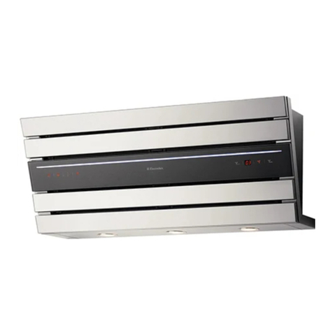
Electrolux DAV75X Guide

Other Electrolux Ventilation Hood manuals

Electrolux Icon E36WC45FSS User manual

Electrolux

Electrolux Icon E36WC45FSS User manual

Electrolux EFC60401OW User manual

Electrolux

Electrolux EFC60401OW User manual

Electrolux WRH605I Series User manual

Electrolux

Electrolux WRH605I Series User manual

Electrolux ERCI931SA User manual

Electrolux

Electrolux ERCI931SA User manual

Electrolux ERC928GA User manual

Electrolux

Electrolux ERC928GA User manual

Electrolux EFD90567OX User manual

Electrolux

Electrolux EFD90567OX User manual

Electrolux IHPL1240WE User manual

Electrolux

Electrolux IHPL1240WE User manual

Electrolux RH36WC55GSA User manual

Electrolux

Electrolux RH36WC55GSA User manual

Electrolux EFP60566OX User manual

Electrolux

Electrolux EFP60566OX User manual

Electrolux LFC316X User manual

Electrolux

Electrolux LFC316X User manual

Electrolux EFC40465OX User manual

Electrolux

Electrolux EFC40465OX User manual

Electrolux EFC90950 User manual

Electrolux

Electrolux EFC90950 User manual

Electrolux ICON RH30WC60GS User manual

Electrolux

Electrolux ICON RH30WC60GS User manual

Electrolux EFC 630 User manual

Electrolux

Electrolux EFC 630 User manual

Electrolux EFC 635 X User manual

Electrolux

Electrolux EFC 635 X User manual

Electrolux EFI 60011 User manual

Electrolux

Electrolux EFI 60011 User manual

Electrolux EFC 90244 User manual

Electrolux

Electrolux EFC 90244 User manual

Electrolux PLHV42P8CC User manual

Electrolux

Electrolux PLHV42P8CC User manual

Electrolux DPB2621S User manual

Electrolux

Electrolux DPB2621S User manual

Electrolux E36WV60EPS User manual

Electrolux

Electrolux E36WV60EPS User manual

Electrolux EFC 9418 User manual

Electrolux

Electrolux EFC 9418 User manual

Electrolux EFB90566BX User manual

Electrolux

Electrolux EFB90566BX User manual

Electrolux CE6010GR User manual

Electrolux

Electrolux CE6010GR User manual

Electrolux LFV719TK User manual

Electrolux

Electrolux LFV719TK User manual

Popular Ventilation Hood manuals by other brands

Gorenje S3 IHGC963S4X manual

Gorenje

Gorenje S3 IHGC963S4X manual

KOBE ISX2136SQB-1 Installation instructions and operation manual

KOBE

KOBE ISX2136SQB-1 Installation instructions and operation manual

U.S. Products ADVANTAGE-100H Information & operating instructions

U.S. Products

U.S. Products ADVANTAGE-100H Information & operating instructions

Kuppersberg DUDL 4 LX Technical Passport

Kuppersberg

Kuppersberg DUDL 4 LX Technical Passport

Framtid HW280 manual

Framtid

Framtid HW280 manual

Thermador HGEW 36 FS installation manual

Thermador

Thermador HGEW 36 FS installation manual

AEG X69453MVO UK user manual

AEG

AEG X69453MVO UK user manual

Broan B5836SS manual

Broan

Broan B5836SS manual

Heinner HDCH-6060RGBK quick start guide

Heinner

Heinner HDCH-6060RGBK quick start guide

Baumatic AS35SS instruction manual

Baumatic

Baumatic AS35SS instruction manual

Franke FTF 604 XS V2 Instructions for use and installation

Franke

Franke FTF 604 XS V2 Instructions for use and installation

Best UCB3I30SBW installation instructions

Best

Best UCB3I30SBW installation instructions

Gram EFU 503-90 X instruction manual

Gram

Gram EFU 503-90 X instruction manual

CIARRA CBCS6803 Installation and user manual

CIARRA

CIARRA CBCS6803 Installation and user manual

sauter SHG501 Instructions for installation and use

sauter

sauter SHG501 Instructions for installation and use

Franke 392-17 User instructions

Franke

Franke 392-17 User instructions

FALMEC Polar Black 35 Instruction booklet

FALMEC

FALMEC Polar Black 35 Instruction booklet

AEG 740 D Operating and installation instructions

AEG

AEG 740 D Operating and installation instructions

manuals.online logo
manuals.online logoBrands
  • About & Mission
  • Contact us
  • Privacy Policy
  • Terms and Conditions

Copyright 2025 Manuals.Online. All Rights Reserved.

MANUALE DI INSTALLAZIONE, USO E MANUTENZIONE
INSTALLATION, USE AND MAINTENANCE HANDBOOK
MANUEL D’INSTRUCTIONS POUR L’INSTALLATION, L’EMPLOI ET L’ENTRETIEN
HANDBUCH FÜR INSTALLATION, BEDIENUNG UND WARTUNG
INSTRUCTIES VOOR MONTAGE, GEBRUIK EN ONDERHOUD
MANUAL DE INSTRUCCIONES, USO Y MANTENIMIENTO
MANUAL DE INSTRUÇÕES, UTILIZAÇÃO E MANUTENÇÃO
2
C ntenuti - C ntenents - S mmaire - Inhalt - Inh ud - C ntenid - C nteúd
Generalità .................................................. 4
General Information .................................. 10
Generalites ................................................ 16
Allgemeines ............................................... 22
Algemeen ................................................... 29
Generalidades .......................................... 36
Informações Gerais .................................. 43
Componenti .............................................. 4
Components ............................................. 10
Composants .............................................. 16
Bauelemente .............................................. 22
Onderdelen ................................................ 29
Componentes ........................................... 36
Componentes ............................................ 43
Avvertenze per la Sicurezza ...................... 4
Safety Warnings ........................................ 10
Conseils concernant la Securite .............. 16
Sic er eits inweise ................................. 22
Veilig eidsmaatregelen ............................ 29
Advertencias de seguridad ...................... 36
Precauções de segurança ........................ 43
Installazione .............................................. 5
Installation ................................................. 11
Installation ................................................. 17
Montage des Gerätes ................................ 23
Montage ..................................................... 30
Instalacion ................................................. 37
Instalação .................................................. 44
• M ntaggi del tralicci telesc pic superi re
• Fitting f upper telesc pic frame
• M ntage du supp rt télesc pique supérieur
• M ntage des Telesk pgerüsts
• M ntage van het telesc pische
bevestigingsgeraamte
• M ntaje del armazón telescópic superi r
• M ntagem da estrutura telescópica superi r
• M ntaggi del tralicci telesc pic inferi re
• Fitting the l wer telesc pic frame
• M ntage du supp rt télésc pique inférieur
• M ntage des unteren Gerüsts
• M ntage van het nderste telesc pische
bevestigingsgeraamte
• M ntaje del armazón telescópic inferi r
• M ntagem da estrutura telescópica inferi r
• C nnessi ne aspirante filtrante
• Setting the h d f r evecuati n r recirculati n
• Racc rdement versi n évacuati n u recyclage
• Anschluß für Abluft- der Umluftbetrieb
• Afzuig- f recirculatie afstelling
• C nexión aspirante filtrante
• Ligaçã para a versã aspirante u filtrante
• Allacciament elettric alla rete di alimentazi ne
• Electrical c nnecti n
• Branchement électrique au réseau d’alimentati n
• Elektrischer Netzanschluß
• Aansluiting p het elektriciteitsnet
• C nexión eléctrica c n la red de alimentación
• Ligaçã eléctrica à rede de alimentaçã
• M ntaggi del camin
• Fitting the chimney
• Branchement de la cheminée
• M ntage des Kamins
• M ntage van de sch uw
• M ntaje de l chimenea
• M ntagem da chaminé
• M ntaggi del c rp cappa
• Fitting the can py
• M ntage du c rps de h tte
• M ntage des Haubenkörpers
• M ntage van de afzuigkap
• M ntaje de la campana
• M ntagem d c rp d exaust r
• C nnessi ne elettrica
• Electrical c nnecti ns
• Branchement électrique
• Elektrischer Anschluß der Bedienungselemente
• Elektrische aansluiting
• C nexión eléctrica
• Ligaçã eléctrica
3
C ntenuti - C ntenents - S mmaire - Inhalt - Inh ud - C ntenid - C nteúd
Avvertenze per la Sicurezza .................... 8
Safety Warnings ....................................... 14
Conseils concernant la Securite ............. 20
Sic er eits inweise ................................ 27
Veilig eidsmaatregelen ........................... 34
Advertencias de Seguridad ..................... 41
Precauções de segurança ....................... 48
Uso ............................................................ 8
Operation .................................................. 14
Utilisation ................................................. 20
Areitsweise der dunst Haube .................. 27
Gebruik ..................................................... 34
Uso ............................................................ 41
Utilização .................................................. 48
Manutenzione ........................................... 8
Maintenance ............................................. 14
Entretien ................................................... 20
Wartung und Pflege ................................. 27
Onder oud ............................................... 34
Mantenimiento ......................................... 41
Manutenção .............................................. 48
• Filtri antigrass metallici
• Metal grease filters
• Filtres à graisses métalliques
• Metall-Fettfilter
• Metalen vetfilters
• Filtr antigrasa metálic s
• Filtr s metálic s antig rdura
• Filtri al carb ne attiv
• Charc al filters
• Filtres à charb n actif
• Aktiv-K hlefilter
• Aktief k lsfilter
• Filtr de carbón activ
• Filtr s de carvã activ
• Illuminazi ne
• Lighting
• Eclairage
• Beleuchtung
• Verlichting
• Iluminación
• Iluminaçã
• Pulizia
• Cleaning
• Nett yage
• Pflege
• Reiniging
• Limpieza
• Limpeza
10
1 - GENERAL INFORMATION
This h d is designed f r installati n ver a c king appliance fitted int a
peninsular r island kitchen cabinet. The h d can be fixed t the ceiling r t a
w den buttress (fig. 2). The h d is supplied c mplete with a substantial ceiling
fixing system which is fully adjustable in height t suit m st installati n
requirements. This can py h d is designed t be used either in the extracti n
m de (ducted t the utside) r in the recirculati n m de (internal recycling).
Before commencing t e installation, consideration s ould be given to t e
difficulties to be found during installation and to t e bulky weig t of t e
ood. T e installation work must be undertaken by a qualified and
competent person in conformity to t e rules concerning t e evacuation of
contaminated air. T e manufacturer disclaims all liability for any damage or
injury caused as a result of not following t e instructions for installation
contained in t e following text.
2 - COMPONENTS
The c ker h d is made up f the f ll wing c mp nents (fig. 1):
2.1 - n . 1 can py item “C”, including c ntr ls, w rkt p illuminati n and fan unit
2.2 - n . 1 telesc pic frame c nsisting f:
n . 1 upper frame “TS”
n . 1 l wer frame “TI”
2.3 - n . 1 telesc pic chimney stack f rmed by:
n . 1 upper secti n item “S”
n . 1 l wer secti n item “I”
n . 1 bag f screws and access ries
n . 1 recirculati n venting grille item “G”
2.4 - n . 1 recirculati n spig t item “F”
2.5 - n . 1 reducti n flange Ø 150-200 item “R”
3 - SAFETY WARNINGS
3.1 - T e cooker ood ducting must not be connected to a flue w ic is used for
ex austing fumes from appliances supplied wit energy ot er t an electric suc as
a central eating flue or water eating flue.
3.2 - Ensure t at t e mains voltage corresponds wit t e voltage on t e rating plate
inside t e ood.
3.3 - Connect t e cooker ood to t e mains via a double pole switc w ic as 3 mm
clearance between t e contacts.
3.4 - T e appliance must be eart ed.
Part 1 - INSTALLATION INSTRUCTIONS
11
3.5 - T e ood must be positioned at least 65 cm above a cooking appliance.
3.6 - Never do flambé cooking under t is cooker ood.
3.7 - Never leave frying pans unattended during use as over eated fats and oils may
catc fire.
3.8 - Before carring out any kind of maintenance or cleaning, disconnect t e ood from
t e mains supply.
3.9 - If t e room w ere t e cooker ood is to be used contains a fuel burning appliance
suc as a central eating boiler, ensure t at t ere is an adequate supply of air into
t e room. W en t e cooker ood is used in conjunction wit ot er appliances
supplied wit energy ot er t an electric, t e negative pressure in t e room must not
exceed 0,04 mbar to prevent fumes being drawn back into t e room by t e cooker
ood.
4 - Installation
T install the h d pr ceed by fitting the c mp nents in the f ll wing rder:
4.1 - Fitting f upper telesc pic frame “TS”
4.2 - Fitting f l wer telesc pic frame “TI”
4.3 - Setting the h d f r recirculati n r evacuati n
4.4 - C nnecti n t the mains supply
4.5 - Fitting the chimney
4.6 - Fitting the can py
4.7 - Electrical c nnecti n f c ntr ls and functi nal test
4.1 - Fitting of upper telescopic frame “TS”
The frame is suitable f r fixing t the ceiling as illustrated in (2A) r t a w den
buttress (2B) f adequate thickness and well secured t the ceiling r ther
carrying structure. Remember that the recycled air can be directed in f ur different
directi ns: such ch ice must be made when securing the upper frame (see p int
“d”).
a) Separate the l wer frame “TI” (6C) fr m the upper part “6A” by l sening the f ur
retaining screws “6B” with the s cket head screw wrench pr vided “6D”.
b) Rem ve the screws “3A” and pull ut the upper pipe “S”(3B) f the telesc pic
chimney.
c) Using a plumb line r similar t l, mark the centre n the ceiling r buttress fr m
the centre f the c king appliance.
d) (fig. 5) Use the drilling template “5A” pr vided t mark the centre n the ceiling r
w den buttress and align ne f the tw axes (A r B) f the template parallel
with the l ng side f the h b “5C” bearing in mind in which directi n y u want the
filtered air t exit. Vent directi n 1 r 2, as indicated n the template, is determined
during the subsequent fitting phase f the l wer frame (paragr. 4.2). Mark the
p siti n f the 4 h les n the template, plus the p wer cable h le.
e) P siti n “5E” indicates the useful area t pass the mains cable.
Part 1 - INSTALLATION INSTRUCTIONS
12
f) Drill the h les as f ll ws:
- ceiling: 4 h les Ø 10 mm f r securing the upper frame
1 h le Ø 10 mm t pass the mains cable
- buttress: 4 h les Ø 8 mm f r securing the upper frame
1 h le Ø 10 mm t pass the mains cable.
g) For extraction mode wit ceiling vent only
Use the template pr vided t mark the ø 125 mm h le n the ceiling f r ducting
when the range h d is t be installed in the extracti n m de.
h) Fitting t e ood to t e ceiling
Attention: Due t the many differing types f ceiling c nstructi n, the ch ice f
fixings is left t the discreti n f the installer. It is necessary t emphasise that the
fitting has t be absolutely accurate because f the weig t f the c ker h d
and bacause f the flexing caused by accidental lateral stresses n the
appliance. Only the f ll wing types f ceiling are suitable f r installing the island
c ker h d:
1 - S lid c ncrete ceiling: use d wels f r c ncrete (not supplied).
2 - S lid w den buttress ceiling: use Ø 10 mm w d screws with a minimum
length f 120 mm (not supplied).
3 - Cavity ceiling with inner empty space, having a thickness f ab ut 20 mm:
use, in t is case, the f ur d wels and screws supplied. Once fixed, make sure
that the basis is abs lutely stable even when the metal frame is subjected t
lateral stresses.
4 - If the ceiling is n t str ng en ugh in the area where the h d is t be fixed,
the installer must strengthen the area adequately s that it can withstand the
weight f the h d.
i) W en fitting t e ood to a wooden buttress: secure the frame t the base f
the buttress using the f ur M6 x 80 mm nuts and b lts pr vided.
4.2 - Fitting the lower telescopic frame “TI”
a) Turn the l wer telesc pic frame “TI” (6C) acc rding t the ch sen directi n f
filtered air vent: “6U” r r tating the frame “6C” in the pp site directi n.
b) C nnect the l wer frame “TI” (6C) t the upper frame “TS” (6A) and secure by
tightening the 4 screws “6B” using the s cket head screw wrench pr vided “6D”,
adjusting the height fr m the h b and bearing in mind that the can py item t be
fitted subsequently is 7 cm high. In any event, in this p siti n, the l wer part f the
frame must n t be p siti ned at less than 72 cm fr m the underlying h b.
4.3 - Setting the hood for evacuation or recirculation
1 - Setting f r evacuati n:
a) Apply the reducing spig t “7B” t the upper part f the extracti n unit “7D”.
b) C nnect spig t “7B” t the external ducting by means f rigid r flexible duct
“7G” (n t pr vided) t be fixed using clamps “7F” pr vided.
c) Rem ve any charc al filter in the l wer part f the can py (see paragr. 3.2 - part
tw ).
Part 1 - INSTALLATION INSTRUCTIONS
13
2 - Setting f r recirculati n:
a) Apply the reducing spig t “7B” t the upper part f the extracti n unit “7D”.
b) Fit the recycling spig t “7A” t the reducing spig t “7B”, directing it in the p siti n
ch sen f r air evacuati n.
c) Fit the charc al filter inside the can py (see paragr. 3.2 - part tw ) after p wer
c nnecti ns have been d ne (paragr. 4.7).
4.4 - Electrical connection
a) Always carefully f ll w all instructi ns in paragr. 3 c ncerning safety.
b) C nnecti n t mains supply must be d ne by passing the p wer cable thr ugh the
centre h le f the frame.
c) C nnect the mains cable t the mains supply.
4.5 - Fitting the chimney
a) Insert the upper pipe “S” (4B) f the telesc pic chimney and secure with the tw
screws “3A”.
b) Insert the l wer pipe “I” (4C) f the telesc pic chimney, p siti ning it s that
pening “4D”, in the event f evacuati n fitting, is aligned with the recircualti n
spig t “7A”. N te: D n t fit the small directi nal grille “G”. This perati n must be
d ne after installati n f the can py “C”. Supp rt pipe “4C” with ne hand t all w
subsequent fitting f the can py item.
4.6 - Fitting the canopy
a) Rem ve the three grease filters “8D” by applying pressure t the handles “8E”.
b) If fitted, rem ve the tw charc al filters “8C”.
c) P siti n the can py item “8A” in line with the h les f l wer frame “I” and secure
with 4 screws “8B”. N te: N further perati n must be carried ut with ut having
tightened the 4 screws “8C”. During this perati n, until at least ne screw “8C”
has been tightened, slightly supp rt the can py item t av id accidental
m vement.
d) Fit the directi nal grille “4E” in sl t “4D”.
4.7 - Electrical connections
a) Rem ve c ver “9B” by rem ving screw “9A”.
b) Rem ve c nnect r “9D” and c nnect it t “9E” fr m the m t r assembly.
c) Refit the c ver “9B” paying attenti n that the c nnect r cable is c rrectly
p siti ned in sl t “9C”.
d) Once all the c nnecti ns have been d ne, check c rrect perati n f:
- LIGHTS
- MOTOR START
- SPEED CHANGE
Part 1 - INSTALLATION INSTRUCTIONS
14
1 - SAFETY WARNINGS
It is most important t at all t e warnings s own in paragrap 3 of t e Installation
Instructions are strictly observed. Moreover, pay special attention to t e following
warnings during t e use and maintenance of t e cooker ood:
1.1 - T e grease filters and t e c arcoal filter s ould be cleaned or replaced as
recommended by t e manufacturer or more frequently if t e ood is used
consistently over 4 ours per day.
1.2- W en using a gas ob in connection wit t e cooker ood never leave t e burners
of t e ob uncovered w ile t e ood is in use or w en t e pans ave been
removed. Switc off t e gas before removing t e pan, or for just s ort periods and
never leave t e ob unattended.
1.3 - Always ensure t at t e flame is kept at t e correct intensity to prevent t e flame
from licking round from t e bottom of t e pan: t is will save energy and will avoid
a dangerous concentration of eat.
1.4 - Always ensure t at t e appliance is used in accordance wit t e manufacturer’s
instructions for t e removal of contaminated air and odours during cooking.
2 - OPERATION
C ntr l Panel (fig. 10)
C ntr ls are as f ll ws:
SWITCH “L” = C ntr ls the w rkt p illuminati n
SWITCH “M” = C ntr ls the p wer t the m t r
SWITCH “V” = C ntr ls the fan speed:
P siti n 1 = l w speed, sh uld be selected when simmering r using nly ne
pan; the n ise level is kept t the minimum.
P siti n 2 = medium speed, sh uld be selected f r n rmal c king. This speed
ffers the best rati between air capacity and n ise level.
P siti n 3 = t p speed, sh uld be selected when frying r c king f d with
str ng d urs, even f r a l ng peri d.
3 - MAINTENANCE
Regular maintenance and cleaning will ensure g d perf rmance and reliability,
while extending the w rking life f the h d. Special attenti n sh uld be paid t
the grease filters and t the charc al filters when the h d is used in the
recirculati n m de.
3.1 - Metal grease filters
1 - Cleaning
These sh uld be washed with n rmal h me detergents at least every 2 m nths;
their c mpact dimensi ns als all ws washing in a dishwasher.
Part 2 - USE AND MAINTENANCE INSTRUCTIONS
15
Part 2 - USE AND MAINTENANCE INSTRUCTIONS
2 - Rem ving the filters:
a) Rem ve the filters “8D” ( ne at a time) by means f handles “8E”, pushing these
t wards the rear part f the h d and at the same time pulling d wnwards.
b) Refit the filters, keeping the handle in a visible and fr nt p siti n.
IMPORTANT: The indicated maintenance schedule must be f ll wed t prevent
the p ssibility f fire if the filters are saturated with grease.
3.2 - Charcoal filters
1 - Operati n
Charc al filters are able t abs rb smells up t saturati n. They are n t washable,
cann t be regenerated and must theref re be replaced every 4 m nths r m re
frequently in the event f extensive use.
2 - Replacement:
a) Rem ve the grease filters “8D” ( ne at a time) by means f handles “8E”,
pushing these t wards the rear part f the h d and at the same time pulling
d wnwards.
b) Rem ve the tw filters “11A” by means f levers “11B”.
IMPORTANT: The indicated maintenance schedule must be f ll wed t prevent
the p ssibility f fire if the filter is saturated with grease.
3.3 - Lighting
This c nsists f f ur 20 W hal gen lamps. T replace, pr ceed as f ll ws (fig. 12):
a) Rem ve the tw screws “12B”.
b) Raise the retaining ring “12A”.
c) Rem ve the lamp “12C” and replace with an ther having the same
characteristics.
3.4 - Cleaning
When cleaning the h d:
- Never use a wet cl th r sp nge, r running water.
- Never use thinners r pr ducts c ntaining alc h l, as they might damage the
paintw rk.
- Never use abrasive cleaning materials, in particular when cleaning stainless steel
surfaces.
It is recommended to use a damp clot and mild liquid ouse old cleaner.
50