ILLKO FITESTpro User manual

V 1.6-EN
FITESTpro
USER’S
MANUAL

FITESTpro
-1-
1. INTRODUCTION............................................................................. 2
1.1. Safety.......................................................................................... 2
1.2. General description of the instrument.......................................... 3
1.3. Standards applied ....................................................................... 3
1.4. Ecology ....................................................................................... 4
2. DESCRIPTION OF THE INSTRUMENT ......................................... 5
2.1. Instrument’s case ........................................................................ 5
2.2. Control panel and LED display ................................................. 6
2.3. Included in the set ....................................................................... 7
2.4. ptional accessories ................................................................... 7
2.5. Putting the instrument into operation ........................................... 7
3. MEASUREMENTS.......................................................................... 8
3.1. Turning the instrument on and off, standby, auto power off ......... 8
3.2. Notes and principles applicable to all measurements .................. 8
3.3. Parameters that can be set ....................................................... 11
3.4. Measurement of RCD parameters............................................. 12
3.4.1. Contact voltage Uc............................................................................ 12
3.4.2. Trip-out time TIME ............................................................................ 14
3.4.3. Trip-out current I............................................................................ 15
3.5. ther functions of the instrument............................................... 16
3.6. RESET of the instrument........................................................... 17
4. MAINTENANCE ........................................................................... 18
4.1. Batteries and fuse replacement................................................. 18
4.1.1. Inserting and replacing the atteries / accumulators......................... 18
4.1.2. Charging of accumulators ................................................................. 19
4.1.3. Replacing the fuse ............................................................................ 20
4.2. Cleaning.................................................................................... 20
4.3. Calibration ................................................................................. 20
4.4. Service ...................................................................................... 20
5. TECHNICAL SPECIFICATION ..................................................... 21
5.1. Functions................................................................................... 21
5.2. General data ............................................................................. 23

FITESTpro
-2-
1. INTRODUCTION
1.1. Safety
Read this User’s Manual carefully and completely and follow all
instructions contained therein. Otherwise using of the instrument
may be dangerous for operator, for installation under test under
test or for the instrument!
Explanation of the sym ols on the instruments:
Protection class (dou le insulation)
Danger of electric shock
Warning concerning a point of danger!
Read User’s Manual and o serve all precautions!
The instrument meets the requirements of relevant European standards
If there is reason to elieve that safe operation has ecome impossi le,
put the instrument out of operation and secure it against any unintended
operation. Safe operation must e presumed to e no longer possi le, if:
•The instrument does not operate properly any longer. In this case, we
recommend RESET as descri ed in the Chapter 3.6.
•The instrument, ca les, connectors, plugs or accessories exhi its visi le
damages.
•The instrument was stored under unfavoura le conditions for a long period.
•The instrument was exposed to extraordinary stress caused y transport.
•The atteries / fuse compartment cover is not properly fastened y oth
screws.
O serve the following safety precautions:
•Make sure that the instrument, measuring ca les and all other accessories
are in flawless condition, e.g. no damaged insulation, no roken ca les or
plugs etc.
•Do not touch conductive parts of test tips, crocodiles, test ca les etc., even if
only one test tip, crocodile, test ca le etc. is connected to installation.
DANGER OF ELECTRIC SHOCK!
•Only a trained, skilled person, who is familiar with hazardous voltage
operations, can handle the instrument.
•It is necessary to respect all safety regulations applica le to particular
measurement.
•Use only standard or optional accessories supplied y the instrument y your
distri utor.
•Do not press any key (unless otherwise stated in this manual) when
connecting the instrument to the measured installation.

FITESTpro
-3-
•The instrument can e used only under conditions that are specified in
Technical Specification, see Chapter 5.
•Do not expose the instrument to aggressive gases, vapours, liquids and dust.
•If you have transferred the unit from cold to hot environment, it can cause the
condensation. We recommend a short acclimatization.
•If the device will e out of operation for a longer time, it is recommended to
remove the atteries. This prevents the possi ility of leakage into the device.
Leakage can cause serious damage or to destroy the instrument.
•RCD under test can trip-out even if it should not trip-out during particular
measurement(s). This may e due, inter alia, faulty RCD or ecause of a
leakage current flow via RCD under test which adds up the differential current
generated y the instrument. This may result in interruption of operation of
various equipment(s) and cause damage (e.g. loss of data in computers) and
/ or threats, including threats to life or health (e.g. health facilities). Therefore,
we strongly recommend that measurements are carried out in agreement with
a person who is responsi le for the operation of the o ject under test and who
implement measures to prevent any damage. The simplest such measure (if it
is possi le) is to turn off such equipment(s).
•The instrument contains two fairly strong magnets. Do not leave them near
the equipment and items that could e damaged y the magnetic field - such
as watches, credit cards with magnetic strips, etc.
•Images in this manual are illustrative and may vary slightly from the actual
state.
1.2. Gene al desc iption of the inst ument
The FITESTpro is a compact instrument with patent-protected storage system of
the test tips in the transport position – sharp tips are safely hidden.
High contrast right multicolour graphic OLED display ensures excellent
legi ility. When measured under low light conditions it is possi le to illuminate
the measured o ject y a right white LED light positioned on the front side of
the housing.
The FITESTpro can measure:
- RCD trip-out time
- RCD trip-out current
- RCD contact voltage
- Loop resistance (no-trip of RCD)
- AC voltage
- Phase (live) conductor test
1.3. Standa ds applied
Measurements: EMC: Safety:
EN 61557-1 EN 55022, class B EN 61010-1
EN 61557-6 EN 61326-1 EN 61010-2-031
EN 61000-4-2,3,4,5,6

FITESTpro
-4-
1.4. Ecology
Shipping case
It is made of card oard and is recycla le. Please hand it to a collection point of
secondary raw materials in accordance with local regulations.
Batteries
Please dispose of used atteries in the designated locations in accordance with
local regulations.
The instrument
This sym ol on the product, packaging or the accompanying
documentation indicates that the product should not e dispose of in
municipal waste.
Please dispose of it in accordance with local regulations.

FITESTpro
-5-
2. DESCRIPTION OF THE INSTRUMENT
2.1. Inst ument’s case
Fig. 2.1. Top side
When not in use, the instrument’s ody and the mova le test tip can slide one
into another in such a way that they form a compact unit, while the sharp end of
the measuring tips are safely hidden. Against accidental ejection are oth parts
secured y non-contact magnetic latch.
•Use original
accessories
only!
•Max allowed
voltage etween
test tip and
ground is 300V!
•Max allowed
voltage etween
test tips is 300V!
instrument’s
case
control panel
OLED display
test tip on instrument’s case
socket
for accumulators’
charger
terminal for connecting of
mova le test tip
sliding
protective
cover
mova le
test tip
LED

FITESTpro
-6-
Fig. 2.2. Detail of bottom side
2.2. Cont ol panel and OLED display
Graphical OLED display
ST RT key starts measurement, if test tips
are connected to voltage.
If there is no voltage on test tips,
it controls white LED (see Fig. 2.1).
The key switches the instrument
on and off, too.
FUNC key selects measured
function.
I∆Nkey selects nominal
differential current.
TYPE key selects RCD
type and differential
current shape.
xI∆Nkey selects multiplier of nominal
differential current or limit contact voltage.
Fig. 2.3. Control panel and OLED display
screws securing the atteries /
fuse compartment cover
the atteries / fuse compartment
cover and information la el

FITESTpro
-7-
attery indicator overheating indicator
measured function
nominal differential
current and its multiplier
Fig. 2.4 Example of displayed information
The information displayed may vary according to the function, the voltage which
is applied on the test tips, etc.
2.3. Included in the set
FITESTpro
Twisted test lead with measuring tip
Pouch
User’s Manual
Cali ration Certificate
Card oard shipping case
2.4. Optional accesso ies
P 5050 – adapter for charging accumulators
P 5060 – set of 4 NiMH AAA accumulators
P 2011 – test lead, lack, 2 m
P 3011 – test tip, lack
P 4011 – crocodile clip, lack
Note: optional accessories P 2011 + P 3011, respectively P 2011 + P 4011 can
e connected instead of twisted test lead with measuring tip.
2.5. Putting the inst ument into ope ation
Putting the instrument into operation consists of inserting the atteries or
accumulators - the procedure is descri ed in the Chapter 4.1. of this manual.
RCD type,
diff. current shape
secondary measured
value
main measured value

FITESTpro
-8-
3. MEASUREMENTS
3.1. Tu ning the inst ument on and off, standby, auto powe off
Hold the ST RT key pressed until the device turns on.
The instrument is turned off after two short pressing/releasing the ST RT utton,
while no voltage can e applied on the test tips.
The instrument enters stand y mode (reduced display rightness) after short
time of inactivity (no key pressed, no voltage applied on the test tips).
From stand y mode (to full display rightness), the instrument enters after
pressing any utton or y applying the voltage on the test tips.
Auto power off occurs when the instrument is idle (no key pressed, no voltage
applied on the test tips) for a out a minute.
After turning off the device can e switched on again after a out 1s.
3.2. Notes and p inciples applicable to all measu ements
•Select required parameter or function y the FUNC,I∆N,TYPE and xI∆Nkeys.
The ST RT key starts measurement. All set parameters and functions remain
valid until they are changed.
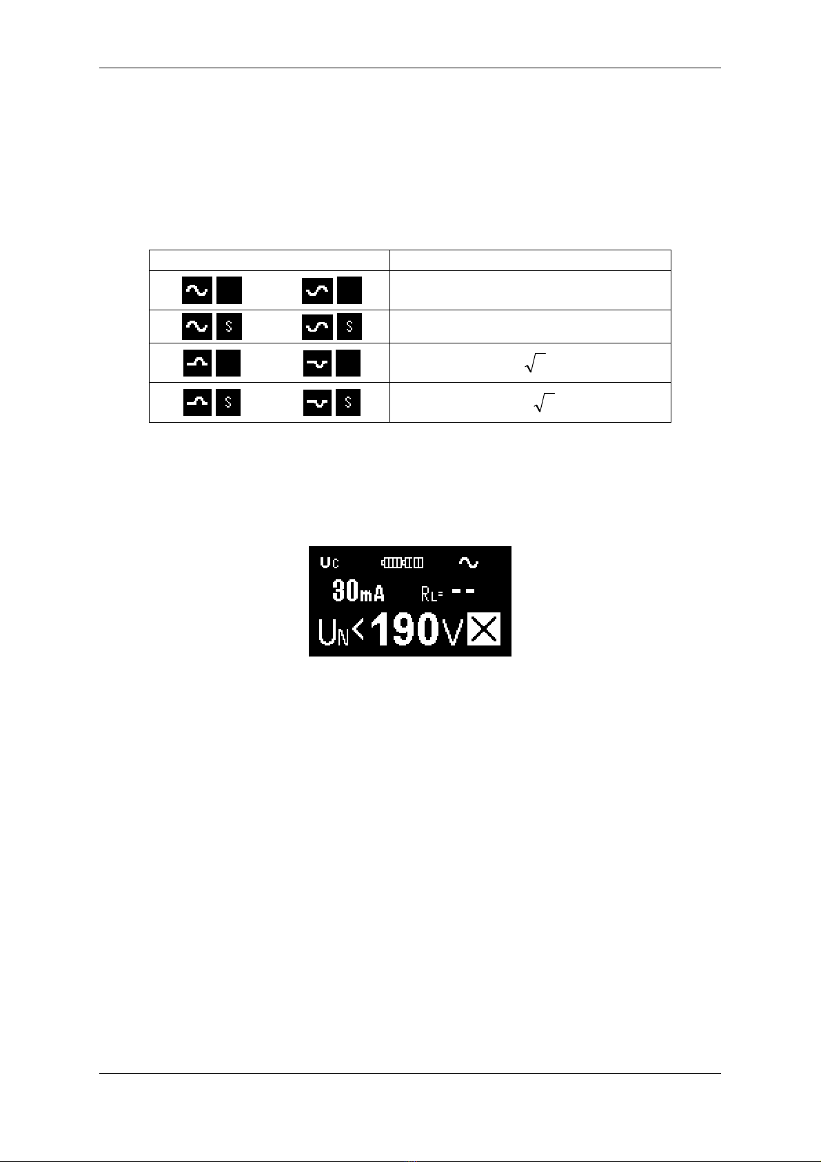
•If voltage applied on the test tips is < 190 V (consider also the note in the next
paragraph!) or > 255 V, the relevant information is displayed and the ST RT
utton does not start measurement:
Fig. 3.1a Voltage < 190 V Fig. 3.1b Voltage > 2 V
•If the fuse is lown, it is indicated on the display:
Fig. 3.2 The symbol of blown fuse
The fuse should e replaced as descri ed in the Chapter 4.1.

FITESTpro
-9-
Note:
If voltage applied on the test tips of the instrument with not blown fuse is in
range a out 25 V ÷ 190V, the instrument also displays the symbol of blown
fuse. Before replacing the fuse, therefore, make sure that voltage in
measured circuit in range 190 V ÷ 255 V.
•If voltage applied on the test tips is in range 190 V ÷ 255 V, TRMS value is
displayed and the ST RT utton can start the measurement:
Fig. 3.3 Example of voltage measurement
•For safety reasons the device each time after you press the ST RT key
efore measuring the desired RCD parameter first tests whether the contact
voltage Uc is higher than the set limit. If the contact voltage is higher, this
dangerous status is indicated and the measurement is not allowed:
Fig. 3.4a Contact voltage > 0 V Fig. 3.4b Contact voltage > 2 V
•If after starting the measurement y the ST RT key the sym ol of RCD trip-
out is displayed (Fig. 3.5), RCD tripped-out during contact voltage
measurement. This may e caused y ad I∆Nset, y faulty RCD or ecause
of a leakage current flow via RCD under test which adds up the differential
current generated y the instrument. This status is indicated until a key for
selecting function is pressed, or a new connection to mains voltage is done.
Fig. 3.5 Example of RCD trip-out during contact voltage measurement displaying

FITESTpro
- 10 -
•If attery is low (only red part of attery indicator is displayed), then you can’t
start the measurement y the ST RT key – after pressing it the low attery
sym ol is displayed for a while. Thereafter, the instrument goes into status
efore pressing the ST RT key. Battery must e replaced / accumulators
charged as descri ed in the Chapter 4.1.
Fig. 3.6a Indication of low battery Fig. 3.6b Low battery after the
START key was pressed
•If more consecutive measurements at higher values of I∆Nare done, the red
indicator showing the internal circuits of the instrument are hot can e
displayed. By the increasing temperature indicator’s area starts to expand. If
the maximal allowa le temperature has een exceeded, the STOP icon is
displayed and then you can’t start the measurement y the ST RT key –
after pressing it the overheating sym ol is displayed for a while. Thereafter,
the instrument goes into status efore pressing the ST RT key. Allow the
instrument to cool down. Cooling can e seen in the gradually narrowing
temperature indicator’s area.
Fig. 3.7a Indication of high
temperature
Fig. 3.7b High temperature after the
START key is pressed
•Current flowing in PE, caused for example y connected appliances or
capacities etween L and PE, may adversely affect the results of
measurements or measurement may e impossi le. Before the
measurements, therefore, remove such appliances / capacities.
•Before starting the measurement y the ST RT key relia ly connect the test
tips y the measured o ject. Next, check whether the displayed value of the
mains voltage is sta ilized. During the measurement neither early disconnect
the test leads nor interrupt the connection y the measured o ject. Doing so
may cause displaying of incorrect values.
FITESTpro
- 11 -
•Results may e adversely affected and measurement error exceeded:
If leakage current flows in PE (caused for example y connected appliances
or capacities etween L and PE), or if noise voltage/current is present in
grounding system or grounding system is affected y the potential of another
grounding system, or if mains voltage is unsta le during measurement.
•If the sym ol is displayed simultaneously y the measurement result, it
means that the main measured value result is within the required limits.
3.3. Pa amete s that can be set
•Limit contact voltage Ucmax can e set to 50 V or 25 V. Setting can e
done y the xI∆Nkey. Measurement function contact voltage Uc must e
selected.
•Nominal differential current can e set to 10 mA, 30 mA, 100 mA, 300 mA
or 500 mA y the xI∆Nkey. For more details see technical data in the Chapter
5.1.
•Multiplier of the nominal differential current can e set to ½, 1, 2 or 5 y
the xI∆Nkey. For more details see technical data in the Chapter 5.1.
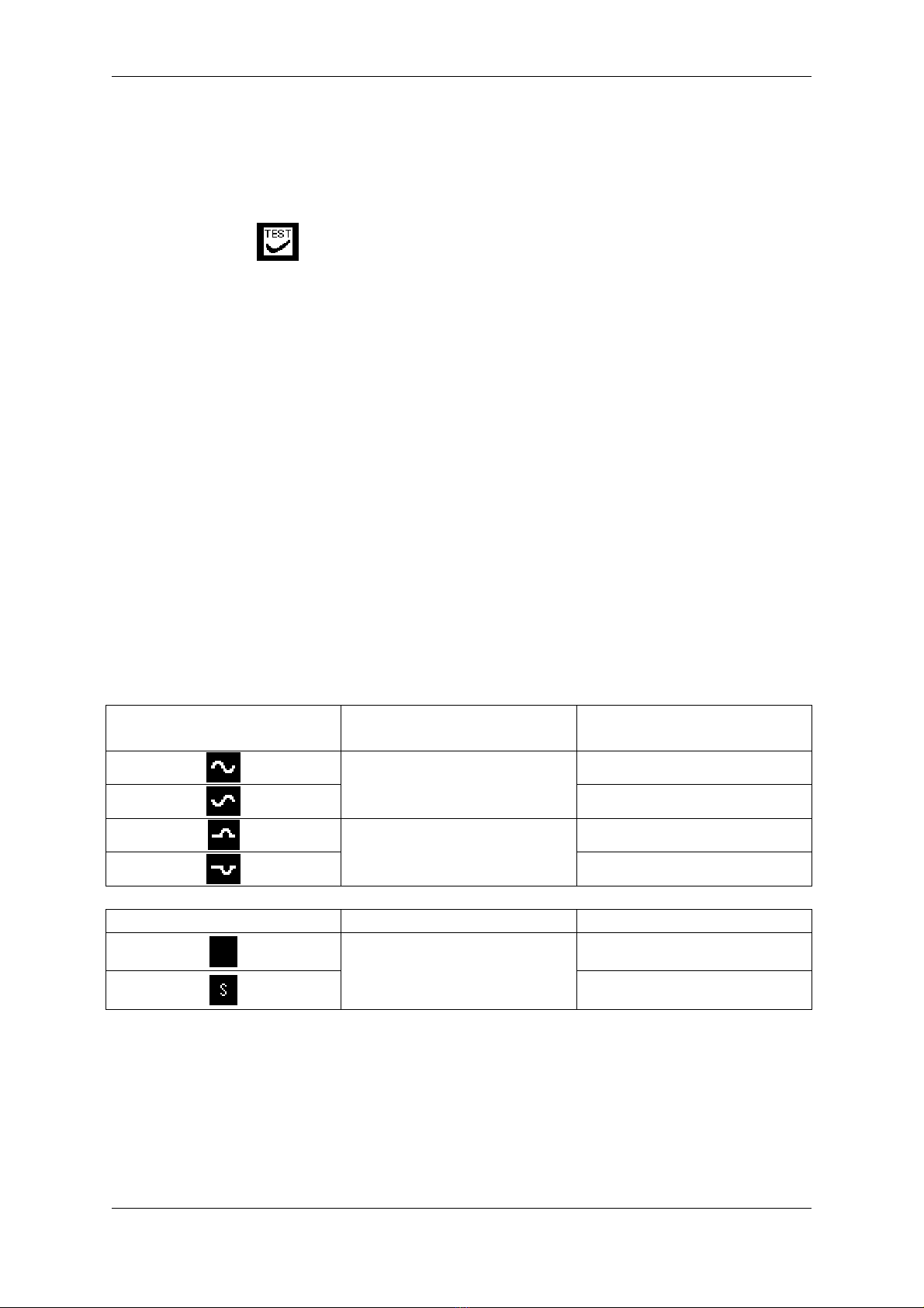
•RCD type and initial polarity of the differential current can e set y the
TYPE key.
Displayed sym ol RCD type (shape of the
differential current)
Initial polarity of the
differential current
Positive half-wave
AC (sine wave) Negative half-wave
Positive half-wave
A (pulsed) Negative half-wave
Displayed sym ol RCD type RCD type
Standard
AC or A
Selective
For more details see technical data in the Chapter 5.1.
FITESTpro
- 12 -
3.4. Measu ement of RCD pa amete s
3.4.1. Contact voltage Uc
Displayed contact voltage is related to the nominal differential current.
For security reasons, it is multiplied y a coefficient:
RCD type Contact voltage is proportional to:
1,05×I∆N
1,05×2×I∆N
1,05×㪉×I∆N
1,05×2x 㪉×I∆N
•Set Uc function y the FUNC key.
You can set the nominal differential current y the I∆Nkey.
You can set the RCD type y the TYPE key.
You can set the limit contact voltage Ucmax y the xI∆Nkey.
Fig. 3.8 Example of settings for contact voltage measurement
•Connect the instrument to RCD under test. Example of connection:

FITESTpro
- 13 -
Fig. 3.9 Example of connection
•After displayed mains voltage UL-PE is sta ilized, press and release the
ST RT key. Measurement will e carried out.
•Result is displayed afterwards:
Fig. 3.10 Example of contact voltage measurement result
RL.....Loop resistance; RL= Uc*/ I∆N,
where Uc* is actually measured value, i.e. no safety coefficient is used as
listed in the ta le at the eginning of this chapter.
Note: loop resistance is displayed if the nominal differential current I∆Nis set
to value ≥ 30 mA.
•Disconnect the instrument from RCD under test.
RCD under test

FITESTpro
- 14 -
3.4.2. Trip-out time TIME
Following ta le lists allowed trip-out times according to EN 61008 / EN 61009
and IEC 60364-4-41 standards:
½ I∆N* I∆N2 I∆N5 I∆NNote
Standard – 300 ms 150 ms 40 ms
– 500 ms 200 ms 150 ms
max. allowed
trip-out current
Selective – 130 ms 60 ms 50 ms min. allowed
trip-out current
* RCD must not trip-out.
•Set TIME function y the FUNC key.
You can set the nominal differential current y the I∆Nkey.
You can set the RCD type y the TYPE key.
You can set the multiplier of nominal differential current y the xI∆Nkey.
Fig. 3.11 Example of settings for trip-out time measurement
•Connect the instrument to RCD under test. Example of connection in Fig. 3.9.
•After displayed mains voltage UL-PE is sta ilized, press and release the
ST RT key. Measurement will e carried out.
•Result is displayed afterwards:
Fig. 3.12a Example of trip-out time
measurement result
Fig. 3.12b Example of measurement
result – RCD did not trip-out
Uc.....Contact voltage.
•Disconnect the instrument from RCD under test.

FITESTpro
- 15 -
Note: For safety reason, contact voltage is automatically measured efore trip-
out time is measured. As the selective type of RCDs include integrator, it is
necessary to wait some time efore the integrator sets to default. This is why the
measuring process inserts a pause 30 s for selective RCDs. The remaining time
is displayed as count down from 30 to 1:
Fig. 3.13 Example of count down for selective RCD
3.4.3. Trip-out current I
•Set Ifunction y the FUNC key.
You can set the nominal differential current y the I∆Nkey.
You can set the RCD type y the TYPE key.
Fig. 3.14 Example of settings for trip-out current measurement
•Connect the instrument to RCD under test. Example of connection in Fig. 3.9.
•After displayed mains voltage UL-PE is sta ilized, press and release the
ST RT key. Measurement will e carried out.
•Result is displayed afterwards:

FITESTpro
- 16 -
UcI.....Contact voltage at tripping current.
•Disconnect the instrument from RCD under test.
3.5. Othe functions of the inst ument
Phase (live) conductor test
If the sym ol is displayed in the lower right corner of the display, then the
connecting of the test tip on instrument’s case to phase (live) voltage (mova le
test tip has to e unconnected) causes a change of sym ol to sym ol L:
Fig. 3.16a Phase voltage not present
on the test tip
Fig. 3.16b Phase voltage present on
the test tip
Note: To avoid wrong results, following prerequisites must be met:
You have to hold the instrument in hand (palm) in a standard way!
You have to stand on non-insulated floor!
Phase voltage etween conductor under test and ground is ≥ 190 V / 45÷ 65 Hz.
Illumination of measurement point with white LED
LED can e switched on/off y riefly pressing and releasing the ST RT key.
Note: The test tips have to e without applied voltage!
How to display firmware version
The instrument has to e turned off and oth test tips disconnected from any
circuit!
Press the FUNC key and keep it pressed, then turn the instrument on. Firmware
version (e.g. v1.0.0 and possi ly additional service information) is displayed.
After releasing the keys the instrument enters the normal operating mode.
Fig. 3.15a Example of trip-out current
measurement result
Fig. 3.15b Example of measurement
result – RCD did not trip-out

FITESTpro
- 17 -
3.6. RESET of the inst ument
If the instrument does not work correctly as descri ed in this manual, we
recommend RESET:
The instrument has to e turned off and oth test tips disconnected from any
circuit! If you turn the instrument on and it will not restore its proper function, then
remove atteries – the procedure is descri ed in the Chapter 4.1., wait at least
10 s and insert set of new atteries. If proper function will not e restored, then
remove atteries again – the procedure is descri ed in the Chapter 4.1., put the
instrument out of operation and secure it against any unintended operation.
Contact service.

FITESTpro
- 18 -
4. MAINTENANCE
4.1. Batte ies and fuse eplacement
Dangerous voltage in batteries / fuse compartment!
Disconnect both test tips from tested object and turn off the
instrument before removing the batteries / fuse compartment
cover or before connecting jack to the socket for accumulator
charger!
The instrument must not be put into operation without the
batteries / fuse compartment cover properly fastened by both
screws!
The instrument uses four AAA either alkaline cells or NiCD/NiMH accumulators.
The atteries/accumulators are continuously monitored, see description in the
Chapter 3.2. If atteries/accumulators are low, it must e replaced/charged.
There is fuse under atteries / fuse compartment cover. If the fuse is lown, it is
indicated on the display, see Chapter 3.2.
4.1.1. Inserting and replacing the batteries / accumulators
Batteries/accumulators are inserted into the device y unscrewing two screws
and removing the atteries / fuse compartment cover, see Fig. 2.2. Then remove
old atteries/accumulators and insert new ones. O serve correct polarity:
Fig. 4.1 Correct batteries/accumulators polarity and the fuse location
Always replace all four atteries/accumulators. Use only high-quality types.

FITESTpro
- 19 -
Then put the atteries / fuse compartment cover ack and secure it with two
screws.
4.1.2. Charging of accumulators
For charging of accumulators use only adapter supplied as
optional accessories!
Accumulators are charged as soon as the adapter is connected to mains and to
socket for accumulators charger (see Fig. 2.1). If accumulators are fully
discharged, the charging takes a out 6 hours (applies to atteries with a
capacity of 800 mAh). Prolonged charging is not a pro lem, however, do not
charge accumulators for more than 12 hours.
Notes:
•Do not charge alkaline cells – it may lead to explosion, leakage, etc. This can
cause serious damage or destruction of instrument.
•During charging of new accumulators or ones that were unused for a longer
period (few months) unpredicta le chemical processes may arise. As a result,
the instrument operation time can e significantly reduced. In this case, we
recommend several charge (with optional charger) / discharge (normal use of
the instruments) cycles.
Another way is to use a stand-alone intelligent charger which discharge /
charge each cell individually. The discharge / charge cycle is automatically
executed, see instruction manual for the charger used.
After the procedure, the capacity of the accumulators should return to normal.
The a ove descri ed cycle in stand-alone intelligent charger is recommended
every few months to make.
•If after several cycles of the a ove descri ed discharge / charge capacity of
the accumulators does not return to normal, this may e due to the fact that
the one or more accumulators are degraded - whereas, the uilt-in
accumulator charger charges all cells connected in series at the same time,
and even one ad (or just different) cell negatively affects the entire
accumulator pack.
It may result in uneven charging of cells, excessive heating of the cell(s)
during charging etc.
In this case, we recommend that a faulty cell is identified with an intelligent
stand-alone charger, or at least comparing the voltage of each cell and then a
faulty cell replace with a new one.
•The above-described effects can not be confused with a normal reduction in
accumulators’ capacity over time. All accumulators with a rowin number of
char e / dischar e cycles radually loose capacity. This is normal, dependin on
accumulator type, the number and parameters of the dischar e / char e cycles.
Table of contents
Other ILLKO Circuit Tester manuals


