ILLUMINARC ilumiline 21g2 ip optic rgb User manual

Ilumiline 21g2 IP Optic RGB
User Manual

Edition Notes
Ilumiline 21g2 IP Optic RGB User Manual Rev. 4
Edition Notes
The Ilumiline 21g2 IP Optic RGB User Manual Rev. 4
covers the description, safety
precautions, installation, programming, operation, and maintenance of the
Ilumiline 21g2 IP
Optic RGB. ILUMINARC released this edition of the Ilumiline 21g2 IP Optic RGB User
Manual Rev. 4 in April 2018.
Trademarks
The ILUMINARC
logo, the ILUMINARC name and all other trademarks in this document
related to services or products by ILUMINARC are trademarks ow
ned or licensed by
ILUMINARC, its affiliates or subsidiaries. Any other
product names, logos, brands, company
names,
trademarks featured or referred to within this document are the property of their
respective trademark holders.
Copyright Notice
The entire content of this document, except where applicable and unless otherwise noted, is
solely owned by ILUMINARC, a wholly owned trademark of Chauvet & Sons, LLC.
© Copyright 2018 ILUMINARC.
All rights reserved.
Electronically published by ILUMINARC in the United States of America.
Manual Usage
ILUMINARC authorizes its customers to download and print this manual for professional
information purposes only. ILUMINARC expressly prohibits the u
sage, copy, storage,
distribution, modification,
or printing of this manual or its content for any other purpose
without its written consent.
Document Printing
For better results, print this document in color, on letter size paper (8.5 x 11 in), double-sided.
If using A4 paper (
210 x 297 mm), configure your printer to scale the content of this document
to A4 paper.
Intended Audience
Any person in charge of installing, operating, and/or maintaining the
Ilumiline 21g2 IP Optic
RGB should read all of both the guide that shipped with it and this User M
anual before
installing, operating, or maintaining this product.
Disclaimer
ILUMINARC believes that the information contained in this manual is accurate in all respects.
However, ILUMINARC assumes no responsibility for any error or omiss
ions in this document.
ILUMINARC reserves the right to revise this document and to make changes from time to time
in the content hereof without obligation of ILUMINARC to notify any person or company of
such revision or changes. This does not constitute in
any way a commitment by ILUMINARC
to make such changes. ILUMINARC may issue a revision of this manual or a new edition of it
to incorporate such changes.
Document Revision
The Ilumiline 21g2 IP Optic RGB User Manual Rev. 4 supersedes all previous versions of this
manual. Please discard any older versions of this manual you may have, whether in printed or
electronic format, and replace them with this version.

Table of Contents
Ilumiline 21g2 IP Optic RGB User Manual (Rev. 4) I
Table of Contents
1. Introduction ...................................................................................................1
What Is In The Box....................................................................................................... 1
Unpacking Instructions................................................................................................. 1
Claims .................................................................................................................................1
Text Conventions ......................................................................................................... 1
Safety Notes................................................................................................................. 2
Personal Safety...................................................................................................................2
Mounting and Installation.....................................................................................................2
Power and Wiring................................................................................................................2
Operation.............................................................................................................................2
2. Product Description......................................................................................3
Features ....................................................................................................................... 3
Additional Features..............................................................................................................3
Options................................................................................................................................3
Overview....................................................................................................................... 4
Dimensions................................................................................................................... 5
3. Installation.....................................................................................................6
Mounting....................................................................................................................... 6
Orientation...........................................................................................................................6
Installation...........................................................................................................................6
Procedure............................................................................................................................6
AC Power ..................................................................................................................... 7
Power Consumption............................................................................................................7
AC Plug ...............................................................................................................................7
Power Wiring.......................................................................................................................7
DMX Linking................................................................................................................. 8
DMX Modes.........................................................................................................................8
Signal Wiring .......................................................................................................................8
Protocol Connectivity...........................................................................................................8
Controllers.................................................................................................................... 9
DMX Controller....................................................................................................................9
ILUMICON.........................................................................................................................10
ILUMICODE ADDRESSER ...............................................................................................10

Table of Contents
II Ilumiline 21g2 IP Optic RGB User Manual (Rev. 4)
4. Operation.....................................................................................................11
ILUMICODE ADDRESSER........................................................................................ 11
Ilumicode Panel Description..............................................................................................11
Control Options .......................................................................................................... 11
Programming.............................................................................................................. 11
DMX Personality................................................................................................................11
DMX Starting Address.......................................................................................................11
Static Colors......................................................................................................................12
Dimmer..............................................................................................................................12
Color..................................................................................................................................12
Whites Setting ...................................................................................................................12
Reset to Factory Settings..................................................................................................12
Menu Map .................................................................................................................. 13
DMX Values ............................................................................................................... 14
ARC FULL.........................................................................................................................14
ARC 1................................................................................................................................14
ARC 1 + D.........................................................................................................................14
SOLID................................................................................................................................14
5. Technical Information................................................................................. 15
Product Maintenance ................................................................................................. 15
Product Repairs.......................................................................................................... 15
Troubleshooting Guide............................................................................................... 16
Photometrics .............................................................................................................. 17
LED Disclaimer........................................................................................................... 18
LED Life.............................................................................................................................18
LED Binning.......................................................................................................................18
Color Rendering Index (CRI).............................................................................................18
Returns Procedure..................................................................................................... 19
Technical Specifications............................................................................................. 20
Introduction
Ilumiline 21g2 IP Optic RGB User Manual (Rev. 4) 1
1. Introduction
Critical
installation,
configuration, or
operation information.
Failure to comply with this
information may render
the product partially or
completely inoperative,
damage third-party
equipment, or cause harm
to the user
Important
installation or
configuration
information. Failure to
comply with this
information may prevent
the product from
functioning correctly.
Useful
information.
The term “DMX”
used throughout
this document
refers to the USITT
DMX512-A transmission
protocol.
What Is In The Box
•Ilumiline 21g2 IP Optic RGB
•Warranty Card
•Quick Reference Guide
Unpacking Instructions
Immediately upon receiving a product from ILUMINARC, carefully unpack the carton. Check
the contents of the box to ensure that all parts are present and that they are in good condition.
Claims
The carrier is responsible for any damage incurred during shipping. Therefore, if the
received merchandise appears to have been damaged during shipping, the customer
must submit the damage report and any related claims to the carrier, not
ILUMINARC. The customer must submit the report upon receipt of the damaged
merchandise. Failure to do so in a timely manner may invalidate the customer’s claim
with the carrier.
For other issues such as missing components or parts, damage not related to shipping,
or concealed damage, the customer must make claims to ILUMINARC within 7 days
of receiving the merchandise.
Text Conventions
Convention
Meaning
1~512
A range of values in the text
50/60
A set of mutually exclusive values in the text
“ILUMICON UM”
The name of another publication or manual
<SET>
A button on the product’s control panel
Settings
A product function or a menu option
MENU > Settings
A sequence of menu options
1~10
A range of menu values from which to choose in a menu
Yes/No
A set of two mutually exclusive menu options in a menu
ON
A unique value to enter or select in a menu

Introduction
2 Ilumiline 21g2 IP Optic RGB User Manual (Rev. 4)
There are no
user-serviceable
parts inside this
product. Any reference to
servicing you may find in
this User Manual will only
apply to properly certified
ILUMINARC technicians.
Do not open the housing
or attempt any repairs
unless you are certified to
do so.
Refer to all
applicable local codes
and regulations for the
proper installation of this
product.
Keep this manual
for future consultation. If
you sell this product to
another user, make sure
that they also receive this
manual.
In the unlikely
event that your
Ilumiline 21g2 IP Optic
RGB may require service,
contact ILUMINARC
Customer Support.
Safety Notes
Please read all the following Safety Notes carefully because they include important information
on how to install, use, and maintain this product safely.
Personal Safety
•Avoid direct eye exposure to the light source while the product is on.
•Always disconnect this product from its power source before servicing.
•Always connect this product to a grounded circuit to avoid the risk of electrocution.
•Do not touch this product’s housing when operating because it may be very hot.
Mounting and Installation
•DO NOT submerge this product (IP66). Regular outdoor operation is fine.
•This product weighs 7 lbs (3.18 kg). Always ask for help when mounting this product
to avoid personal injuries or damage to the product.
•Make sure there are no flammable materials close to this product while it is operating.
•CAUTION: When transferring product from extreme temperature environments,
(e.g. cold truck to warm humid ballroom) condensation may form on the internal
electronics of the product. To avoid causing a failure, allow product to fully acclimate
to the surrounding environment before connecting it to power.
•When hanging this product, always secure it to a fastening device using a safety cable.
Power and Wiring
•Always make sure that you are connecting this product to the proper voltage, as per the
specifications in this manual or on the product’s sticker.
•Never connect this product to a dimmer pack.
•Make sure that the power input cable is not cracked, crimped, or damaged.
•Never disconnect this product by pulling or tugging on the power input cable.
Operation
•The maximum ambient temperature is 113° F (45° C). Do not operate this product at a
higher temperature.
•In case of a serious operating problem, stop using this product immediately!

Product Description
Ilumiline 21g2 IP Optic RGB User Manual (Rev. 4) 3
2. Product Description
The Ilumiline 21g2 IP Optic RGB is a linear wash product that may be used to light a variety of
both indoor and outdoor applications.
The Ilumiline 21g2 IP Optic RGB consists of the main housing and two surface mounting
brackets. The DMX input and output is located on rear of the product.
Features
•1, 3, 4, or 7-channel RGB LED linear wash product
•Operating modes:
1-channel: Dimmer
3-channel: RGB control
4-channel: RGB, dimmer
7-channel: RGB, dimmer, color macro, strobe, dimmer speed
•RGB color mixing with or without DMX control
•Color temperature presets (3,200~10,000 K)
•Built-in automated programs via DMX
•IP66 stainless steel gland nuts for cable entry
•Integrated Cooling Enhancement™
Additional Features
•Adjustable bracket
•Humidity-controlling GORE valve
•Impact-resistant glass lens cover
•Cast aluminum, IP66 housing
•5 distinct dimming curves
Options
•ILUMICODE ADDRESSER (for product configuration)
•The RDM2go, which includes a built in ilumicode addresser along with many other useful
features is now available.
•
The Ilumicoode addresser is required for product configuration (sold separately).

Product Description
4 Ilumiline 21g2 IP Optic RGB User Manual (Rev. 4)
Overview
GORE valve
Data In/Out
Power In
Mounting
Brackets

Product Description
Ilumiline 21g2 IP Optic RGB User Manual (Rev. 4) 5
Dimensions
Installation
6 Ilumiline 21g2 IP Optic RGB User Manual (Rev. 4)
3. Installation
Make sure to
mount this product
away from any
flammable material as
indicated in the Safety
Notes.
Mounting
Before mounting this product, read and follow the safety recommendations indic
ated in the
Safety Notes.
Orientation
Always mount this product in a safe position, making sure there is adequate room for
ventilation, configuration, and maintenance.
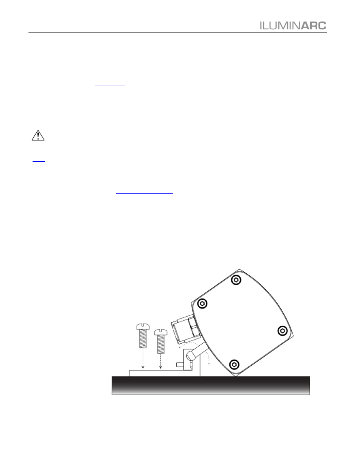
Installation
The Ilumiline 21g2 IP Optic RGB comes with two adjustable brackets with 3 mm slot
openings to mount the product on any firm, non-flammable surface. Once mounted the
angle of the product can also be adjusted and locked into place. ILUMINARC
recommends following the general guidelines below when mounting the Ilumiline 21g2
IP Optic RGB.
•When selecting an installation location, consider ease of access to the product for
operation, programming adjustments and routine maintenance.
•Make sure the product’s mounting location can support its weight. Please see the
Technical Specifications section of this manual for the weight requirement of this
product.
Procedure
The Ilumiline 21g2 IP Optic RGB comes with two adjustable brackets with 3 mm slot
openings to mount the product on any firm, non-flammable surface. These feet also
serve as floor or wall mount supports. You will have to use two mounting points per
product.
Installation
Ilumiline 21g2 IP Optic RGB User Manual (Rev. 4) 7
Always connect
the Ilumiline
21g2 IP Optic
RGB to a protected circuit
with an appropriate
electrical ground to avoid
the risk of electrocution or
fire.
Never connect
the Ilumiline 21g2
IP Optic RGB to a
rheostat (variable resistor)
or dimmer circuit, even if
the rheostat or dimmer
channel serves only as a
0% to 100% switch.
Make sure to
connect the
Ilumiline 21g2 IP
Optic RGB to a power line
with the proper voltage
and frequency, as per the
specifications in this
manual or on the
product’s sticker.
AC Power
The Ilumiline 21g2 IP Optic RGB has an auto-ranging power supply that works with an input
voltage range of 100~240 VAC, 50/60 Hz.
Make sure that you are connecting this product to the proper voltage, as per the specifications in
this User Manual or on the product’s sticker.
Power Consumption
To determine the power requirements for the Ilumiline 21g2 IP Optic RGB, refer to
the label affixed to the side of the product. You may also refer to the Technical
Specifications.
The listed current rating indicates the maximum current draw during normal operation.
AC Plug
The Ilumiline 21g2 IP Optic RGB comes with a bare-ended power input cord for
hardwire installation. Use the table and the illustration below to wire a plug.
Connection
Wire (U.S.)
Screw Color (U.S.)
Wire (Europe)
IP66 Pin
AC Live
Black
Yellow or Brass
Brown
1
AC Neutral
White
Silver or Gray
Blue
2
AC Ground
Green/Yellow
Green
Green/Yellow
3
The listed current
rating indicates
the maximum
current draw
during normal operation.
If you choose to
bury the power or
signal distribution
boxes, make sure that
they are IP66-rated or
greater.
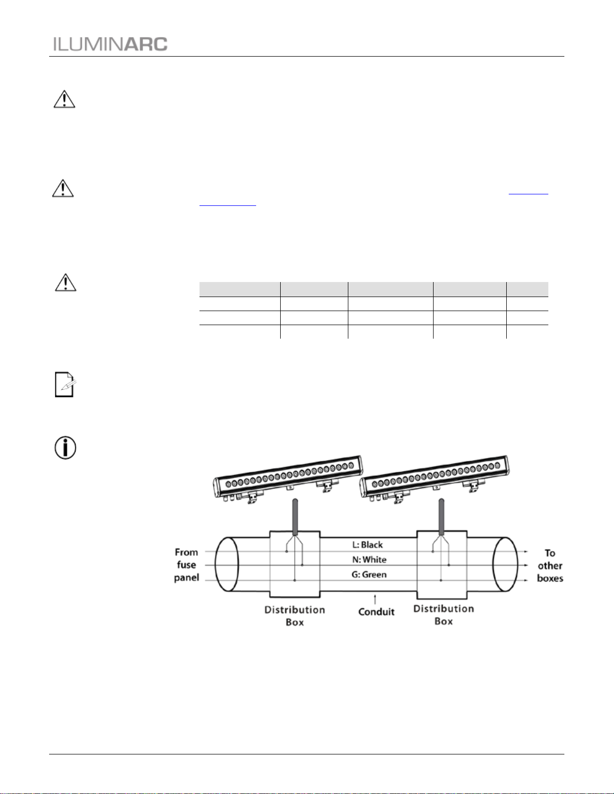
Power Wiring
You can connect the bare-ended, IP66-rated AC power cable from the product to an
IP66-rated power connector or IP66-rated junction box.
If using junction boxes, make sure to use IP66-rated conduit for surface installations.

Installation
8 Ilumiline 21g2 IP Optic RGB User Manual (Rev. 4)
The Ilumiline
21g2 IP Optic
RGB must be
linked using
DMX cable in a daisy
chain (serial) fashion. To
comply with the EIA-485
standard, no more than
32 products should be
connected on one daisy
chain without using a
DMX optically isolated
splitter. Doing otherwise
may result in deterioration
of the digital DMX signal.
USITT
recommends
limiting the total length of
the DMX cable (from the
first product/controller to
the last product) to
300~455 m (985~1,500
ft).
Disconnect the
product from the
AC power before opening
it.
The signal cable
must match or
exceed the electrical
characteristics of the
Belden 9841 cable for
EIA RS-485 applications.
You may also use CAT5,
5e, or CAT6 LAN cable.
DMX Linking
You may link the Ilumiline 21g2 IP Optic RGB to a DMX controller using a standard DMX
serial connection. If using other DMX products compatible with the Ilumiline 21g2 IP Optic
RGB, you can control each individually with a single DMX controller.
If you are not familiar with the DMX standard, or if you need information about the DMX cables
needed to link the Ilumiline 21g2 IP Optic RGB to a DMX controller, you may download the
“DMX Primer” from the ILUMINARC w
ebsite at
http://www.iluminarc.com/download/DMX_Primer.pdf.
DMX Modes
The Ilumiline 21g2 IP Optic RGB uses the standard DMX data connection for its all its
DMX personalities. Refer to the Introduction chapter for a brief description of these
modes. Refer to the Operation chapter to learn how to configure the Ilumiline 21g2 IP
Optic RGB to work in these modes. The DMX Values section provides detailed
information regarding the DMX modes.
DMX Mode
DMX Address
ARC FULL
506
ARC1
510
ARC1+D
509
SOLID
512
Signal Wiring
To provide signal for the Ilumiline 21g2 IP Optic RGB, you can connect the bare-ended,
IP66-rated signal cable from the product to two IP66-rated signal connectors (DMX
In/DMX Out) or use an IP66-rated junction box. In this case, make sure to use
IP66-rated conduit.
Protocol Connectivity
The Ilumiline 21g2 IP Optic RGB uses USITT DMX 512 protocol. The procedure
below illustrates the recommended connection method.
Installation
Ilumiline 21g2 IP Optic RGB User Manual (Rev. 4) 9
If you have not
configured the
DMX starting
address and
DMX mode for each
product, they will all use
their default values. This
means that all products
will operate in unison.
Controllers
The Ilumiline 21g2 IP Optic RGB can operate with a standard DMX controller or the
ILUMICODE ADDRESSER. The sections below provide information on how to connect these
products to the corresponding controllers. The instructions to operate these products with each of
the above controllers are in the Operation chapter of this manual.
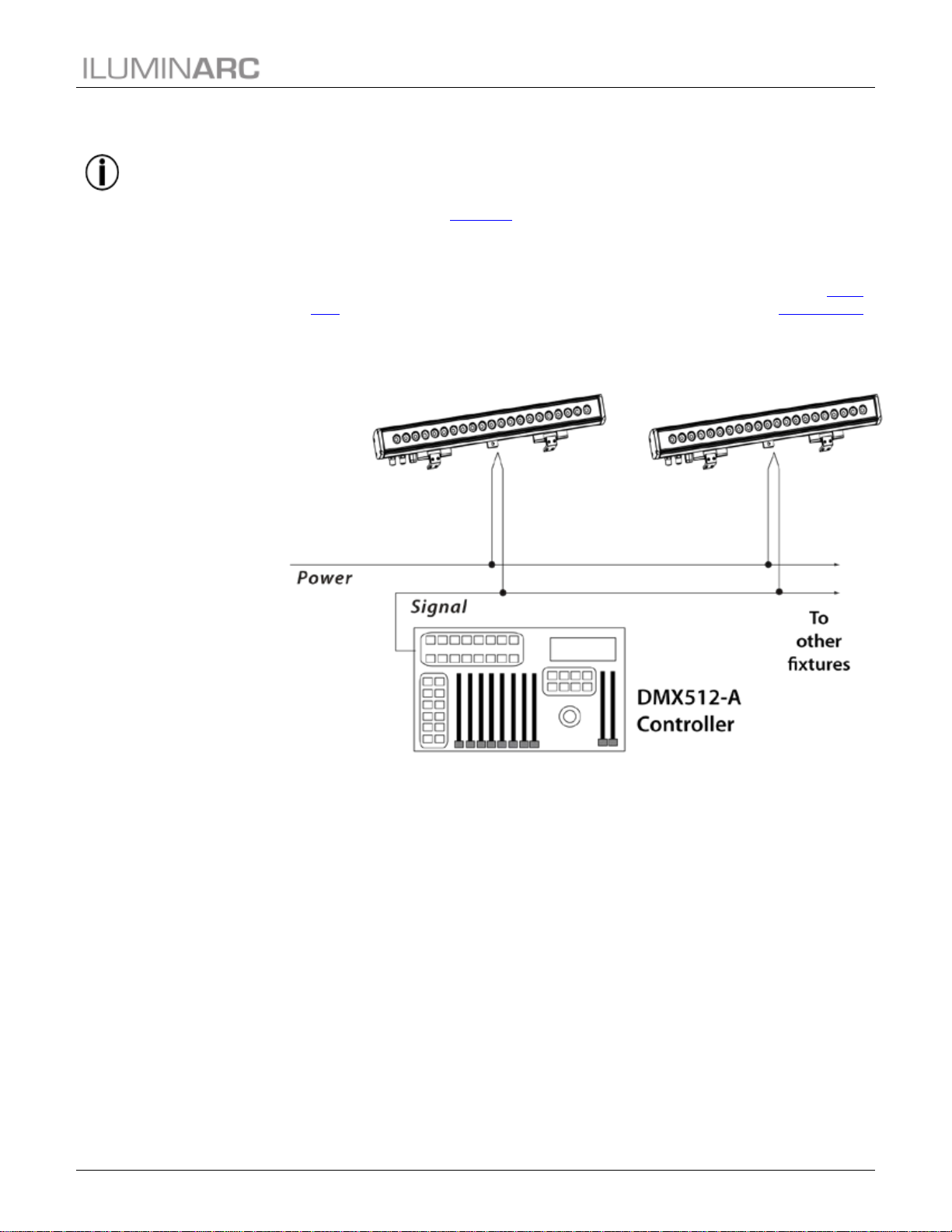
DMX Controller
The Ilumiline 21g2 IP Optic RGB can work with a standard DMX controller. The
channel assignments will depend on the chosen personality (see the corresponding Menu
Map section) and the DMX address assigned to each product (see the Programming
section).
The figure below illustrates how to connect the DMX controller to the Ilumiline 21g2 IP
Optic RGB.

Installation
10 Ilumiline 21g2 IP Optic RGB User Manual (Rev. 4)
The RDM2go,
which includes a
built in ilumicode
addresser along with many
other useful features is
now available.
To assign
individual DMX
addresses to each
product, you must
connect the ILUMICODE
ADDRESSER to each
product, individually.
ILUMINARC
suggests that you
connect no more
than 20 products
in this mode and keep the
total distance to less than
60 m (197 ft). Otherwise,
you might need to use an
optically isolated signal
amplifier.
ILUMICON
The Ilumiline 21g2 IP Optic RGB can also work with the ILUMICON controller instead
of a standard DMX controller. Please refer to the ILUMICON User Manual to learn how
to use this controller with the Ilumiline 21g2 IP Optic RGB.
The figure below illustrates how to connect the ILUMICON controller to the Ilumiline
21g2 IP Optic RGB.
ILUMICODE ADDRESSER
The Ilumiline 21g2 IP Optic RGB uses the ILUMICODE ADDRESSER (“Ilumicode”)
for configuration purposes. The diagram below shows how to connect the Ilumicode to
this product. This connection will control multiple products at the same time, all having
the same DMX address.
Important: The RDM2go, which includes a built in ilumicode addresser along with many
other useful features is now available. The Ilumicode must be used to configure this
product. The Ilumicode or RDM2go can be purchased separately.
Operation
Ilumiline 21g2 IP Optic RGB User Manual (Rev. 4) 11
4. Operation
When you scroll
through the
menu options,
you will see
many of them that do not
correspond with the menu
map. Skip them, as they
do not work with the RGB
only output products.
ILUMICODE ADDRESSER
The Ilumiline 21g2 IP Optic RGB needs an external controller, such as the ILUMICODE
ADDRESSER (“Ilumicode”), or RDM2go to change its configuration.
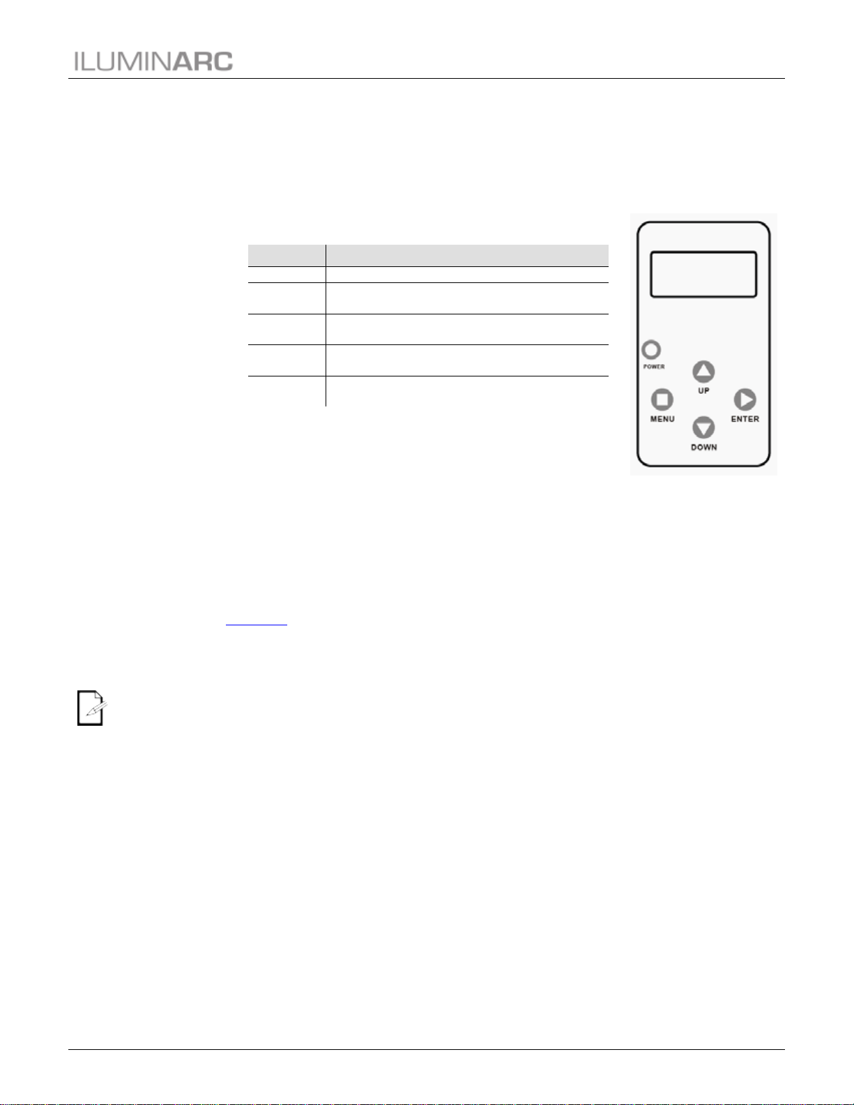
Ilumicode Panel Description
Control Options
You can set the Ilumiline 21g2 IP Optic RGB starting address in the 001~512 DMX range. This
allows for the control of up to 73 products in the 7-channel ARC FULL personality.
Programming
Carry out all the programming procedures indicated below from the control panel. Refer to the
Menu Map section to learn how the menu options relate to each other.
Use <ENTER> and <MENU> to change levels in the Menu Map, moving right and left
respectively. Use <UP> and <DOWN> to move vertically within the Menu Map.
DMX Personality
1. Go to PERSON and select any DMX personality.
2. Make sure to rearrange the DMX addresses of all products in the current DMX
universe to avoid address overlapping.
DMX Starting Address
1. Go to DMX.
2. Select a starting DMX address (001~512).
Button
Function
<MENU>
Exits from the current menu or function
<ENTER>
Enables the currently displayed menu or sets the
currently selected value into the selected function
<UP>
Navigates upwards through the menu list and increases
the numeric value when in a function
<DOWN>
Navigates downwards through the menu list and
decreases the numeric value when in a function
<POWER>
Turns the unit on. The unit will turn off automatically
after 30 seconds of inactivity

Operation
12 Ilumiline 21g2 IP Optic RGB User Manual (Rev. 4)
DIM1 is the
fastest dimming
curve and DIM4
is the slowest.
Static Colors
1. Go to STATIC.
2. Select a color or effect (RED, GREN, BLUE, or STRB).
3. Select a color value (000~255) or a strobe frequency (00~20).
Dimmer
This setting gives the user four different options to simulate the dimming curve of an
incandescent lighting product.
1. Go to DIMMER.
2. Select a dimming curve (OFF or DIM1~4).
Procedure:
DIMMER
Description
OFF
Dimmer curve is linear with fader
DIM1
Non-linear (fastest)
DIM2
Non-linear (fast)
DIM3
Non-linear (slow)
DIM4
Non-linear (slowest)
Color
1. Go to SETTINGS > COLOR.
2. Select the color method (OFF, RGBTOW, or UC).
Details:
OFF
When the RGB faders are all set to “255”, the output is maximum.
RGBTOW
When the RGB faders are all set to “255”, the output is the selected White color
(see Whites Setting).
UC
When the RGB faders are all set to “255”, the output matches the same color
output of previous versions of this product.
Whites Setting
1. Go to CALIB.
2. Select a white color (WHITE 1~11) or RGB TO W.
3. Select an RGB color (RED, GREN, or BLUE).
4. Configure the color value (000~255).
5. Repeat steps 3 and 4 for the other RGB colors to obtain a white color.
6. Repeat steps 2 through 5 for the other white colors.
Resetto Factory Settings
1. Go to SETTINGS > RESET.
2. Select an option (YES/NO).

Operation
Ilumiline 21g2 IP Optic RGB User Manual (Rev. 4) 13
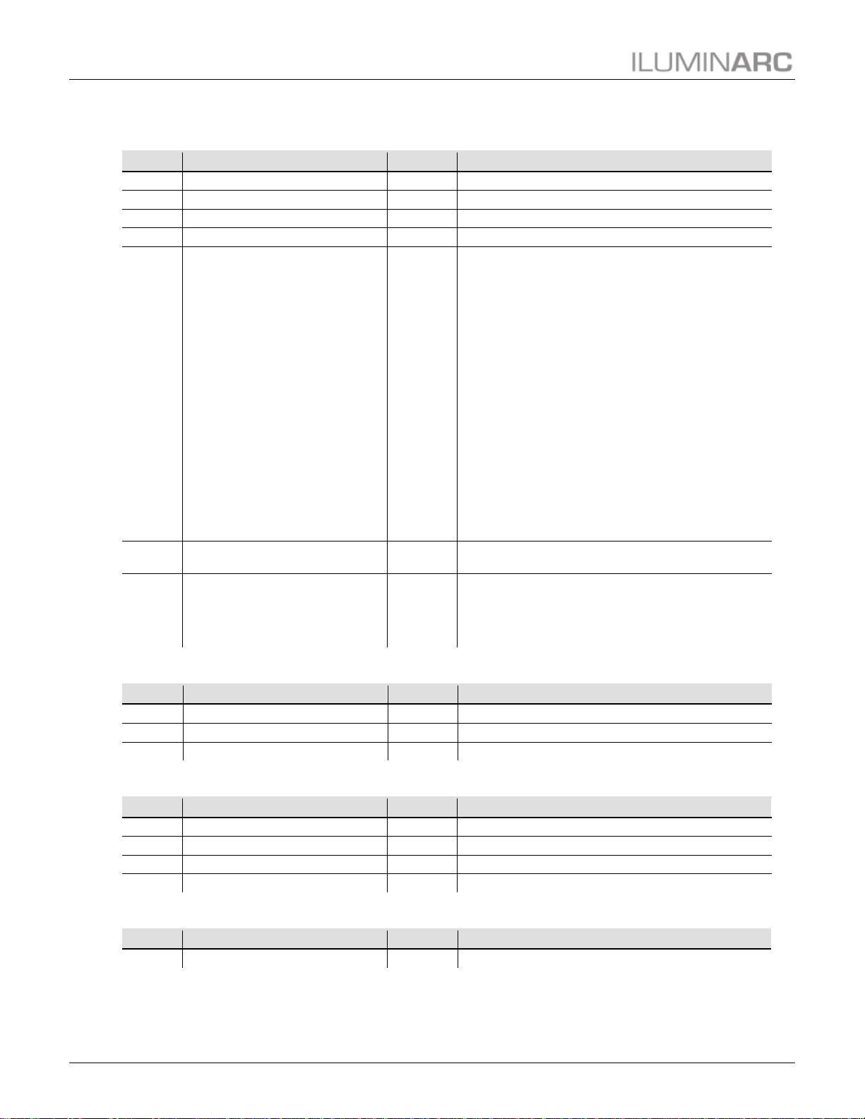
Menu Map
Main Level
Programming Levels
Description
DMX
001~512
N/A
Sets the DMX starting address
PERSON
ARC 1
N/A
3-channel: RGB control
ARC 1 + D
4-channel: RGB control + dimmer
ARC FULL
7-channel: RGB control, dimmer, color macro, strobe,
dimmer speed
REMOTE
Allows use of the ILUMICON
SOLID
1-channel: dimmer
CALIB
WHITE (1~11)
RED
GREN
BLUE
000~255
Determines the white balance for the color macros
RGBTOW
Determines the white balance when RGBTOW is
active
DIMMER
OFF
N/A
Dimmer works in linear mode
DIM 1
Dimmer works in non-linear mode, from fast to slow
DIM 2
DIM 3
DIM 4
STATIC
RED
000~255
Configures the static color and effects
GREN
BLUE
STRB
SETTINGS
COLOR
OFF
Maximum output, unbalanced white
RGBTOW
White output is as per CALIB > RGBTOW settings
UC
Output matches that of product’s previous versions
RESET
NO/YES
Resets unit to factory default settings
Operation
14 Ilumiline 21g2 IP Optic RGB User Manual (Rev. 4)
DMX Values
ARC FULL
Channel
Function
Value
Percent/Setting
1
Dimmer
000 ó255
0~100%
2
Red
000 ó255
0~100%
3
Green
000 ó255
0~100%
4
Blue
000 ó255
0~100%
5 Color Macros
000 ó010
011 ó030
031 ó050
051 ó070
071 ó090
091 ó110
111 ó130
131 ó150
151 ó170
171 ó200
201 ó205
206 ó210
211 ó215
216 ó220
221 ó225
226 ó230
231 ó235
236 ó240
241 ó245
246 ó250
251 ó255
No function
R: 100% G: 0~100% B: 0
R: 100%~0 G: 100% B: 0
R: 0 G: 100% B: 0~100%
R: 0 G: 100%~0 B: 100%
R: 0~100% G: 0 B: 100%
R: 100% G: 0 B: 100%~0
R: 100% G: 0~100% B: 0~100%
R: 100%~0 G: 100%~0 B: 100%
R: 100% G: 100% B: 100%
White 1
White 2
White 3
White 4
White 5
White 6
White 7
White 8
White 9
White 10
White 11
6 Strobe
000 ó009
010 ó255
No function
Slow~Fast
7 Dimmer Speed
000 ó009
010 ó069
070 ó129
130 ó189
190 ó255
Off
Speed 1 (Fastest)
Speed 2
Speed 3
Speed 4 (Slowest)
ARC 1
Channel
Function
Value
Percent/Setting
1
Red
000 ó255
0~100%
2
Green
000 ó255
0~100%
3
Blue
000 ó255
0~100%
ARC 1 + D
Channel
Function
Value
Percent/Setting
1
Dimmer
000 ó255
0~100%
2
Red
000 ó255
0~100%
3
Green
000 ó255
0~100%
4
Blue
000 ó255
0~100%
SOLID
Channel
Function
Value
Percent/Setting
1
Dimmer
000 ó255
0~100%
Technical Information
Ilumiline 21g2 IP Optic RGB User Manual (Rev. 4) 15
5. Technical Information
Always dry the
external optics
and glass
surfaces carefully
after cleaning them.
If you still
experience
technical
problems after
trying the solutions in the
Troubleshooting Table,
contact ILUMINARC
Technical Support.
Product Maintenance
To maintain optimum performance and minimize wear, clean the products frequently. Usage
and environment are contributing factors in determining the cleaning frequency. As a general
guideline, products should be cleaned at least twice a month. Dust build-up reduces light output,
performance, and can cause overheating. This can lead to reduced light source life.
For products containing external optical lenses, clean them periodically to optimize light output.
The cleaning frequency depends on the environment in which the product operates. Damp,
smoky, or particularly dirty surrounding can cause greater accumulation of dirt on the product’s
optics, requiring more frequent cleaning.
To clean a product:
•Unplug the product from power.
•Wait until the product has cooled.
•Use a vacuum (or dry compressed air) and a soft brush to remove dust collected on the
external vents and reachable internal components.
•Clean all external glass optics and glass surfaces with a mild solution of glass cleaner
or isopropyl alcohol, and a soft, lint-free cotton cloth or lens-cleaning tissue.
•Apply the solution directly to the cloth or tissue and wipe any dirt and grime to the
outside edge of the lens.
•Gently polish the external glass surfaces until they are free of haze and lint.
Product Repairs
ILUMINARC strongly advises you against attempting any repairs to this product unless you are
an authorized ILUMINARC technician.
ILUMINARC presents the information contained in the Troubleshooting Guide as potential
solutions only. In most cases, opening the product’s housing will invalidate its warranty.

Technical Information
16 Ilumiline 21g2 IP Optic RGB User Manual (Rev. 4)
Troubleshooting Guide
Symptom Cause(s) Action(s)
Circuit breaker/fuse keeps
tripping/blowing
Excessive circuit load
Check total load placed on the electrical
circuit
Short circuit along the power wires
Check for a short in the electrical wiring
Product does not power up
No power
Check for power on power outlet
Loose or damaged power cord
Check power cord
Faulty internal power supply
Return for service to ILUMINARC
Product does not respond to
DMX
Wrong DMX addressing
Check Control Panel and product addressing
Damaged DMX cables
Check DMX cables
Wrong polarity on the controller
Check polarity switch settings on the
controller
Loose DMX cables
Check cable connections
Faulty DMX interface
Return for service to Iluminarc
Faulty Display/Main board
Return for service to Iluminarc
DMX signal problems
Non-DMX cables
Use only DMX-compatible cables
Bouncing signals
Install terminator as suggested in the “DMX
Primer” from the ILUMINARC website at
http://www.iluminarc.com/download/DMX_
Primer.pdf
Long cable/low level signal
Install an optically coupled DMX splitter
right after the product with the strong signal
Too many products
Install an optically coupled DMX splitter
after product #32 or before
Interference from AC wires
Keep DMX cables separated from power
cables or fluorescent/black lights
Table of contents
Other ILLUMINARC Dj Equipment manuals


