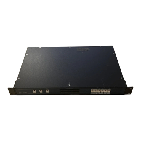
Illumra E3X-232FP User manual

1
Copyright © 2009 ILLUMRA. All rights reserved. Contact ILLUMRA: T: (801) 349-1200 | F: (801) 653-4257 | [email protected] | www.ILLUMRA.com AHD0239B
Figure A: RS-232 (DB-9) Serial Port Pin Signals
Packet Structure
Message Format
Figure B shows the message format. A data block of length n is composed of 2 synchronization bytes, 1
octet for the header and n-1 octets for the message data.
Figure B: Message Format for Asynchronous Serial Communication
Octet Signals and Bit Order
9600 bps; 8 data bits, no parity bit, one start bit, one stop bit
Line idle is binary 1 (standard)
Each character has one start bit (binary 0), 8 information bits (least signicant bit rst) and one stop bit (binary 1)
The signal levels shown in the timing diagram are inverted from the voltages that appear on the RS232 connector.
Figure C: Octet Signals and Bit Order
■
■
■
■
Installation Guide
E3X-232FP
E3X-232FP-WCS
RS-232 Serial Box
Overview
The RS-232 Serial Box is a data interface radio transceiver which can be connected to any system that uses an RS-232 serial port.
The device communicates with ILLUMRA wireless switches, sensors, and receivers and allows other systems to communicate with
ILLUMRA wireless controls.
Compatible Devices
Single Rocker Self-powered Wireless Light Switch; E3T-S1Axx
Dual Rocker Self-powered Wireless Light Switch; E3T-S2Axx
Handheld Self-powered Wireless Light Switch; E3T-S2Hxx
Key Card Access Switch; E3T-C1AWH
SLT Wireless Sensor; E3T-Rxx-2INBP
Self-powered Wireless Occupancy Sensor; E3T-Mxx-SB24
More compatible devices available
Components Included
The following items are included with this product:
A -- (1) ILLUMRA RS-232 Serial Box
Installation
The RF Serial Box can be mounted almost anywhere. The following considerations should be taken into account:
Mount within range of wireless switches and receivers; obstructions limit range (see specications)
Mount in area where power source is available (see specications)
Do not exceed max RS-232 cable length
For optimal range:
-- Do not mount or place RF Serial box close to the oor
-- Do not mount or place RF Serial box inside a metal housing
Connections (Interfacing Protocol)
The RF Serial Box can accept external power through either the power connector, or through pin 9 of the DB9 port. When using
an external power source, connect to the power jack using the provided screw terminals. The power connector accepts 8-28 VAC
or 8-30 VDC. The power connector is polarity insensitive, but power provided through the DB9 port must be DC, not AC, and
connected with correct polarity (+ to Pin 9, - to GND).
A standard DB-9 female connector is provided on the device. It may be necessary to connect the Serial Box to the security/control/
automation panel using a null-modem cable, but connection to a PC requires a standard straight-through cable.
■
■
■
■
■
■
■
■
■
■
■
■

2
Copyright © 2009 ILLUMRA. All rights reserved. Contact ILLUMRA: T: (801) 349-1200 | F: (801) 653-4257 | [email protected] | www.ILLUMRA.com AHD0239B
LENGTH (5 bit) Number of octets following the header octet (11 dec)
ORG (8 bit) Type of telegram (see detail description)
DATA_BYTE 0..3 (8 bit each) Data bytes 0..3 (see detail description)
ID_BYTE 0..3 (8 bit each) 32-bit transmitter ID
STATUS (8 bit) Status eld (see detail description)
CHECKSUM (8 bit) Checksum (Last LSB from addition of all octets except
sync bytes and checksum)
Table C: Detailed Description of ORG Field
ORG eld value
(decimal)
Acronym Description
5 RPS Telegram from a PTM switch module received (e.g. PTM 100 or PTM 200)
6 1BS 1 byte data telegram from a STM sensor module (e.g. STM 250)
7 4BS 4 byte data telegram from a STM sensor module (e.g. STM 100)
8 HRC Telegram from a CTM module received
0-47, 9-255 -- Reserved
Operation
Verify Serial Port – Connect to terminal program, like “HyperTerminal” or “Portmon” and monitor activity on serial port. Each time
another ILLUMRA device transmits, a few copies of the data packet should ow through to the serial port.
The data received from the modules contains non-printable characters. In order to see the exact contents of the received packets, set
up a text capture with Transfer->Capture Text. An alternative to the text capture method is to run a serial port monitoring program
(use Google to search for “portmon” which is available as a free download from microsoft.com, and can display the hexadecimal values
during serial operation).
Save the le in a convenient location.
Serial Data Structure
The structure of the serial data is as follows:
Table A: Serial Data Structure
Bit 7 Bit 0
SYNC_BYTE1 (A5 Hex)
SYNC_BYTE0 (5A Hex)
H_SEQ (3 bits) LENGTH (5 bits)
ORG
DATA_BYTE3
DATA_BYTE2
DATA_BYTE1
DATA_BYTE0
ID_BYTE3
ID_BYTE2
ID_BYTE1
ID_BYTE0
STATUS
CHECKSUM
SYNC_BYTE 0..1 (8 bit each) Synchronization Bytes
H_SEQ (3 bit) Header Identication [refer to table below]
Table B: Header Identication
H_SEQ Meaning Mode
0b 000 Unknown transmitter ID received
(serial telegram only if no ID has been learned so far!)
For RPS also:
-- Known transmitter ID and unknown rocker
-- U-message from known transmitter ID received
For HRC also:
-- Known transmitter ID and unknown rocker
-- Scene switch command (last three bits of ID 0b111) from known
transmitter ID (only rst 29 bits are compared!)
Operating
Mode
0b 001 For 1BS and 4BS: Known transmitter ID received
For RPS: Known transmitter ID and at least 1 known rocker (1 or 2 rockers
operated)
For HRC: Known transmitter ID and known rocker
Operating
Mode
0b 010 New transmitter learned (If a switch telegram is received (RPS or HRC),
the rocker code (RID) is stored together with the ID.)
• Mode 3: a telegram with this header information will be sent also when
in LRN mode a transmitter which is already learned is operated again
Learn Mode
0b 110 Mode 0: Transmitter just deleted (If a switch telegram is received (RPS
or HRC), the rocker code (RID) and module ID are checked. The entry is
only deleted if module ID and rocker are known.)
Learn Mode

Copyright © 2009 ILLUMRA. All rights reserved. Contact ILLUMRA: T: (801) 349-1200 | F: (801) 653-4257 | [email protected] | www.ILLUMRA.com AHD0239B
3
This device or certain aspects thereof is
protected by at least one U.S. or international
patent or has at least one such patent
application pending.
ILLUMRA is a trademark of Ad Hoc
Electronics, LLC. Other trademarks herein are
the property of their respective owners.
Use the hex editor to open the captured text le, and the full packet is visible in hexadecimal format. Note in the packets shown, the
5th byte indicates the state of one of the buttons on the PTM module. Note that the button was pressed for the rst packet, (0x10)
and released for the second packet (0x00). This is the sequence received when a user presses and releases the button on a battery-free
wireless switch.
Specications
Range
Frequency
Power Supply Input Rating
Current
Operating Temperature
Storage Temperature -40
Dimensions
Serial Port Settings 9600 baud, 8 bits, No parity, 1 stop bit
Radio Certication
E3X-232FP
50-150 feet (typical)
315 MHz
8-28 VAC or 8-30 VDC
25mA @ 12 VDC, 15mA @ 24 VDC
-13° to +140°F (-25° to +60°C)
-40° to +140°F (-40° to +60°C)
5.12”W x 3.21”H x 1.10”D
10.7cm x 7.2cm x 2.9cm
9600 baud, 8 bits, No parity, 1 stop bit
FCC (United States): SZV-TCM2XXC
I.C. (Canada): 5713A-TCM2XXC
Contains FCC ID: SZV-TCM2XXC
Contains IC: 5713A-TCM2XXC
The enclosed device complies with Part 15 of the
FCC Rules. Operation is subject to the following two
conditions: (i.) this device may not cause harmful
interference and (ii.) this device must accept any
interference received, including interference that may
cause undesired operation.
Press a switch button and two packets of 14 bytes each will be received and displayed. If a repeater is in range, two copes of each packet
will be received, the later of which will contain a bit indicating that the packet has been repeated.
In order to view the actual contents of the data packet, stop the text capture process by selecting Transfer->Capture Text->Stop. This
step is important, as it closes the le so it can be read by other programs. Now download a hex editor program. A free one called XVI32
is available on the web.
This manual suits for next models
1
Popular Recording Equipment manuals by other brands
Kenton
Kenton MEMORYMOOG User instructions
midiplus
midiplus I61 owner's manual
National Instruments
National Instruments GPIB-232CT-A IBCL EPROM installation guide

KORNEFF
KORNEFF PAWN SHOP COMP 2.0 user manual
Solid State Organ Systems
Solid State Organ Systems Flip user manual
Roland
Roland Boutique JX-03 owner's manual

