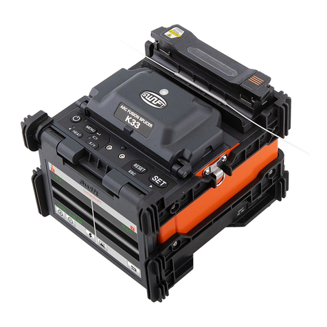
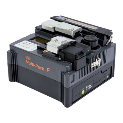
Ilsintech Keyman S1 User manual

1
I . Safety guide
II. Menu Control
1. Pop-up Menu Registration
2. Setting Auto Heat
3. Setting Errors to be Affected or Ignored
4. Menu Clearing the Record of Total Number of Electric Discharge
5. Setting the Amount of Electric Discharge to be Cleared
6. Changing Maintenance Schedule
III. Correction Menu
1. Selecting Correction Menu
2. LED Bright Menu
3. Uart Port
4. ARC Settle
5. Motor Setting
6. Check Up
12
INDEX
2
6
6
7
9
1
9
10
9
7
10
10
11
10
12
10
7
7
8
10
10

2
7. Splice data Update
IV. Maintenance
1. When an Error in Classifying SM and MM in Auto Mode Occurs
2. Eccentricity of Position of ARC Discharge
3. Abnormal Arrangement of Optical Fibers in Connection Operation
4. Occurrence of a Length Difference When Optical Fibers are Initially Placed
5. Occurrence of an Error during Booting
6. In case of High Connection Loss Rate
7. Replacing the Battery
8. Replacing the Mirror
9. Program Upgrade
This specification is applied to the maintenance and management of
released products of which versions are later than Keyman-S1 Version
3.00.
13
10
13
10
12
10
13
10
13
10
13
10
15
10
17
10
17
10
18
10
19
10

3
Keyman S1 has been designed and manufactured for convenient use in indoor
or outdoor working conditions. It is easy and simple to use, but please read
through this manual completely to avoid failures and safety accidents before
you use it. Keyman S1 is designed to easily use, but also contains potential
danger. Therefore, this manual contains all necessary instructions to assure
safe splice.
�Please keep this manual with the product all the time.
Ilsintech(Inc.) is not responsible for equipment damage and personal or
physical damage caused by improper use or modification.
Ⅰ. Safety guide
Warning

4
If an abnormal condition such as the following occurs, immediately turn off
power and disconnect the power source. Next, contact the maintenance
service personnel in Ilsintech(Inc.).
�If unusual smoke, noise or odor or unusual overheating occurs,
�If foreign substance or liquid gets inside the splicer, or
�If the splicer is dropped from a high place or suffers damage
Do not use AC power code other than the allowable power cord indicated.
Doing so may cause a fire, electric shock or injury. Use the power code
provided with S1.
Do not touch the electrodes when S1 is switched on. High voltage and High
temperature from them may cause serious shock or a burn.
Make sure that there is no dust or foreign substance inside the AC plug. Then,
Connect AC power cord to the specified charger and the outlet. Unsafe splice
may cause smoke, fire, equipment damage, serious injury or death.

5
Do not use a voltage other than the allowable power voltage indicated.
AC power supply for the specified charger is AC 100-240V, 50-60Hz.
Please check the AC power supply before using. AC power supply within the
improper range may cause electric shock, equipment damage, serious injury
or even a death. Abnormally high AC output voltage or frequency from the
generator is a common problem. Measure AC output voltage with a circuit
tester before connecting AC power cord. Regular inspection is needed
because improper high voltage or frequency from the generator may cause
serious injury, electric shock, equipment damage or death.
Do not severely pull, heat or modify the provided AC power cord. The use of
damaged power cord may cause hazardous conditions such as fire or injury.
Connect only to 3-core AC power cord. Do not connect to 2-core power cord,
cable or plug.
To reduce the risk of electric shock, do not touch the AC plug, the AC power
Warning

6
code and the splicer with wet hands.
Do not disassemble AC adapter, battery or the splicer. Any modification to
the splicer may cause a fire, electric shock or injury.
When you use external battery, see the following instructions.
�The use of improper external battery may cause smoke, equipment
damage, or in serious cases burning, injury or death.
�Do not throw the battery into a fire or a garbage dump.
�Do not charge the battery close to flames.
�Do not give severe vibration or shock to the battery.
�If the battery is not fully charged within 6 hours or green LED
lamp is not on, immediately stop charging and contact Ilsintech(Inc.)
Do not place any object on AC adapter during charging.
Only use the specified battery charger(S-1B) and the specified battery pack(S-
1B). The use of any battery pack other than the specified one may cause
smoke or fire, equipment damage, injury or death.

7
Only use the specified battery charger(S-11).
Do not use AC power other than the allowable power indicated.
Do not let battery(S-1B) or the terminal of the specified charger be short-
circuited. Excessive current flow may cause damage to the equipment and
persons.
Avoid the use of S1 in a hazardous location in which harmful gas or
flammable gas can generate. In such conditions, the electrical arc of the
fusion splicer can result in bursting or fire.
Do not use compressed gas to clean S1.
If you carry the transport case connected with a belt, first check the belt is
strong enough. The worn belt may fail to sustain the case, resulting in
Warning

8
equipment loss or injury.
Wear safety glasses for protection from glass fibers. Glass fibers may cause
serious damage to eyes or skin tissue.
Do not use the splicer in high temperature conditions. Doing so may cause
equipment loss or injury.
Do not use a splicer in high temperature conditions. Doing so may cause
equipment loss or injury.
Caution

9
During or after heating protection sleeves in the tube heater, do not touch both
parts. Injury from high temperature could occur.
Do not place S1 in unstable locations. If the equipment is dropped, injury or
equipment damage could occur.
S1 is a precision instrument. It should be handled with care and precision.
When transporting it, use its specified transport case to protect it from dust,
dust, moisture, shock and impact.
Replace the electrodes the right way.
�Only use the specified electrodes.
�Place the new electrode in the right position.
�Replace the electrodes in pairs.
Not doing so may cause abnormal arc and equipment damage or deterioration
in splice performance.
Only use ethyl alcohol (more than 96 %) to clean the splicer including object

10
lenses, V-grooves, wind-proof glass, LCD monitor, and the main body.
To prevent modification, discoloration and low performance, do not use any
kind of chemicals.
Do not use lubricants including oil and grease for S1. Doing so may cause
performance deterioration and equipment damage.
Do not store the equipment in high-temperature or high-humidity conditions.
Equipment damage could occur.
Qualified experts should check up technical matters concerning S1. Not doing
so may cause fire or electric shock. Please contact qualified service personnel
in Ilsintech(Inc.) and get A/S service.
1. Pop-up Menu Registration
Ⅱ. Menu Control

11
⇒To activate a mode, select the mode by
moving the cursor and then push key.
Push Esc to return to previous menu.
Both Connection Mode and Heater Mode can be registered in Pop-up menu,
which allows user to select each mode in a quick manner by pushing either up
or down direction key.
Push or
Registering each mode
Connection Mode Registration
Push Menu Key →Select Connection Mode →Move to the mode to
be registered →
Push Set Key →Pop-up menu registration box appears →Assign a
number to be used by moving up and down direction keys →Push →
Completion of the registration
Heater Mode Registration
Push Menu Key →Select Heater Mode →Move to the mode to be
registered →Push Set Key →Pop-up menu registration box appears →
Assign a number to be used by moving up and down direction keys →Push
→Completion of the registration
1
2
2
2

12
2. Setting Auto Heat
The function of setting auto heat is useful, especially, in performing consecutive
connection works. When the wind protection cover is opened after completing a
connection, the heater starts to be operating and stops at the end of pre-set time
period.
Menu Key →Main Menu →Select additional function of connection →Select
basic →Set to On or Off in Auto heat
3. Setting Errors to be Affected or Ignored
Errors not affecting the operative function of connection can be either ignored or
selected.
Menu Key →Main Menu →Select additional function of connection →Ignore
connection errors →Set On or Off for each item
4. Menu Clearing the Record of Total Number of Electric Discharge
The total number of electric discharge can be
initialized.

13
Menu Key →Aux →Select CLEAR ARC COUNT, in which push, simultaneously,
both X, Y Key and Key.
The total number of electric discharge becomes 0 when selecting Initialize and
pushing Enter key.
5. Setting the Amount of Electric Discharge to be Cleared
The electric discharge amount to be cleared can be
set.
Menu Key →Main→Select Splice Option, in which
push, simultaneously, both keys of X, Y and
.
The amount of electric discharge to be cleared can
be re-set.
6. Changing Maintenance Schedule.
Menu Key →Other→Select Maintenance, in
which push, simultaneously, both X, Y Key and
Key. Change the date.

14
1. Selecting Correction Menu
Push Menu Key →SUB →OTHER →Select
System Setting →in which screen, push,
simultaneously, both X, Y Key and Key.
2. 2. LED Bright Menu
This menu is used for adjusting the brightness of camera flashes. A sub menu
appears when selecting this menu.
LED Bright
After adjusting the brightness of flashes by selecting the
menu for adjusting the brightness of camera flashes,
Ⅲ. Correction Menu

15
select Menu Key →OTHER →LED CHECK, in which keep the brightness value
between 80~86.
LED Bright (Auto)
This is an automatically adjusted brightness value of LED
flashes which is applied when the device is booted. The
standard value has been set to 83.
2. 3. Uart Port
Check if it has been set to Data Download when performing Program Up-Grade.
2. 4. ARC Settle
ARC Position
Menu used for correcting the centers of arranged optical
fibers and ARC

16
Limittion Re-arc times
Menu for setting re-arc discharge times
The number set is the maximum times allowing re-arc discharge.

17
2. 5. Motor Setting
Menu for setting measuring values of camera
motor and X, Y motor
The initial setting value of each motor shall be
recorded prior to Up-Grade.
A screen as next figure appears upon selecting the
menu.
Core Equalization
Menu for correcting images from the camera
Auto Mode: Menu for setting the reference position of the camera in Auto
Mode (Do not change the initially set value)
Except Auto: Menu for correcting the size of optic fibers’core when
conducting ALIGNMENT (Do not change the initially set value)
Loss Calculation equalize: The control value of camera, which is to be
applied in calculating Loss (Do not change the initially set value)
Fiber Type Menu
1
2
3

18
Menu for correcting image data of optical fibers in Auto Mode
Fiber Type Resister: Menu for setting a standard value for recognizing
Fibers in Auto Mode (Do not change the initially set value). The value is
automatically adjusted when correcting the motor.
Fiber Type Limit: Menu for setting a threshold value for recognizing Fibers in
Auto mode (Do not change the initially set value).
Fiber Total Limit: Menu for setting a threshold value of Fiber data (Do not
change the initially set value).
First-Time Compensation: Menu for setting an automatic correction value in
Auto Mode (Do not change the initially set value).
Temp Compensation
Menu for setting temperature compensation (Do not change the initially set value).
X, Y Motor Offset
Menu for setting a compensation value when a length difference occurs upon placing
right and left fibers
2. 6. Check Up
Motor Setting: A screen which shows the reference line when adjusting the
position of optical fibers (, which are used in replacing a lens or camera)
1
1
2
3
4
1

19
Fiber Shape Set 1: A standard value used for judging the faulty status of a cut
section of optical fibers (Clad Section). The bigger the size of this value is, the
less sensitive the fault detection capability becomes.
1Fiber Shape Set 2: A standard value used for judging the faulty status of a
cut section of optical fibers’core. The bigger the size of this value is, the less
sensitive the fault detection capability becomes.
Fiber Shape Set 3: A standard value used for judging the broken status of
optical fibers. The smaller the size of this value is, the less sensitive the
function becomes.
7. Splice Data Update
Used in conducting Splice Mode and Heater Mode Update.
※Upon performing Splice Mode and Heater Mode, all existing data is initialized. Extra
caution is required.
2
3
4
Ⅳ. Maintenance
Other manuals for Keyman S1
2
Table of contents
Other Ilsintech Welding System manuals
Popular Welding System manuals by other brands

Blue point
Blue point MIG 115 operating instructions

Clarke
Clarke WE6480 MIG 95 operating & maintenance manual

Victor
Victor 42 CUTMASTER Service manual

Lincoln Electric
Lincoln Electric RANGER IM742-A Operator's manual

SUNSTONE
SUNSTONE PicoDC user guide

EWM
EWM Tetrix 230 AC/DC Comfort 8P TM operating instructions