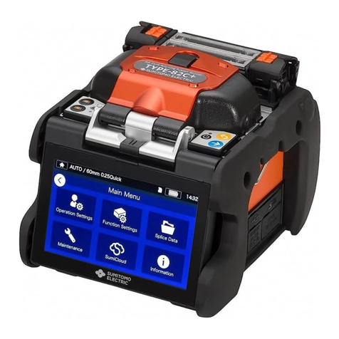
Ilsintech Keyman S1 User manual

Instruction manual
Optical fiber fusion splicer
Keyman S1
Please read through this manual completely
before its first use.

1
I. Safety guide
II. Product structure
1. Parts of the splicer
2. Requirements for splicing
III. Product guide
1. Outward of the main body
2. Parts for fusion splicing
IV. Using method
1. Power supply
V. Instructions for use
1. Function keys
2. Turning on S1
4. Cleaning optical fibers
5. Inserting optical fibers into protection sleeves
6. Cleaning and stripping optical fibers
7. Cleaving bare optical fibers
8. Placing the fiber in the splicer
9. Splicing procedures
10. Removing spliced optical fibers
11. Installing the protection sleeve in the sleeve heater
12. Heating the protection sleeve
VI. The maintenance of quality splice
1. Cleaning and inspection before splicing
2. Regular inspection and cleaning
VII. Main Menu
1. Select Splice Mode
3. Installing the protection sleeve lauder
Contents
4
8
8
9
10
1
12
13
13
17
17
18
29
19
20
20
20
21
22
27
27
28
29
31
34
10
34
19

2
2. Select Heater Mode
3. Arc calibration
5. Splice Memory
VIII. Sub Menu
1. Language
2. Power Save
3. Menu Lock
4. Other Option
IX. Auxiliary menu
1. Replace Electrodes
2. Stabilize Electrodes
3. Clear Arc Count
4. Set Calendar
X. Error messages
1. FIBER DIRTY
2. REPLACE POSITION
3. TOO LONG FIBER
5. LOSS LIMIT OVER
6. FIBER THIN ERROR
7. FIBER THICK ERROR
8. CORE BUBBLE
XI. Solutions to splicing problems
1. High loss Limit
2. Abnormal splice operation
Ⅻ. Other menus
1. Diagnostic test
2. Dust Check
3. Motor Drive
53
53
54
55
58
60
65
65
65
65
66
66
66
67
68
68
69
70
70
71
44
47
50
60 60
62
63
63
70
4. Splice Option 49
5. Sensor value 64
4. FIBER OVER ANGLE 66

3
4. Maintenance information
Ⅼ. Q & A
1. Power supply
3. Tube heater operation
4. Management
5. Other settings
Ⅽ. PC Program set up
1. PC Program set up
Ⅾ. Warranty period and contact address
1. Warranty period and limitation
2. Before you present the splicer for warranty service
3. Information required for repair service
4. Splicer transportation
5. Repair
Warranty
72
73
73
76
76
77
84
84
84
84
85
78
78
2. Splice operation 74
85

4
Keyman S1 has been designed and manufactured for convenient use in indoor or
outdoor working conditions. It is easy and simple to use, but please read through
this manual completely to avoid failures and safety accidents before you use it.
Keyman S1 is designed to easily use, but also contains potential danger. Therefore,
this manual contains all necessary instructions to assure safe splice.
Ilsintech(Inc.) is not responsible for equipment damage and personal or
physical damage caused by improper use or modification.
If an abnormal condition such as the following occurs, immediately turn off
power and disconnect the power source. Next, contact the maintenance service
personnel in Ilsintech(Inc.).
If unusual smoke, noise or odor or unusual overheating occurs,
If foreign substance or liquid gets inside the splicer, or
If the splicer is dropped from a high place or suffers damage
Do not use AC power code other than the allowable power cord indicated.
Doing so may cause a fire, electric shock or injury. Use the power code
provided with S1.
Do not touch the electrodes when S1 is switched on. High voltage and High
Make sure that there is no dust or foreign substance inside the AC plug. Then,
Connect AC power cord to the specified charger and the outlet. Unsafe splice may
cause smoke, fire, equipment damage, serious injury or death.
Ⅰ. Safety guide
Please keep this manual with the product all the time.
Warning
temperature from them may cause serious shock or a burn.

Do not use a voltage other than the allowable power voltage indicated.
AC power supply for the specified charger is AC 100-240V, 50-60Hz.
improper range may cause electric shock, equipment damage, serious injury or
even a death. Abnormally high AC output voltage or frequency from the generator
is a common problem. Measure AC output voltage with a circuit tester before
connecting AC power cord. Regular inspection is needed because improper high
voltage or frequency from the generator may cause serious injury, electric shock,
equipment damage or death.
Do not severely pull, heat or modify the provided AC power cord. The use of
damaged power cord may cause hazardous conditions such as fire or injury.
cable or plug.
To reduce the risk of electric shock, do not touch the AC plug, the AC power code
and the splicer with wet hands.
Do not disassemble AC adapter, battery or the splicer. Any modification to the
splicer may cause a fire, electric shock or injury.
When you use external battery, see the following instructions.
The use of improper external battery may cause smoke, equipment
damage, or in serious cases burning, injury or death.
Do not throw the battery into a fire or a garbage dump.
Do not charge the battery close to flames.
Do not give severe vibration or shock to the battery.
If the battery is not fully charged within 6 hours or green LED lamp
Do not place any object on AC adapter during charging.
Only use the specified battery charger(S-1B) and the specified battery pack(S-1B).
The use of any battery pack other than the specified one may cause smoke or fire,
equipment damage, injury or death.
Warning
Please check the AC power supply before using. AC power supply within the
Connect only to 3-core AC power cord. Do not connect to 2-core power cord,
is not on, immediately stop charging and contact Ilsintech(Inc.)
5

Warning
Only use the specified battery charger(S-11).
Do not use AC power other than the allowable power indicated.
Do not let battery(S-1B) or the terminal of the specified charger be short-
circuited. Excessive current flow may cause damage to the equipment and
persons.
Avoid the use of S1 in a hazardous location in which harmful gas or flammable
gas can generate. In such conditions, the electrical arc of the fusion splicer can
result in bursting or fire.
Do not use compressed gas to clean S1.
If you carry the transport case connected with a belt, first check the belt is
strong enough. The worn belt may fail to sustain the case, resulting in equipment
loss or injury.
Wear safety glasses for protection from glass fibers. Glass fibers may cause serious
damage to eyes or skin tissue.
Do not use the splicer in high temperature conditions. Doing so may cause
equipment loss or injury.
Do not use a splicer in high temperature conditions. Doing so may cause
equipment loss or injury.
6

During or after heating protection sleeves in the tube heater, do not touch both
parts. Injury from high temperature could occur.
Do not place S1 in unstable locations. If the equipment is dropped, injury or
equipment damage could occur.
S1 is a precision instrument. It should be handled with care and precision. When
transporting it, use its specified transport case to protect it from dust, dust,
moisture, shock and impact.
Replace the electrodes the right way.
Only use the specified electrodes.
Place the new electrode in the right position.
Replace the electrodes in pairs.
Not doing so may cause abnormal arc and equipment damage or deterioration in
splice performance.
Only use ethyl alcohol (more than 96 %) to clean the splicer including object
lenses, V-grooves, wind-proof glass, LCD monitor, and the main body.
To prevent modification, discoloration and low performance, do not use any kind
of chemicals.
Do not use lubricants including oil and grease for S1. Doing so may cause
performance deterioration and equipment damage.
Do not store the equipment in high-temperature or high-humidity conditions.
Equipment damage could occur.
Qualified experts should check up technical matters concerning S1. Not doing so
may cause fire or electric shock. Please contact qualified service personnel in
Ilsintech(Inc.) and get A/S service.
Caution
7

8
1. Parts of the splicer
Other accessory items
- Carrying case
- Instruction manual
Ⅱ. Product Structure
S1 main unit S-1B battery pack
AC cord S-11 battery charger

2. Requirements for splicing
Fiber type 0.25mm 0.9mm
Basic sleeves
9
length 40mm length 60mm
Optical fiber
protection
sleeves
Micro sleeves
length 45mm
length 20mm
length 25mm
length 34mm
Optical fiber
stripping
tools
Coating stripper
Optical fiber cleaver [CI-03]
Optical fiber
cleaving tools
Optical fiber holder [standard]
)
cleave length : 16mm (fixed)
cleave length : 5 ~ 20mm(variable
Optical fiber holder [FTTH]
cleave length : 10mm (fixed)
length : 5 ~
(variable)
cleave
20mm
Optical fiber
cleaning tools
Use cotton or gauze pad and alcohol dispenser.
Ethyl alcohol (purity > 96%)

1. Outward of the main body
Ⅲ. Product guide
Keyman S1 is an optical fiber fusion splicer, designed to connect various optica
fibers using DCA technology. S1 is a light, small and convenient device with lo
l
w
splice loss and fast splice speed suitable for both indoor and outdoor workin
g
fconditions. Please read all the instructions in this manual to make the best use o
S1.
10
Wind protector
ual handle
Switch panel
Monitor
Sleeve heater
Sleeve loader
D

PC connection
jack (USB 2.0)
Connection jack for
external monitor (RCA
jack)
Connection jack for the
specified charger
Connection jack for
external DC power and
back-up battery.
11
Power switch
r keCurso
y
Power indicator
keMenu
y
Esc ke
y
Enter ke
y
Switch for built-in battery
remaining capacity indicator
Screen
conversion
Key Key to execute
splicing
Key to
execute arc
Heater 2 key (low heater)
eater1 movement lamH
p
Heater 1 key (top heater)
Reset, key for
return
Heater 2 movement lamp
Built-in battery remaining
capacity indicator

12
icing
2. Parts for fusion spl
Lower electrode
cover
Illumination for
night work
Groove to install
sleeve lauder
X-axle camera
Lower electrode
Fixed right
fiber cover
To
Groove to install
sleeve lauder
p
electrode
Top electrode
cover
Camera illumination
Y-axle camera
ver Fixed left fiber co
Y reflector
-BLOCK Lever
V-BLOCK R
flector
V-BL
Wind protector
V
X re
OCK L
Heater 2
Center heater
Heater
Cover close lever
Heater cover
Sleeve lauder
1

13
Charging the battery
.
1. Power supply
The highly efficient built-in battery of S1 enables to use SI without attaching
additional battery.
Ⅳ. Using method
If the specified charger is connected to
“Charger” Jack on the left to the main unit and
the AC cord to AC outlet, the charging LED
lights up red, green and yellow in sequence and
charging starts when the LED lights up red
after about 0.5 second. The LED light turns
green when charging is completed. (After this
the chargin
g
should be continued for about 30
minutes.)
S1 adopted the floating charge system.
Power indicator LED
The LED light turns red→green→yellow
→off→red when minimum AC power is
on.

14
AC operation
The charging LED light blinks red → green → yellow in sequence.
The LED lights up red again when the charge i
supply is done. You may use the product.
s completed and normal power
DC operation with an external battery
Do not use a battery charger other th
provided with the product. Doing s
conditions such as fire.
an the specified charger
o may cause hazardous
When yellow LED blinks, disconnect the AC cord and connect
it again after ten minutes.
Protective devices are built in the battery of S1(S-1B) and so
prevent over arc, over charge and overload. When these
protection functions are performed, its power is automatically
shut off. In this case, after ten seconds, connect the DC plug of
the charger to “charger” jack on the left to S1 and then connect
AC cord to the power outlet. And so, the shut-off will be canceled
and charging begins.
Connect the DC plug of the AC specified
charger to “charger” jack on the left to S1.
When normal AC voltage is supplied, the
green light of the AC adapter turns on.
Please use only the normal power and make
sure more than 250V is not supplied.
Connect the AC power cord of the charger to
the AC outlet supplied with normal power.
Connect 12V car cigar-jack to “DC IN” jack
on the left to S1 main unit. Only use the
specified cord.

15
Battery capacity check
Large-capacity battery(S-SB) use
Built-in battery use
Battery remaining capacity can b part of the screen when
the product is in use.
e displayed on the right upper
At this time, charging does not work.
Only use the specified voltage. (DC 12V car cigar-jack) Do not
simultaneously use the cigar-jack for the splicer and other
products. The car battery could be overpowered.
Have an optional large capacity battery(S-SB) installed on the lower part of S1 and
connect the connection cord to “DC IN 12V” jack on the left part of S1.
Please make sure that there is more than 20% battery capacity for even a few
connections.

16
Charging the battery
Battery remaining
capacity display
(Monitor)
Remaining capacity indicator (LED) remaining
capacity
(5 bars) 5 LED 80 ~ 100%
(4 bars) 4 LED 60 ~ 80%
(3 bars) 3 LED 40 ~ 60%
(2 bars) 2 LED 20~40%
1 LED 10%
(1 bar)
(no bar) 1LED blinks
Within 5 %
(Immediate charge
is needed)
Connect DC cord of specified charger S-11 to “CHARGER” jack on the left part of
large-capacity battery. Connect AC cord to the outlet with the appropriate AC
voltage. The charging LED light blinks red → green → yellow in sequence and the
LED lights up red again, which means charging has begun. It takes approximately 3
hours for the built-in battery and 6 hours for the large-capacity battery to be
completely charged. Keep charging for buffing for about 30 minutes after the green
light is turned on.
Connect DC cord first and then AC cord to the battery at all
times.

1. Function keys
17
Ⅴ. Instructions for use
This i
moni
press
s Power ON and OFF key. If you press the key, power is on, the
tor is turned on and next square indicator lights up red. If you
it for about one second again, the lamp turns off and power
turns off.
is a key to move the cursor leftward. If you press this key on the
home screen, the screen becomes dark. This key also controls the
movement of optical fibers and camera focus in the passive mode. (For
more details, refer to the passive mode menu.)
his is a key to move the cursor rightward. If you press this key on
the home screen, the screen becomes bright. This key also controls
the movement of optical fibers and camera focus in the passive mode.
(For more details, refer to the passive mode menu.) If you press the
key when s displayed on the right part of the menu screen, the
submenu is activated.
is a key to move the cursor upward.
key is used to select a motor in the passive mode.
(For more details, refer to the passive mode menu.)
is a key to move the cursor downward.
key is used to select a motor in the passive mode.
(For more details, refer to the passive mode menu.)
This is a key to go to the menu screen
This
T
i
This
This
This
This
This key is used to cancel your selection or to return to the previous
screen.
This Enter key is used to complete Edit setting or go to the next step on
the menu.
This key is to shut off power when the splicer is stopped by abnormal
voltage or external shock.

18
2. Turning on S1
Monitor OPEN
Monitor angle
Monitor ON
Battery remaining capacity display key.
If you press this key one time, battery remaining capacity LED lights up
and then off one second later.
This command key is to execute splicing.
Next movement in the case of section operation
This key is used to cancel splicing or initialize the splice function.
This key is to convert the splicing screen. Each push converts the
screen to X, Y and both X and Y screen.
This key is to execute arc in the passive splice or section movement
splice. It is also used to execute additional arc.
This key operates the upper sleeve heater.
When it is turned on, the left indicator lights up red.
If you press the key once again, the heater turns off.
This key operates the lower sleeve heater.
Lightly hold the monitor center and lift it up
as in picture.
The monitor viewing angle is adjustable for
the convenience of the user.
Press the POWER key about 0.5 second with the
wind protector closed.
Home screen is displayed when all motors are
reset to their initial positions.

Home screen
19
Monitor brightness
Splice mode
Heater mode
3. Installing the protection sleeve lauder
4. Cleaning optical fibers
Set a value with leftward or rightward cursor
key and press the ENTER key to change
Monitor brightness.
Select a proper splice mode for exact splicing.
The current splice mode is displayed on the
home screen.
Press MENU key on the home screen
to change the splice mode.
The splice mode and heater mode are
displayed on the main menu screen.
Select a proper heater mode to heat
protection sleeves. The current heater mode
is displayed on the home screen.
LCD brightness adjustment
Setting
Get out the protection sleeve lauder on the
right to the wind protector and insert it into
the left or right groove.
Clean the optical fiber with soft cloth or cotton moistened with alcohol. Dust in a
protective sleeve may cause cut-off or attenuation.
Other manuals for Keyman S1
2
Table of contents
Other Ilsintech Welding System manuals
