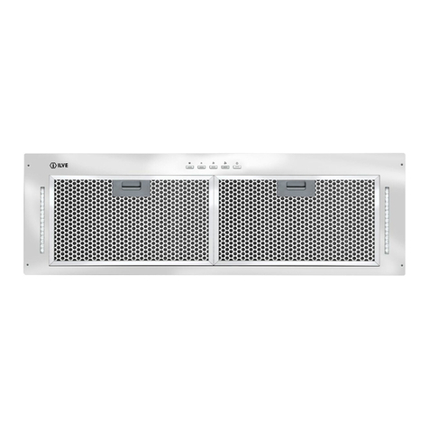
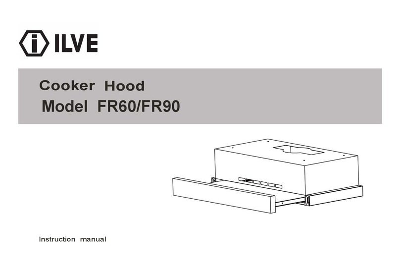
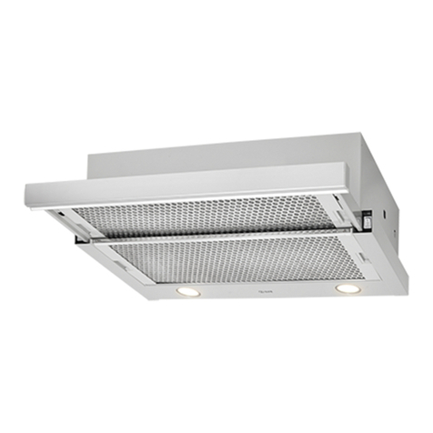
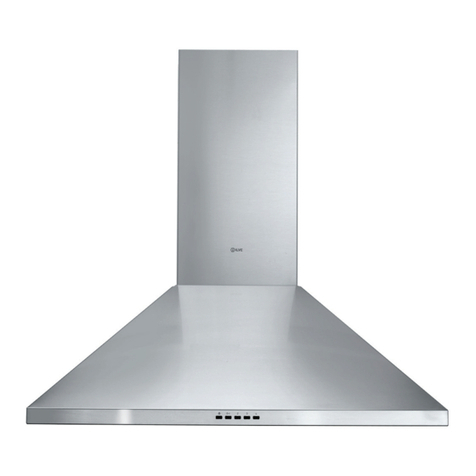
ILVE VAPORE/60 User manual

VAPORE/60
VAPORE/90
230Vac - 50Hz


Exhausting cooker hood. The equipment is constructed in
accordance with European Standards and with the requirements
included in the following Directives: 2006/95EC ( Low Voltage
Directive), 2004/108 (Electromagnetic Compatibility).
1 INSTALLATION
Read the whole instruction booklet before installing and/or using
the hood.
With the hood correctly installed, the minimum distance between
the wall-mounted unit and the cooking surface of a gas stove
must be at least 62 cm.
With the hood correctly installed, the minimum distance between
the wall-mounted unit and the cooking surface of an induction
cooker must be at least 50 cm.
Please comply with all the regulations regarding air discharge.
The air must never be discharged into a duct used to discharge
the fumes produced by gas combustion appliances (not
applicable to hoods used in ltering mode).
The room must have sufcient ventilation when the hood is used
together with other appliances that use gas or other fuel.
During installation, we recommend you move the units
underneath it for better accessibility.
The hood is supplied with all the xings required to install it,
suitable for most wall units. Check anyway that the surface of the
wall units is adequate.
Installation must be carried out by competent and qualied
installers in compliance with the regulations in force.
The hood is provided with a plastic back spacer to adapt its depth
to that of the wall unit (from 30 to 35 cm). Proceed measuring the
depth of the wall unit side “X” (Fig. 1), deduct from this value the
depth of the hood that is 30cm. The difference is depth “A” (Fig.
1), the distance the spacer will have to be cut at with a cutter. If
the wall unit depth is 30 cm, no spacer is required.
At this point, x the already cut spacer to the hood (Fig. 2).
Fix the two brackets supplied to the unit internal walls, complying
with the distances shown (Fig. 3).
Insert the hood from the front; use the previously xed brackets
as guides that must be inside the seat located on the hood sides
(Fig. 4).
After positioning the hood correctly, x it to the guides with the 4
screws supplied (Fig. 5).
2 ELECTRICAL CONNECTIONS
This appliance must be connected to an earthed system.
Two types of connection to the network are possible:
With a standard plug connected to the mains cable and
inserted in an accessible system socket (that can be
disconnected during maintenance). Ensure the plug is
accessible also once the installation is completed.
Via a xed connection to the mains, placing in-between a
bipolar switch ensuring disconnection from the mains, with
a distance in the contact opening that allows complete
disconnection from the mains in the conditions of
overvoltage category III, in compliance with the installation
regulations. The earth connection (yellow-green wire)
must not be interrupted.
For voltages and frequency, check the data plate inside
the appliance.
If the power cable is damaged, it must be replaced by the
manufacturer or by its technical service centre or, anyway,
by a qualied person, in order to prevent any risk.
3 USE
This hood can be used in extracting or ltering mode.
Extracting (expulsion to the outside). Kitchen fumes are
expelled through the piping (not supplied with the hood)
connected to the motor discharge.
The piping must never be connected to combustion discharge
pipes (stoves, boilers, burners, etc.).
The use of long pipes, with many bends, corrugated and with a
diameter smaller than the motor outlet’s will cause a decrease in
extracting performance and an increase in noise.
Filtering (recycling). The fumes pass through the carbon
anti-odour lter (not supplied with the hood) to be puried and
recycled in the kitchen. The use of the carbon anti-odour lter
reduces the hood performance, we therefore recommend the
hood is installed in extracting mode.
4 OPERATION
This hood has been designed to prevent the formation
of condensation on its lower surfaces when it is installed
over an induction cooker.
Unlike a gas stove, an induction cooker heats only the
pans containing the food and not the surrounding area, so
the surfaces of the hood remain cold.
When the hot cooking fumes go up, they hit the hood cold
surfaces, condense and therefore release the humidity in
the air that quickly transforms into small water drops that
inevitably fall on the cooking surface and food, carrying
with them fat and impurities.
To prevent this from happening, all the lower surfaces of
the hood are heated by a system of internal and therefore
invisible resistors, so the hood lower surfaces getting
warm, even without switching the cooker on, is quite
normal and does not show that the product is not working
properly.
To switch the hood on, rst open the fume ap using the
relative handle in the lower part. Lightly pull downwards
and then extract ap “A” fully (Fig. 6). A special sensor will
automatically switch the hood off when you try and close
the ap with the hood on.
The controls consist of keys to switch the TL lamp on, to
switch speed one on and switch extractor T1 off, to select
the T2-T3-T4 running speeds and to activate the anti-
condensation function T5 (Fig. 7). The anti-condensation
function comes automatically on when the hood is switched
on with key T1, it can anyway be switched on and off with
key T5.
To switch the motor off, press T1 only once if the hood is
operating in 1st speed, twice if it is running at other speeds.
The internal fat lter is not heated to allow condensating
most of the humidity in the air, this surface will therefore
show some drops that are collected in a special tray.
This container should be emptied every time you nish
cooking. To empty the container, rst of all open fume ap
“A” (Fig. 6), with the hood switched off, pull lever “B” (Fig.
8), located in the back of condensate tray “C” downwards
INSTALLATION, OPERATING AND MAINTENANCE INSTRUCTIONS FOR COOKER HOOD H15 MODELS
230-240 Vac - 50 Hz

(Fig. 8) and at the same time position a container under
drain valve “D” (Fig. 8) present in the lower part of the
same tray. The collected water and impurities will drain
from this valve.
The hood should be switched on a few minutes before
starting cooking to allow the lower parts to warm up and
left on until all odours have disappeared.
While cooking, keep the hood maximum extracting speed
on to get the best possible performance in terms of both
extraction and reduction in surface condensation.
ACTIVATION OF ADJUSTABLE DELAYED AUTO-OFF
FUNCTION
With the hood in operation, select the desired speed, press
without releasing the key of the speed corresponding to
the auto-off minutes you wish to set, until it starts ashing,
keeping in mind that:
T1 equals 5 minutes
T2 equals 10 minutes
T3 equals 15 minutes
The set speed can be modied during the auto-off time.
FILTER MAINTENANCE WARNING
Grease lter
Every 30 hours’ operation, when the hood is switched off,
all the LEDs of the speed keys light up continuously for 30
seconds to warn the grease lter “E” needs to be cleaned
(Fig. 9). To zero the timer, keep the T1 key pressed with
the extractor OFF, otherwise the device will give the same
warning the next time the hood is switched off.
Carbon anti-odour lter (optional)
Every 120 hours’ operation, when the hood is switched off,
all the LEDs of the speed keys light up continuously for
30 seconds to warn the carbon anti-odour lter “F” needs
replacing (Fig. 9). To zero the timer, keep the T1 key
pressed with the extractor OFF, otherwise the device will
give the same warning the next time the hood is switched
off.
FULL CONDENSATE CONTAINER WARNING
An electronic internal sensor immediately switches the
hood off and the speed LEDs on when the water in the
condensate collection tray reaches the maximum level.
To zero the warning and switch the hood back on, the
condensate collection tray needs to be emptied.
5 MAINTENANCE AND REMINDERS
Before any maintenance or cleaning, disconnect the hood
from the mains and check there are no pans on the cooking
surface.
Pay careful attention to the fat lter, which is used to
withhold the fat particles contained in the steam. The fat
lter must be washed when the relative warning is displayed
or at least once a month in warm water and detergent (in the
dishwasher too). After a few washes the lter may discolour.
This is normal and does not mean that it must be replaced.
For any maintenance, the fat lter must be removed from
the hood. First of all open the fume ap of the hood using
the appropriate handle located in the lower part, to do this
slightly pull downwards and then extract ap “A” fully (Fig.
6). With the hood switched off, open the condensate tray
“G” (Fig. 11) pulling from the back “I” (Fig. 12). The tray will
lower slightly and rotate on itself at the front “L” (Fig. 12) to
nally come down.
You will then access the internal fat lter and be able to take
it out with the relative handle “H” (Fig. 11).
At this point you can proceed and clean the lter.
To reinstall the fat lter, repeat the instructions in reverse
order.
The function of the carbon anti-odour lter, if any, is to
capture the odours in the cooking fumes. The air is puried
and released back into the room. The anti-odour lter must
not be washed but must be replaced when the relative
warning is displayed or at least 3-4 times a year. Ask the
Manufacturer for lters.
To replace the carbon anti-odour lter, rst of all open the
fume ap of the hood using the appropriate handle located
in the lower part, to do this slightly pull downwards and then
extract ap “A” fully (Fig. 6). With the hood switched off,
open the condensate tray pulling it from the back “I” (Fig.
12). The tray will lower slightly and rotate on itself at the
front “L” (Fig. 12) to nally come down.
You will then access the internal fat lter and be able to take
it out with the relative handle “H” (Fig. 11).
The carbon lter is located above the fat lter. To replace
the carbon anti-odour lter, slide the steel frame containing
it towards the back (Fig. 10). Once the frame has been
extracted, the carbon anti-odour lter inside it can be
removed and replaced.
To reinstall the new carbon anti-odour lter, repeat the
operations in reverse order.
The hood must be cleaned immediately after installation and
the removal of the protective lm in order to eliminate any
glue residues and other potential impurities.
The hood must be cleaned regularly and carefully, both
inside and out (at least once a month).
Do not allow dirt to accumulate on the external and internal
surfaces of the hood.
Do not use acid or base products or abrasive sponges to
clean the external frame.
Clean the hood with a sponge dampened with warm water
and a small quantity of neutral detergent (e.g. washing-up
liquid) to eliminate any traces of fat that may have deposited
on it.
Rinse with a damp cloth, removing all detergent carefully,
following the direction of the satin nish of the steel surface.
Drying, above all in the areas where water is very hard and
leaves scale deposits, is particularly important.
The hood is tted with a LED lamp that, apart from
guaranteeing good lighting and considerable power savings,
ensures an average life 10 times longer than traditional
lamps. If it must be replaced, contact the service centre.
6 WARNINGS
The present instruction manual is an integral part of the appliance
itself, therefore it must be carefully kept and ALWAYS accompany
it, even in case of its assignment to another owner or user or in
case the cooker hood is moved to another installation plant.
Any eventual adjustment to the electrical system, which may be
necessary to install the cooker hood, must be carried out only
by competent people. Any repair carried out by no competent
people may cause damages. For any repair or needed technical
action make reference to a Technical Assistance Center, which is
T5 T1 T2 T3 T4 TL
7

authorized to carry out the replacement of the spare parts.
Always make sure that all the electrical parts (lights, exhaustion
unit) are disconnected when the appliance is not in use.
By storms take off the main switch of the house electrical system.
The using of the cooker hood must not be other than the use of
exhausting units for cooking damps on domestic kitchens. The
manufacturer does not accept any liability for damages caused
by people, animals or things, by installation and maintenance
mistakes or by any illegitimate use.
Make sure that the voltage (V) and the frequency (Hz) ratings
indicated on the plate inside the cooker hood correspond to the
ones available in the installation place.
We remind that the use of products functioning with electrical
energy implies the observance of some essential security rules,
as follows:
• This equipment is not intended for people (children
included) with reduced mental or motor capacities, with lack
of experience or knowledge, unless they are supervised or
unless a person responsible for their security, gives them
instructions regarding the use of the equipment. Children
must be supervised in order to be sure that they do not play
with the equipment.
• Any cleaning action is forbidden if the appliance hasn’t been
disconnected from the main power supply and if the main
switch of the house electrical system is not off. If cleaning
is not carried out according to these instructions, a re may
break out.
• Do not pull, take off or twist the cable coming out from the
appliance, even though this has been disconnected from the
main power supply.
• Do not sprinkle or throw any water directly on the appliance.
• Do not stick any sharp tool inside the exhausting holes and
into the air discharge.
• Do not take out the lters in order to reach the internal
sides of the appliance in case the main switch of the house
electrical system is not off.
• Do not singe or ambé directly underneath the cooker hood.
Take particular care when frying to ensure that the oil does
not catch re.
3 4
30
X
A
A=X-30
A
1 2

9
11
12
8
5 6
A
10
B
F
E
G
H
I
L
C
D

1.0m
1.0m
1.0m
90˚ Bend = 1.0m
1.0m
2.0m
1.0m
1.0m
90˚ Bend = 1.0m
3.0m
1.0m
In-line Motor - this needs to
run o a separate activation
switch to the range hood
External Vent
External Vent
RANGE HOODS
HOOD DUCTING GUIDE
Here are some important points to consider when choosing and/or installing a range hood:
• An externally ducted range hood will generally outperform a recirculating range hood.
• We discourage the use of exible ducting as this has a signicant negative impact on airow and noise due to turbulence
• caused by the ribs. Instead consider using semi-rigid or rigid duct.
• Avoid using a narrower duct than specied as this will reduce airow; the best performance is obtained when the range hood is
installed with a short duct with minimal bends.
• To determine the required clearance between the cooktop and the range hood always consult the installation manual for both
the range hood and cooktop. The required clearance is the greater of the distance specied in either manual (and a minimum of
600mm between the highest point of the highest burner for gas cooktops).
• Five metres is the recommended maximum length for ducting (see diagram 1.). When the ducting exceeds ve metres in length
the installation of a TD500 or TD350 in-line motor is required, which must be placed one metre from the external vent (see
diagram 2.).
Diagram 1.
Diagram 2.

NOTES
9
11
12
8
5 6
A
10
B
F
E
G
H
I
L
C
D
This manual suits for next models
1
Other ILVE Ventilation Hood manuals

ILVE
ILVE AGQ Series User manual

ILVE
ILVE CS Series Guide

ILVE
ILVE eurolinx H15/90/S Assembly instructions

ILVE
ILVE IVUM752X User manual

ILVE
ILVE X301ISL Series User manual

ILVE
ILVE IVX45/60 User manual

ILVE
ILVE IVUM90 User manual

ILVE
ILVE T29 Series User manual

ILVE
ILVE eurolinx IVCU Series Assembly instructions

ILVE
ILVE CU89 Series User manual
Popular Ventilation Hood manuals by other brands

Kernau
Kernau KBH 07551 X3 Manual instruction

Caple
Caple CGC610 instruction manual

inventum
inventum AKB9005ZWA instruction manual

Electrolux
Electrolux 740 D Operating and installation instructions

Venmar
Venmar BROAN Elite E12000 Series user manual

Whirlpool
Whirlpool UXT5230BDB0 Installation Instructions and Use & Care Guide