Image Engineering LG3 User manual

Image Engineering GmbH & Co. KG · Im Gleisdreieck 5 · 50169 Kerpen · Germany
T +49 2273 99991-0 · F +49 2273 99991-10 · www.image-engineering.com
LG3
User Manual
December 21, 2017

Image Engineering
Seite 2von 14
CONTENT
1INTRODUCTION......................................................................................................... 3
1.1 Conformity ............................................................................................................ 3
1.2 Intended use......................................................................................................... 3
1.3 General safety information..................................................................................... 3
1.3.1 Photosensitive epilepsy....................................................................................3
1.3.2 Eye safety.......................................................................................................4
2GETTING STARTED................................................................................................... 4
2.1 Scope of delivery................................................................................................... 4
2.2 Commissioning...................................................................................................... 4
3OPERATING INSTRUCTIONS HARDWARE ............................................................... 5
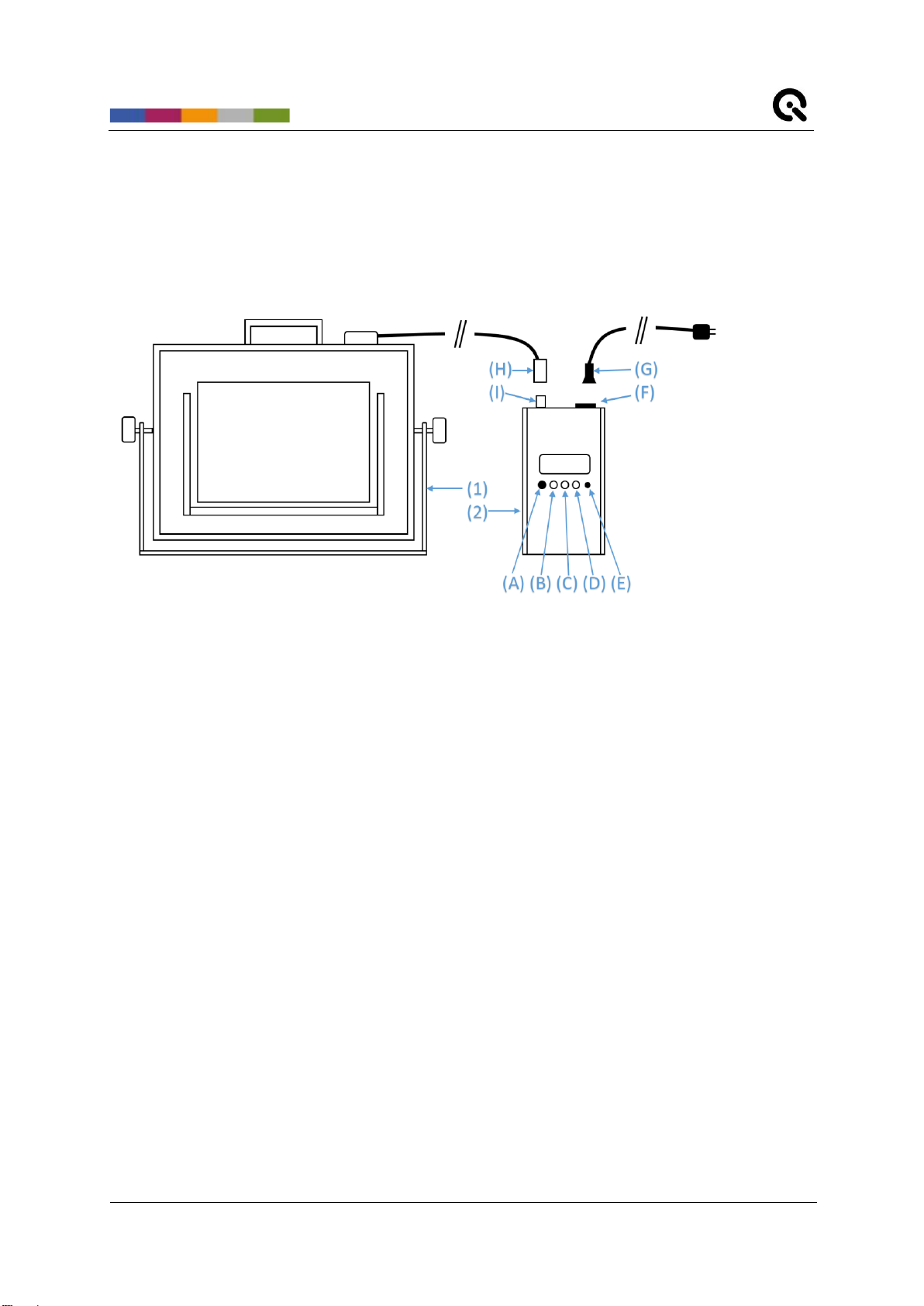
3.1 Overview............................................................................................................... 5
3.2 Connecting the hardware....................................................................................... 5
3.3 Starting the system................................................................................................ 6
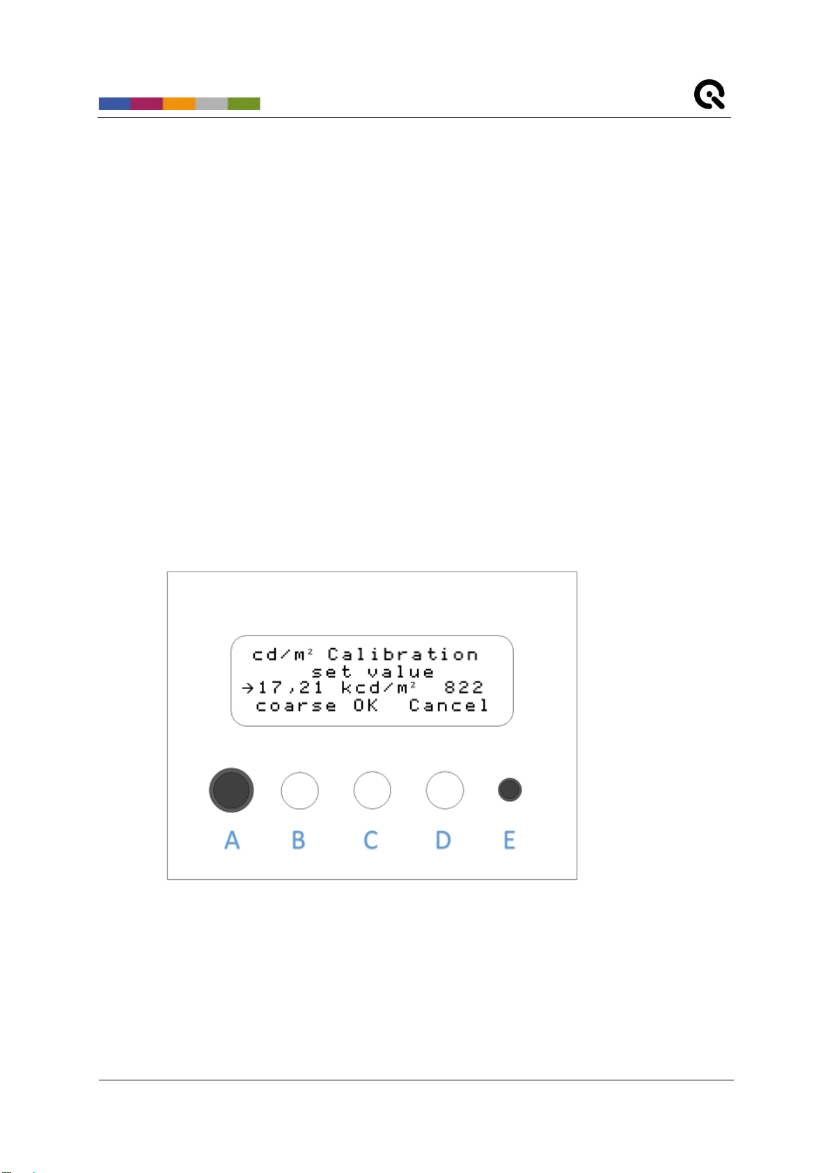
3.3.1 Calibration.......................................................................................................6
3.4 Continuous illumination.......................................................................................... 6
3.4.1 Power modes ..................................................................................................7
3.4.2 PWM (Pulse Width Modulation)........................................................................7
3.4.3 Setting the illumination level.............................................................................9
3.4.4 Intensity stabilization........................................................................................9
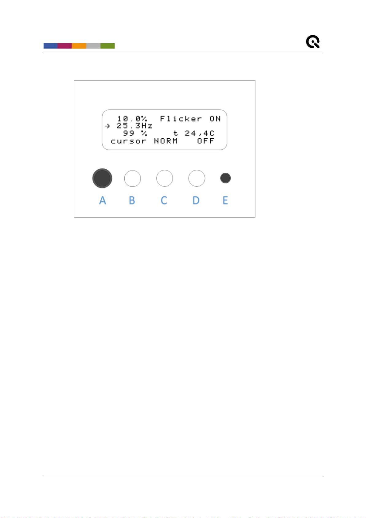
3.5 Flicker..................................................................................................................11
4ADDITIONAL INFORMATION....................................................................................13
4.1 Maintenance ........................................................................................................13
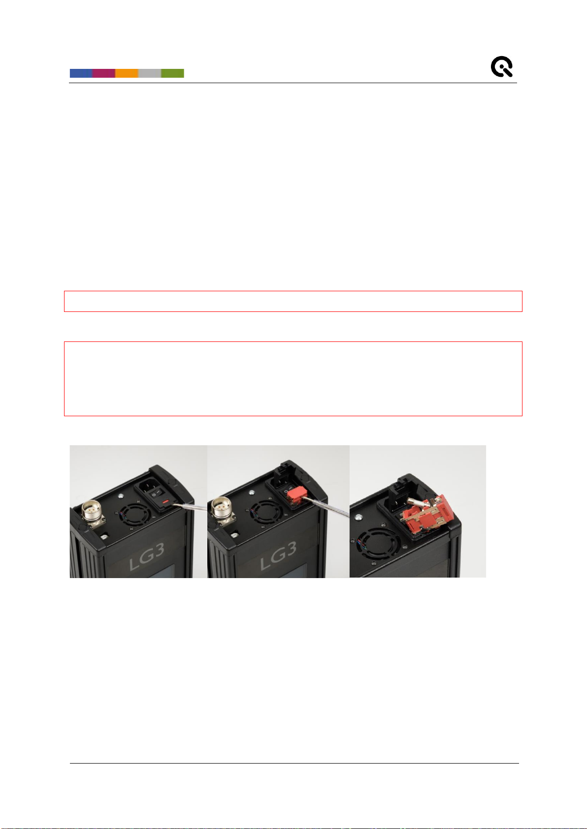
4.1.1 Fuse replacement..........................................................................................13
4.2 Storage and transport...........................................................................................14
4.3Disposal instructions.............................................................................................14
5TECHNICAL DATA SHEET........................................................................................14

Image Engineering
Seite 3von 14
1 INTRODUCTION
Important information: Read the manual carefully before using the device.
Inappropriate utilization may cause damage to the device, to the DUT (device under test), and/or other
components of your setup.
Keep these instructions in a safe place and pass them on to any future user.
1.1 Conformity
We, Image Engineering GmbH & Co. KG, hereby declare that the LG3 corresponds to the essential
requirements of the following EC directive:
•Electromagnetic Compatibility - 2014/30/EU
•Photobiological safety of lamps and lamp systems - IEC 62471:2009
1.2 Intended use
The LG3 is a high-intensity illuminator based on LED technology for transparent charts. It is capable of
flicker generation with variable frequency and variable duty cycle. The external controller unit and the
LG3 Software can control the device.
•Only suitable for indoor use.
•Place your system in a dry, constant tempered environment without light interference.
•The optimal ambient temperature range is 22 to 26 degrees Celsius. The maximum
ambient temperature range is 18 to 28 degree Celsius.
•The system has an internal temperature management system, if there is any error
regarding the internal temperature, you will get a warning message, and the system
automatically turns off to avoid any damage.
1.3 General safety information
Do not open the device without instructions from the Image Engineering support team and when
connected to the power supply.
1.3.1 Photosensitive epilepsy
A few users with pre-existing conditions may experience seizures while using the
flicker mode of the LG3. Certain frequencies and intensity combinations may trigger
seizures with no prior medical history. Reframe using the device and consult a doctor
immediately if you experience sickness while using the LG3.

Image Engineering
Seite 4von 14
1.3.2 Eye safety
The LEDs used in the LG3 can be classified as belonging to the Exempt Group or Risk Group 1,
according to IEC 62471:2009.
2 GETTING STARTED
2.1 Scope of Delivery
•LG3 control unit
•LG3 illumination unit
•Tripod handle
•Power supply cable
•USB cable
•2x spare fuses (2A)
•Flight case
•Control software
•User manual
•Calibration protocol
Optional equipment:
•LG3 Control Holder and Tripod
•LG C++ API.
2.2 Commissioning
Keep all ventilation slits of the LG3 illumination unit free of foreign objects. The minimum clearance is
15 cm.
LG3 Control Holder and Tripod

Image Engineering
Seite 5von 14
3 OPERATING INSTRUCTIONS HARDWARE
3.1 Overview
Hardware Overview
1. Illumination unit
2. Control unit
A. Multifunctional rotary/push knob
B. Multifunctional button (function is stated on the display)
C. Multifunctional button (function is stated on the display)
D. Multifunctional button (function is stated on the display)
E. Display brightness adjustment
F. Powerswitch, powersocket and fuses combination
G. Power cable
H. Ilumination unit connection cable
I. Illumination unit connection socket
3.2 Connecting the hardware
Connect the illumination unit (1) to the control unit (2):
•Plug the cable (H) into the socket (I)
•All “open”marks must face to the front side of the device
•Turn the lock ring clockwise for a secure connection

Image Engineering
Seite 6von 14
3.3 Starting the system
The power switch (F) is located on the upper side of the control unit.
3.3.1 Calibration
The LG3 has a stabilized intensity output, and the system needs to be calibrated to use the output
feedback in cd/m² or lux. The LG3 provides two calibration modes.
•Luminance calibration: Luminance is a measure of the emission or reflection from a
flat surface in cd/m². For the LG3, the chart surface is measured, but the diffuser plate
is measured for shading measurements. Therefore, it measures the emission towards
the device under test (e.g., a camera system). Choose a reference point on the chart for
the calibration. When using an OECF chart, we recommend the field with the lowest
density.
•Illuminance calibration: Illuminance measures how much light illuminates a surface in
lux. It, therefore, measures the illumination directed at the light source and is not
suitable for a measurement on the chart.
Calibration menu
•Press buttons (B) and (C) simultaneously to enter the calibration menu
•Wait until the calibration reference value is measured; this will take a few seconds
•Switch between luminance and illuminance calibration mode by pressing the rotary
knob (A)

Image Engineering
Seite 7von 14
•Measure the calibration values with a suitable measurement device (e.g., luminance
meter) on the preferred region of the chart
•With the measured value from the external measurement device, rotate the rotary knob
(A) to assign the calibration
•Switch between “fine”and “coarse”to set the sensitivity of the rotary knob (A) by
pressing the button (B)
•Press the “OK”button (C) to save the calibration and exit the calibration menu
•Press the “Cancel”button (D) to exit the calibration without saving
•The last performed calibration will be activated
The LG3 is factory calibrated. Perform an individual calibration to use it with your charts.
3.4 Continuous illumination
Use continuous illumination when illuminating test charts. The continuous illumination is preset as a
default on the LG3 start-up. Read chapter 3.5 on how to enter and exit the flicker mode.
3.4.1 Power modes
Three power modes are available
•LOW: 32 kHz PWM, variable duty cycle, stabilized illumination level
•NORM: 32 kHz PWM, variable duty cycle, stabilized illumination level with higher
intensities
•HIGH: direct current, not stabilized, high illumination level (over 150,000 lux)
oThe illumination in the high-power mode is not variable by the user and is
preset at the maximum possible intensity
oDue to the high thermal stress, the high-power mode is available for 60
seconds at a time
oThe device will not start the high-power mode if the LED temperature is too high
3.4.2 PWM (Pulse Width Modulation)
The LG3 uses pulse width modulation (PWM) to control illumination levels. The high frequency of 32
kHz allows a flicker-free image acquisition for most cameras. The constant voltage has the benefit of a
constant correlated color temperature.

Image Engineering
Seite 8von 14
LED intensity over time at 32 kHz pulse width modulation with 50% duty cycle
0 0,01 0,02 0,03 0,04 0,05 0,06 0,07 0,08 0,09 0,1
Relative Intensity
Time [ms]
Puls Width Modulation with 32 kHz (simplified
representation)
Relative Intensity Period Time_on Time_off

Image Engineering
Seite 9von 14
3.4.3 Setting the Illumination Level
The illumination level is adjustable. Set the illumination level by performing the following steps:
Default settings
•Ensure the selected chart is placed in the chart holder if it is required for your
measurement.
•Calibrate the illumination feedback (Chapter 3.3.1)
•Select the power mode by pressing the button (C)
•To enter HIGH power mode, hold button (C) for 2 seconds
•Select the illumination feedback unit by pressing the rotary knob (A). Lux and cd/m² are
available. Ensure the selected unit is calibrated with the actual setup
•Toggle the cursor with the button (B) through the settings and change the setting by
turning the rotary knob (A)
oFirst line: set the actual illumination level in percent and Lux or cd/m²
oSecond line: set the flicker frequency (0 Hz = continuous illumination as
described in chapters 0–0)
oThird line: set the flicker duty cycle. (Chapter 3.5)
•The stabilization of the set intensity may take up to 10 seconds
•Press button (D) to turn the illumination on and off.

Image Engineering
Seite 10 von 14
3.4.4 Intensity stabilization
The intensity of continuous illumination in the LOW and NORM modes is stabilized. The LG3 performs
independently of the LED temperature, but the stabilization can take from 2 up to 10 seconds. Do not
change the chart position in this period.
Light emitted by external light sources or reflected by objects in front of the LG3 can enter the
illumination unit and affect stabilization. Place the illumination unit in a dark room and avoid reflective
and moving objects in this room.

Image Engineering
Seite 11 von 14
3.5 Flicker
Camera systems are often part of safety systems, such as in the automotive or security industries.
Often, they must handle different illumination scenarios, such as traffic lights, LED street illumination,
LED stop lights, etc. Different light sources use different frequencies and duty cycles, which can affect
the image quality and cause the loss of image information.
The LG3 simulates different light sources with its capability to vary the duty cycle and frequency of the
illumination. The adjustable duty cycle settings of the 32 kHz frequency can change the illumination,
and the flicker frequency is modulated on the 32 kHz frequency.
Modulated flicker frequencies
0 0,5 1 1,5 2 2,5 3
Relative Intensity
Time [ms]
Flicker (simplified representation)
32kHz Signal / DutyCycle_Main = 50%
Resulting Flicker Signal 500Hz /DutyCycle_Flicker = 50%

Image Engineering
Seite 12 von 14
Perform the following steps to use the flicker mode for your measurement.
Set flicker frequency
•Ensure the selected chart is placed in the chart holder if your measurement requires it.
•Select the power mode by pressing the button (C)
•To enter HIGH power mode, hold the button (C) for 2 seconds
•Illumination feedback in lux and cd/m² is not available in flicker mode
•Toggle the cursor with the button (B) through the settings and change the setting by
turning the rotary knob (A)
oFirst line: set the actual illumination level in percentage
oSecond line: set the flicker frequency (0 Hz = continuous illumination as
described in chapters 0–0)
oThird line: set the flicker duty cycle.
•Press button (D) to turn the illumination on and off.
•For a quick switch between continuous and flicker mode, press the rotary knob (A)

Image Engineering
Seite 13 von 14
4 ADDITIONAL INFORMATION
4.1 Maintenance
•Do not touch, scratch, or pollute the diffuser.
•If there is any dust on the diffuser, clean it with compressed air or an air blower.
4.1.1 Fuse replacement
In the event of an overcurrent, the fuses will break to protect the device. Broken fuses need to be
replaced.
Only use T2/250E fuses.
TURN THE DEVICE OFF
DISCONNECT FROM THE POWER SUPPLY
ENSURE ALL CABLES ARE DISCONNECTED
Fuse replacement
•Lift the fuse cover located over the power switch using a small flathead screwdriver
•Lift the red fuse holder using a small flathead screwdriver
•Replace the defected fuse
•Place the fuse holder back into the fuse holder socket
•Close the fuse cover

Image Engineering
Seite 14 von 14
4.2 Storage and transport
•Store and transport the LG3 only in the delivered hard case.
4.3 Disposal instructions
The LG3 must be disposed of properly after the service life is over. Electrical and electromechanical
components are included in LG3. Observe your national regulations and ensure that third parties
cannot use LG3 after disposing of it.
Contact Image Engineering if assistance for disposal is required.
5 TECHNICAL DATA SHEET
See annex for the technical data sheet. It can also be downloaded from the website of Image
Engineering: https://image-engineering.de/support/downloads.
Table of contents
Popular Industrial Electrical manuals by other brands

Murata
Murata GJM0335C1H1R0WB01 Series Reference sheet

Murata
Murata GRT188C8YA105ME13 Series Reference sheet

Murata
Murata GRJ188R72A222KE11 Series Reference sheet

Murata
Murata GRM219R71E105KA88 Series Reference sheet

Ampetronic
Ampetronic ILD15 Series Handbook

Murata
Murata GQM1875C2E430GB12 Series Reference sheet

Softing
Softing FG-200 HSE/FF user manual

Murata
Murata GRM188R71H823KA93 Series Reference sheet

YOKOGAWA
YOKOGAWA Juxta MH7 user manual

Peter electronic
Peter electronic VB 230-6LT Assembly and commissioning instructions

PR electronics
PR electronics 9202 Series manual

Murata
Murata GRM0335C1E9R2DA01 Series Reference sheet