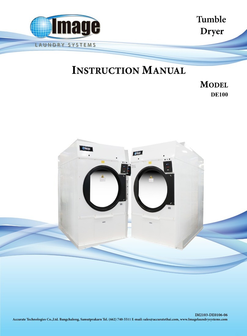
Image DE 30 User manual


PAGE
SECTION 1: IMPORTANT INFORMATION 1-1
A. RECEIVING AND HANDLING 1-1
B. SAFETY PRECAUTIONS 1-1
SECTION 2: SPECIFICATIONS / COMPONENT IDENTIFICATION 2-1
A. TECHNICAL SPECIFICATIONS 2-1
B. TECHNICAL DIMENSION 2-2
C. COMPONENT IDENTIFICATION 2-5
SECTION 3: INSTALLATION PROCEDURES 3-1
A. LOCATION REQUIREMENTS 3-1
B. UNPACKG / SETTING UP 3-2
C. DRYER ENCLOSUE REQUIREMENTS 3-2
D. FRSH AIR SUPPLY 3-3
E. EXHAUST REQUIREMENTS 3-4
F. ELECTRICAL INFORRMATION 3-10
G. GAS INFORMATION 3-16
H. STEAM INFORMATION 3-19
I. PREPARATION FOR OPERTION / START UP 3-22
J. PRE - OPERATIONAL TESTS 3-23
SECTION 4: OPERATING AND PROGRAMMING INSTRUCTIONS 4-1
A. OPERATING INSTRUCTIONS 4-1
B. SHUTDOWN INSTRUCTIONS 4-2
C. SETTING THE PROGRAM 4-3
D. SETTING THE CONTROLLER 4-4
E. MEANING OF THE ALARM MASSAGES 4-4
SECTION 5: WARRANTY INFORMATION 5-1
A. RETURNING WARRANTY CARD(S) 5-1
B.WARRANTY 5-1
C. RETURNING WARRANTY PART(S) 5-1
SECTION 6: ROUTINE MAINTENANCE 6-1
A.CLEANING 6-1
B. ADJUSTMENTS 6-2
C.LUBRICATION 6-2
SECTION 7: TROUBLE SHOOTING 7-1
A. MICROPROCESSOR MODELS 7-1
B. TIMER MODELS 7-5
SECTION 8: SERVICE / PART INFORMATION
A.SERVICE
B. PARTS LIST

I
เครื่องหมายละสัญลักษณ
Anyone operating or servicing this machine must follow the safety rules in this manual.
Particular attention must be paid to the DANGER, and WARING, and CAUTION blocks which
appear throughout the manual.
Symbols Description
This warning symbol indicated the presence of hot surfaces
that could cause serious burns. Stainless steel and steam lines
can become extremely got and should not be touched.
IMPORTANT! Keep lint compartment clean
WARNING! Dry only water washed fabrics. Do not use heat
for drying foam rubber or similar textured rubber like
materials.
Information Alert to the correct direction of rotation.
DANGER! High voltage present.
DANGER! For the hand, Belts and pulley in motion.
Do Not operate with out Guard.

II
Symbols Description
WARNING! Put DRYCLEANED Laundry into this dryer
Information The machine is use 24 VAC. for control.
IMPORTANT! Clean cylinder and check tumbler dryer
operation by running a load of wet cloths at full heat for 20
minutes.
WARNING! To reduce the risk of electric shock, disconnect
electric power before servicing
WARNING! This dryer must be exhausted to the outdoors.
Exhaust ductwork should be examined and cleaned, if
necessary, every three months after installation. Do not distort
thimble when installing ductwork. Make sure thimble vanes
open and close freely after ductwork has been installed.

IMPORTANT INFORMATION
1-1
SECTION 1
IMPORTANT INFORMATION
The dryer is shipped in a protective stretch wrap cover with protective cardboard comers and
top cover (or optional box) as a means of preventing damage in transit. Upon delivery, the dryer and
/ or protective packaging, and wooden skid should be visually inspected for shipping damage. If
any damage whatsoever is noticed, inspect further before delivering carrier leaves.
Dryers damaged in shipment:
1. All dryers should be inspected upon receipt and before they are signed for.
2. If there is suspected damage or actual damage, the trucker’s receipt should be so noted.
3. If the dryer is damaged beyond repair, it should be refused. Those dryers which were not
damaged in a damaged shipment should be accepted, but the number received and number
refused must be noted on the receipt.
4. If you determine that the dryer was damaged after the trucker has left your location, you
should call the delivering carrier’s freight terminal immediately and file a claim. The freight
company considers this concealed damage. This type of freight claim is very difficult to get
paid and becomes extremely difficult when more than a day or two passes after the freight was
delivered. It is your responsibility to file freight claims. Dryers / parts damaged in transit
cannot be claimed under warranty.
5. Freight claims are the responsibility of the consignee, and all claims must be filed at the
receiving end.
Dryer assumes no responsibility for freight claims or damages.
6. If you need assistance in handling the situation, please contact the Dryer traffic manager.
IMPORTANT: The dryer must be transported and handled in an upright position at all times.
WARNING: For your safety, the information in this manual must be followed to minimize the
risk of fire or explosion or to prevent property damage, personal injury or loss of life.
WARNING: The dryer must never be operated with any of the back guards, outer tops, or service
panels removed. PERSONAL INJURY or FIRE COULD RESULT.
1. DO NOT store or use gasoline or other flammable vapors and liquids in the vicinity of this or
any other appliance.
2. Purchaser / user should consult the local gas supplier for proper instructions to be followed in
the event the user smells gas. The instructions should be posted in a prominent location.
A. RECEIVING AND HANDLING
B. SAFETY PRECAUTIONS

IMPORTANT INFORMATION
1-2
3. What To Do If You Smell Gas:
a. DO NOT tries to light any appliance.
b. DO NOT touches any electrical switch.
c. DO NOT uses any phone in your building.
d. Clear the room, building or area of all occupants.
e. Immediately call your gas supplier from a neighbor’s phone. Follow the gas supplier’s
instructions.
f. If you cannot reach your gas supplier, call the fire department.
4. Installation and service must be performed by a qualified installer, service agency, or the gas
supplier.
5. Dryer(s) must be exhausted to the outdoors.
6. Although Dryer produces a very versatile machine, there are some articles that, due to fabric
compositional cleaning method, should not be dried in it.
WARNING: Dry only water – washed fabrics. DO NOT dry articles spotted or washed in dry
cleaning solvents, a combustible detergent, or “all purpose” cleaner. EXPLOSION
COULD RESULT.
WARNING: DO NOT dry rags or articles coated or contaminated with gasoline, kerosene, oil,
paint, or wax. EXPLOSION COULD RESULT.
WARNING: DO NOT dry mop heads. Contamination by wax or flammable solvents will create a
fire hazard.
WARNING: DO NOT use heat for drying articles that contain plastic, foam, sponge rubber, or
similarly textured rubber materials. Drying in a heated basket (tumbler) may damage
plastics or rubber and also may be a fire hazard.
7. A program should be established for the inspection and cleaning of the lint in the burner area,
exhaust ductwork and area around the back of the dryer. The frequency of inspection and
cleaning can best be determined from experience at each location.
WARNING: The collection of lint in the burner area and exhaust ductwork can create a potential
fire hazard.
8. For personal safety, the dryer must be electrically grounded in accordance with local codes and
/ or the National Electric Code ANSI/NFPA NO. 70 – LATEST EDITION, or in Canada, the
Canadian Electrical Codes Parts 1 & 2 CSA C22.1 – 1990 or LATEST EDITION. And/or the
Australian standard for lighting protection AS 1768-2007 or Latest Edition.
NOTE: Failure to do so will. VOID THE WARRANTY.
9. Under no circumstances should the dryer door switch, lint drawer switch or heat circuit safety
devices ever be disabled.
WARNING: PERSONAL INJURY or FIRE COULD RESULT.
10. This dryer is not to be used in the presence of dry cleaning solvents or fumes.
11. Remove articles from the dryer as soon as the drying cycle has been completed.

IMPORTANT INFORMATION
1-3
WARNING: Articles left in the dryer after the drying and cooling cycles have been completed can
create a fire hazard.
12. DO NOT operates steam dryers with more than 125 Psi steam pressure. Excessive steam
pressure can damage steam coil and / or harm personnel.
13. Replace leaking flexible steam hoses or other steam fixtures immediately. DO NOT operate
dryer with leaking flexible hoses. PERSONAL INJURY MAY RESULT.
14. Read and follow all caution and direction label attached to Dryer.
IMPORTANT: You must disconnect and lockout the electric supply and the gas supply or the
steam supply before any covers or guards are remove from the machine to allow
access to cleaning, adjusting, installation, or testing of any equipment per OSHA
(Occupational Safety and Health Administration) STANDARDS.

SPECIFICATIONS / COMPONENT IDENTIFICATION
2-1
SECTION 2
SPECIFICATIONS / COMPONENT IDENTIFICATION
MODEL METRIC US DE30 lb. DE50 lb. DE75 lb.
Maximum Capacity (dry weight) kg lbs 13.9(35) 23(50) 34(75)
Basket Diameter mm. inch 762(30) 922(36.3) 922(36.3)
Basket Depth mm. inch 762(30) 762(30) 910(35.8)
Basket Volume cu. m. cu. ft. 0.34(12.2) 0.5(18) 0.6(21.5)
GAS:
Air Flow cmm. cfm 17(600) 21.25(750) 25(900)
Heat Input kcal / hr Btu / hr. 2260(90000) 32760(130000) 50400(200000)
Gas Inlet mm. inch 12.7(0.5) 12.7(0.5) 19(0.75)
Exhaust Duct mm. inch 203(8) 203(8) 203(8)
A – Machine Height mm. inch 1850(72.83) 2100(82.67) 1915(75.39)
B – Machine Depth mm. inch 1120(44.09) 1190(46.85) 1270(50)
C – Machine Width mm. inch 800(31.19) 1000(39.37) 1000(39.37)
Net Weight (approx.) Kg. lbs. 294(648) 348(767) 379(835)
Shipping Weight (approx.) kg lbs 304(670) 358(789) 390(860)
STEAM:
Air Flow cmm cfm 17(600) 21.25(750) 25(900)
Steam consumption BHP BHP 2.6 4.6 6.5
Operating Pressure kg / cm²psi 5.6-8.79(80-125) 5.6-8.79(80-125) 5.6-8.79(80-125)
Steam supply mm. inch 19.05(0.75) 19.05(0.75) 19.05(0.75)
Steam return mm. inch 12.7(0.5) 12.7(0.5) 12.7(0.5)
Exhaust Duct mm. inch 203(8) 203(8) 203(8)
A – Machine Height at full mm. inch 1900(74.8) 2200(86.61) 2140(84.25)
B – Machine Depth mm. inch 1120(44.09) 1150(45.27) 1270(50)
C – Machine Width mm. inch 800(31.19) 1000(39.37) 1000(39.37)
Net Weight (approx.) Kg. lbs. 307(677) 362(798) 385(849)
Shipping Weight (approx.) Kg. lbs. 315(694) 372(820) 396(873)
ELECTRICAL:
Air Flow cmm. Cfm 17(600) 21.25(750) 25(900)
A – Machine Height at full mm. inch 1880(46.45) 2100(82.67) 2100(82.67)
B – Machine Depth mm. inch 1120(44.09) 1150(45.27) 1270(50)
C – Machine Width mm. inch 800(31.19) 1000(39.37) 1000(39.37)
Net Weight (approx.) Kg. lbs. 308(679) 354(780) 382(842)
Shipping weight (approx.) Kg. Ibs. 317(699) 364(802) 393(866)
A. TECHNICAL SPECIFICATIONS

SPECIFICATIONS / COMPONENT IDENTIFICATION
2-2
1. Dryer Model DE30 lb. Technical Dimension
Figure.2-1 Dryer Model DE30 lb. Technical Dimension
B. TECHNICAL DIMENSION

SPECIFICATIONS / COMPONENT IDENTIFICATION
2-3
2. Dryer Model DE50 lb. Technical Dimension
Figure.2-2 Dryer Model DE50 lb. Technical Dimension

SPECIFICATIONS / COMPONENT IDENTIFICATION
2-4
3. Dryer Model DE75 lb. Technical Dimension
Figure.2-3 Dryer Model DE75 lb. Technical Dimension

SPECIFICATIONS / COMPONENT IDENTIFICATION
2-5
1. Dryer Model DE30, 50, 75 lb. Dryer Front View
No. Description
1 Timer controller
2. Front panel assembly, top
3. Front panel assembly, middle
4. Main door assembly
5. Front panel assembly, lower
6. Right side panel assembly
7. Left side panel assembly
Figure.2-4 Dryer Model DE30, 50, 75 lb. Front View
C. COMPONENT IDENTIFICATION
1
2
2
3
3
4
4
5
6
7
1
5

SPECIFICATIONS / COMPONENT IDENTIFICATION
2-6
2. Dryer Model DE30, 50, 75 lb. Dryer Rear View
No. Description
1. Blower & Basket motor (1 Ph)
2. Blower motor (3 Ph)
3. Basket motor (3 Ph)
4. Heating element (Electric, Gas, Steam
5. Electrical box
6. Cover, Top
7. Back guard upper
8. Back guard lower
9. Exhaust duct outlet
Figure.2-5 Dryer Model DE30, 50, 75 lb. Rear View
7
9
6
8
9
9
23
5
1
4 4

INSTALLATION PROCEDURES
3-1
SECTION 3
INSTALLATION PROCEDURES
Installation should be performed by competent technicians in accordance with local and
state codes. In the absence of these codes, installation must conform to applicable American
National Standards: ANSI Z223.1 – LATEST EDITION (National Fuel Gas Code) or ANSI/NFPA
NO.70 – LATEST EDITION (National Electrical Code) or in Canada, the installation must
conform to applicable Canadian Standards: CAN/CGA – B149.1 – M91 (Natural Gas) or
CAN/CGA – BI49.2 – M91 (L.P. Gas) or LATEST EDITION (for General Installation and Gas
Plumbing) or Canadian Electrical Code Parts 1 & 2 CSA C22.1 – 1990 or LATEST EDITION (for
Electrical Connections).
Before installing the dryer, be sure the location conforms to local codes and ordinances. In
absence of such codes or ordinances location must conform with the National Fuel Gas Code
ANSI Z223.1 – LATEST EDITION, or in Canada, the Canadian Installation Codes CAN/CGA –
B149.1 – M91 (Natural Gas) or CAN/CGA – B149.2 – M91 (L.P. Gas) or LATEST EDITION (for
General Installation and Gas Plumbing).
1. The dryer must be installed on a sound level floor capable of supporting its weight. It is
recommended that carpeting be removed from the floor area that the dryer is to rest on.
2. The dryer must not be installed or stored in an area where it will be exposed to water and / or
weather.
3. This dryer is for use in noncombustible locations.
4. Provisions for adequate air supply must be provided as noted in this manual (refer to Fresh
Air Supply in Section D).
5. Clearance provisions must be made from combustible construction as noted in this manual
(refer to Dryer Enclosure Requirements in Section C).
6. Provisions must be made for adequate clearances for servicing and for operation as noted in
this manual (refer to Dryer Enclosure Requirements in Section C).
7. Dryer must be exhausted to the outdoors (refer to Exhaust Requirements in Section E).
8. Dryer must be located in an area where correct exhaust venting can be achieved as noted in
this manual (refer to Exhaust Requirements in Section E).
IMPORTANT: Dryer should be located where a minimum amount of exhaust duct will be
necessary.
A. LOCATION REQUIRMENTS

INSTALLATION PROCEDURES
3-2
Remove protective shipping material (i.e., plastic wrap and / or optional shipping box) from
dryer.
1. Unscrew nut the wood piece before operating the machine.
2. Take out the wood piece before operating the machine.
Figure.3-1 Protective Shipping Material
IMPORTANT: Dryer must be transported and handled in an upright position at all times.
Bulkheads and partitions should be made of noncombustible materials and must be located
a minimum of twelve (12) inches above the dryer outer top, except along the front of the dryer
which may be closed in if desired.
X = 12”, 2.4” for ease of maintenance
Y = 12” for gas dryers, 18” for steam dryers
Z=2”
Figure.3-2 Dryer enclosure requirements
B. UNPACKING / SETTING UP
C. DRYER ENCLOSURE REQUIREMENTS

INSTALLATION PROCEDURES
3-3
TYPICAL INSTALLATION SHOWING MAKE-UP AIR OPENINGS
NOTE: Air considerations are important for proper and efficient operation.
When the dryer is operating, it draws in room air, heats it, passes this air, through the
tumbler (basket), and exhausts it out of the building. Therefore, the room air must be continually
replenished from the outdoors.
If the make – up air is inadequate, drying time and drying efficiency will be adversely
affected. Ignition problems and sail switch “fluttering” problems on gas dryers may result, and you
also could have premature motor failure from overheating.
Air supply (make – up air) must be given careful consideration to assure proper
performance of each dryer. An unrestricted source of air is necessary for each dryer. As a general
rule, an unrestricted air entrance from the outdoors (atmosphere) of a minimum of one (1) square
foot (1 – 1/2 for the Model 75) is required for each dryer. If registers or louvers are installed over
the openings, then the area must be increased. It is not necessary to have a separate make – up air
opening for each dryer. Common make – up air openings are acceptable. However, they must be
set up in such a manner that the make – up air is distributed equally to the dryers.
EXAMPLE: for a bank of eight (8) dryers, two (2) openings measuring 2” × 2” (4 square feet) are
acceptable. Refer to the illustration on next page for details.
Allowances must be made for remote or constricting passageways or where dryers are
located at excessive altitudes or predominantly low – pressure areas.
IMPORTANT: Make – up air must be provided from a source free of dry cleaning fumes.
Make – up air that is contaminated by dry cleaning fumes will result in irreparable
damage to motors and other dryer components.
Figure.3-3 Typical installations make up air openings
NOTES: Component failure due to dry cleaning fumes VOIDS THE WARRANTY.
D. FRESH AIR SUPPLY

INSTALLATION PROCEDURES
3-4
Exhaust duct work should be designed and installed by a competent technician. Improperly
sized duct work will create excessive back pressure which will result in slow drying, increased use
of energy, and shutdown of the burner by the airflow (sail) switch, burner hi – limit, or lint chamber
hi – heat protector thermostat. Refer to the illustrations on next pages for details.
Dryer Exhaust Duct Size: 6”
Dryer Air Flow: 375 cfm.
Model Number: DE30 lb., DE50 lb.
Heat Reclaimer: Yes
Controls: OPL
Figure.3-4 Multiple exhaust connection.
E. EXHAUST REQUIREMENTS

INSTALLATION PROCEDURES
3-5
Dryer Exhaust Duct Size: 6”
Dryer Air Flow: 600 cfm.
Model Number: DE30 lb., DE50 lb.
Heat Reclaimer: No.
Controls: OPL
Figure.3-5 Multiple exhaust connection.

INSTALLATION PROCEDURES
3-6
Dryer Exhaust Duct Size: 8”
Dryer Air Flow: 600 cfm.
Model Number: DE30 lb., DE50 lb.
Heat Reclaimer: No.
Controls: OPL
Figure.3-6 Multiple exhaust connection.

INSTALLATION PROCEDURES
3-7
Dryer Exhaust Duct Size: 8”
Dryer Air Flow: 900 cfm.
Model Number: DE75 lb.
Heat Reclaimer: Yes
Controls: OPL
Figure.3-7 Multiple exhaust connection.
This manual suits for next models
2
Table of contents
Other Image Dryer manuals