Imagine Selenio 6800+ User manual

InstallationandOperationManual
Selenio6800+
VRG6800+
AnalogVideoRemoteGainandEQDistributionAmplifier
EditionE
175‐100500‐00

PublicationInformation
©2014ImagineCommunicationsCorp.ProprietaryandConfidential.
ImagineCommunicationsconsidersthisdocumentanditscontentstobeproprietaryand
confidential.Exceptformakingareasonablenumberofcopiesforyourowninternaluse,you
maynotreproducethispublication,oranypartthereof,inanyform,byanymethod,forany
purpose,orinanylanguageotherthanEnglishwithoutthewrittenconsentofImagine
Communications.Allothersusesareillegal.
Thispublicationisdesignedtoassistintheuseoftheproductasitexistsonthedateof
publicationofthismanual,andmaynotreflecttheproductatthecurrenttimeoranunknown
timeinthefuture.Thispublicationdoesnotinanywaywarrantdescriptionaccuracyor
guaranteetheusefortheproducttowhichitrefers.ImagineCommunicationsreservesthe
right,withoutnoticetomakesuchchangesinequipment,design,specifications,components,
ordocumentationasprogressmaywarranttoimprovetheperformanceoftheproduct.
Trademarks
SelenioTMandSelenio6800+TMaretrademarksofImagineCommunicationsoritssubsidiaries.
Microsoft®andWindows®areregisteredtrademarksofMicrosoftCorporation.Allother
trademarksandtradenamesarethepropertyoftheirrespectivecompanies.
ContactInformation
ImagineCommunicationshasofficelocationsaroundtheworld.Forlocationsandcontact
informationsee:http://www.imaginecommunications.com/contact‐us/
SupportContactInformation
Forsupportcontactinformationsee:
SupportContacts:http://www.imaginecommunications.com/services/technical‐support/
eCustomerPortal:http://support.imaginecommunications.com

VRG6800+Installation and Operation Manual iii
Preliminary—Contents are proprietary and confidential. Do not photocopy or distribute.
Contents
Preface
Manual Information ...................................................................... v
Unpacking/Shipping Information ............................................... vii
Safety Standards and Compliances ........................................... viii
Chapter 1: Introduction
Overview ....................................................................................... 1
Product Description ...................................................................... 2
Typical Broadcast and Production Applications .................... 2
Main Features ......................................................................... 2
Module Descriptions .................................................................... 3
Front Module ......................................................................... 3
Back Modules ........................................................................ 4
Block Diagram .............................................................................. 6
Chapter 2: Installation and Operation
Overview ....................................................................................... 7
Maximum 6800+Frame Power Ratings ...................................... 8
Unpacking the Module ................................................................. 9
Preparing the Product for Installation .................................... 9
Checking the Packing List ..................................................... 9
Setting Modes ............................................................................. 10
Setting Jumpers .................................................................... 10
Setting the Rotary Selector Switch ...................................... 12
LEDs and Alarms ....................................................................... 14
Module Status LED .............................................................. 14

iv VRG6800+Installation and Operation Manual
Preliminary—Contents are proprietary and confidential. Do not photocopy or distribute.
Contents
Alarms ..................................................................................14
Other LED Descriptions .......................................................14
Installing 6800+ Modules ...........................................................15
Required Frames and Back Connector Types ......................15
Installing VRG6800+Modules ............................................15
Removing VRG6800+Modules ..........................................15
Making Connections ....................................................................15
Chapter 3: Specifications
Overview......................................................................................17
Inputs ...........................................................................................18
Outputs .........................................................................................18
Performance ................................................................................19
Temperature ................................................................................20
Start-Up Time ..............................................................................20
Index
Keywords ....................................................................................21

VRG6800+Installation and Operation Manual v
Preliminary—Contents are proprietary and confidential. Do not photocopy or distribute.
Preface
Manual Information
Purpose
This manual details the features, installation procedures, operational
procedures, and specifications of the VRG6800+analog video remote
gain and EQ distribution amplifier.
Audience
This manual is written for engineers, technicians and operators
responsible for the installation, setup, and/or operation of the
VRG6800+analog video remote gain and EQ distribution amplifier.
Revision History
Table P-1. Manual Revision History
Edition Date Revision History
A May 2003 Initial release
B July 2003 Removed references to 177 Mb/s
automatic/manual reclock rate setting
C March 2006 • Added index
• Added RoHS/WEEE compliance
information
D July 2007 • Updated input specifications
• Updated frame power ratings
E September 2014 Additional specifications
vi VRG6800+Installation and Operation Manual
Preliminary—Contents are proprietary and confidential. Do not photocopy or distribute.
Preface
Writing Conventions
To enhance your understanding, the authors of this manual have
adhered to the following text conventions:
Obtaining Documents
Technical documents can be viewed or downloaded from our website.
Alternatively, contact your Customer Service representative to request a
document.
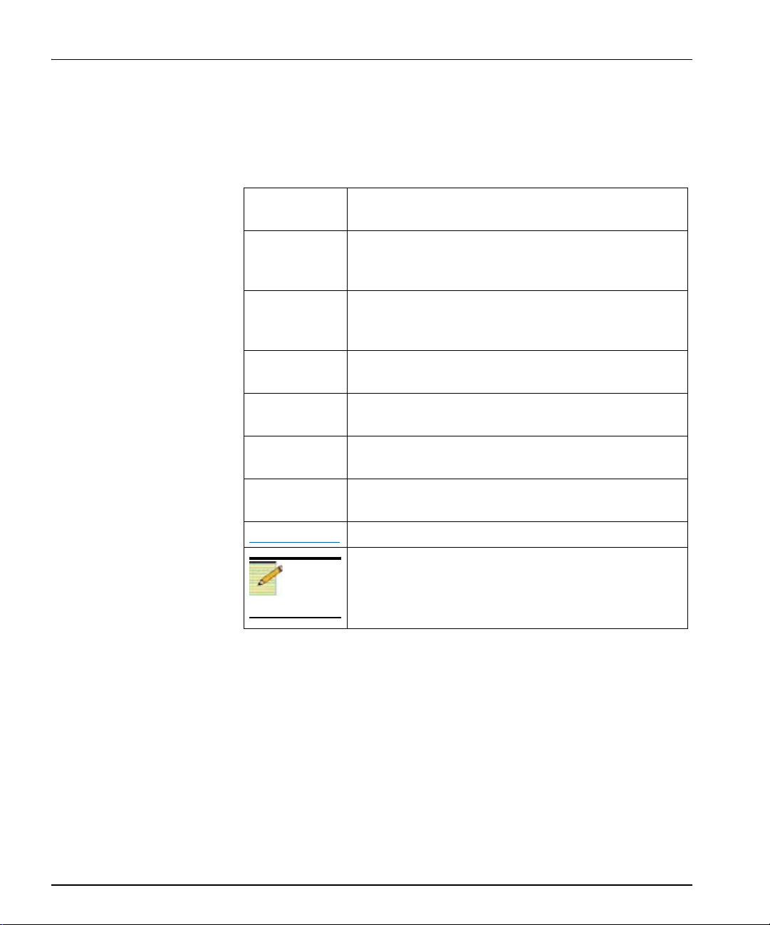
Table P-2. Manual Style and Writing Conventions
Term or
Convention Description
Bold Indicates dialog boxes, property sheets, fields, buttons,
check boxes, list boxes, combo boxes, menus, submenus,
windows, lists, and selection names.
Italics Indicates email addresses, the names of books or
publications, and the first instances of new terms and
specialized words that need emphasis.
CAPS Indicates a specific key on the keyboard, such as ENTER,
TAB, CTRL, ALT, or DELETE.
Code Indicates variables or command-line entries, such as a
DOS entry or something you type into a field.
> Indicates the direction of navigation through a hierarchy
of menus and windows.
hyperlink Indicates a jump to another location within the electronic
document or elsewhere
Internet address Indicates a jump to a Web site or URL
Note
Indicates important information that helps to avoid and
troubleshoot problems.

VRG6800+Installation and Operation Manual vii
Preface
Preliminary—Contents are proprietary and confidential. Do not photocopy or distribute.
Unpacking/Shipping Information
This product was carefully inspected, tested, and calibrated before
shipment to ensure years of stable and trouble free service.
1. Check equipment for any visible damage that may have occurred
during transit.
2. Confirm that you have received all items listed on the packing list.
3. Contact your dealer if any item on the packing list is missing.
4. Contact the carrier if any item is damaged.
5. Remove all packaging material from the product and its associated
components before you install the unit.
Keep at least one set of original packaging, in the event that you need to
return a product for servicing. If the original packaging is not available,
you can purchase replacement packaging at a modest cost or supply
your own packaging as long as it meets the following criteria:
• Withstands the weight of the product
• Holds the product rigid within the packaging
• Leaves at least two inches of space between the product and the
container
• Protects the corners of the product
Ship products back to us for servicing prepaid and, if possible, in the
original packaging material. If the product is still within the warranty
period, we will return the product prepaid after servicing.
viii VRG6800+Installation and Operation Manual
Preliminary—Contents are proprietary and confidential. Do not photocopy or distribute.
Preface
Safety Standards and Compliances
See the Selenio 6800+Safety Instructions and Standards Manual to
find the safety standards and compliances for this 6800+series product.
This document is provided in the Manuals and Product Resources
DVD, and is available on the Imagine Communications website.
Safety Terms and Symbols
This product manual uses the following safety terms and symbols to
identify certain conditions or practices. See the Selenio 6800+Safety
Instructions and Standards Manual for more information.
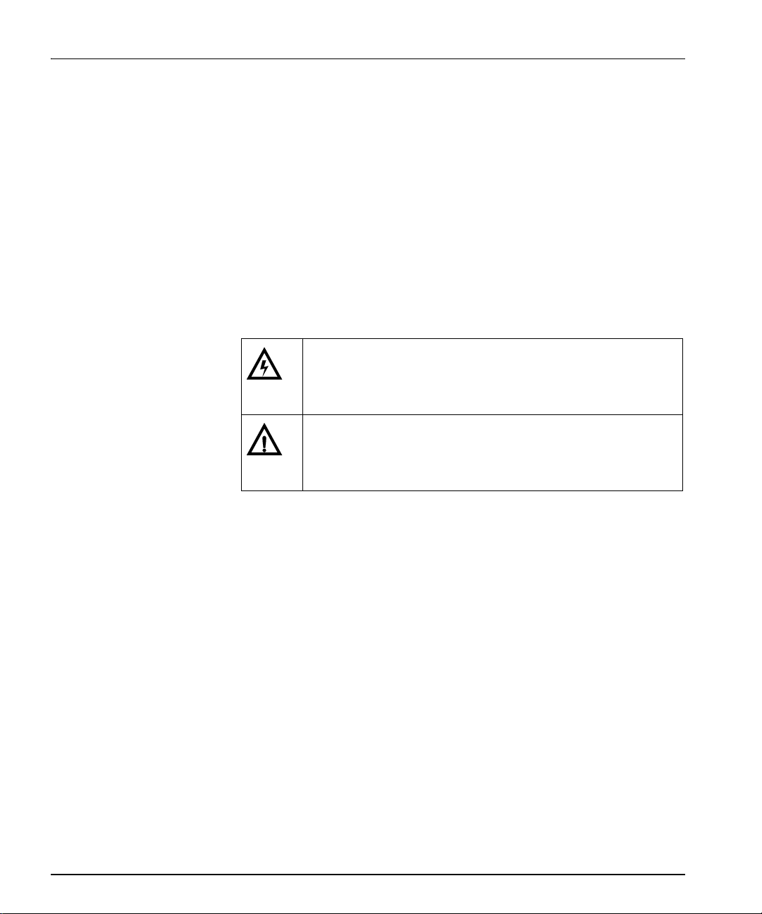
Table P-3. Safety Terms and Symbols
WARNING: Identifies conditions or practices that can result in
personal injury or loss of life—high voltage is present.
Uninsulated dangerous voltage within the product’s enclosure
may be sufficient to constitute a risk of electric shock to persons.
CAUTION: Identifies conditions or practices that can result in
damage to the equipment or other property. Important operating
and maintenance (servicing) instructions are included in the
literature accompanying the product.

VRG6800+Installation and Operation Manual ix
Preface
Preliminary—Contents are proprietary and confidential. Do not photocopy or distribute.
Restriction on Hazardous Substances (RoHS) Directive
Directive 2011/65/EU (ROHS 2)—commonly known as the European
Union (EU) Restriction on Hazardous Substances (RoHS)—sets limits
on the use of certain substances found in electrical and electronic
equipment. The intent of this legislation is to reduce the amount of
hazardous chemicals that may leach out of landfill sites or otherwise
contaminate the environment during end-of-life recycling. The
Directive, which took effect on July 1, 2006, refers to the following
hazardous substances:
• Lead (Pb)
• Mercury (Hg)
• Cadmium (Cd)
• Hexavalent Chromium (Cr-VI)
• Polybrominated Biphenyls (PBB)
• Polybrominated Diphenyl Ethers (PBDE)
According to this EU Directive, all products sold in the European Union
will be fully RoHS-compliant and “lead-free.” (See our website for
more information on dates and deadlines for compliance.) Spare parts
supplied for the repair and upgrade of equipment sold before July 1,
2006 are exempt from the legislation. Equipment that complies with the
EU directive will be marked with a RoHS-compliant emblem, as shown
in Figure P-1.
Figure P-1. RoHS Compliance Symbol
x VRG6800+Installation and Operation Manual
Preliminary—Contents are proprietary and confidential. Do not photocopy or distribute.
Preface
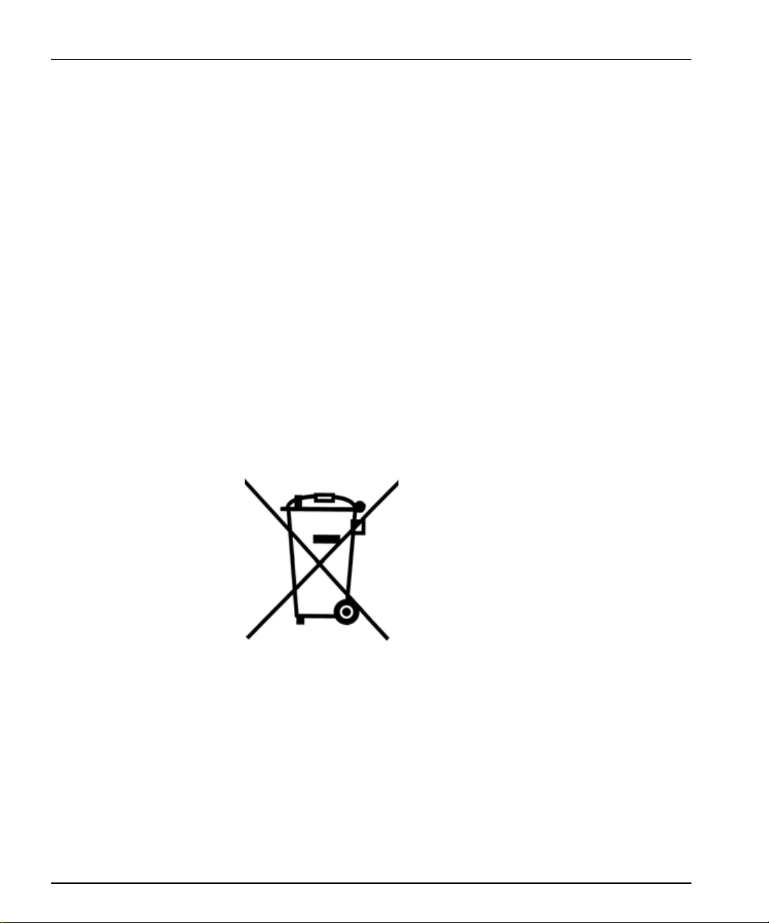
Waste from Electrical and Electronic Equipment (WEEE)
Directive
The European Union (EU) Directive 2002/96/EC on Waste from
Electrical and Electronic Equipment (WEEE) deals with the collection,
treatment, recovery, and recycling of electrical and electronic waste
products. The objective of the WEEE Directive is to assign the
responsibility for the disposal of associated hazardous waste to either
the producers or users of these products. As of August 13, 2005, the
producers or users of these products were required to recycle electrical
and electronic equipment at end of its useful life, and may not dispose
of the equipment in landfills or by using other unapproved methods.
(Some EU member states may have different deadlines.)
In accordance with this EU Directive, companies selling electric or
electronic devices in the EU will affix labels indicating that such
products must be properly recycled. (See our website for more
information on dates and deadlines for compliance.) Contact your local
Sales representative for information on returning these products for
recycling. Equipment that complies with the EU directive will be
marked with a WEEE-compliant emblem, as shown in Figure P-2.
Figure P-2. WEEE Compliance Symbol

VRG6800+Installation and Operation Manual 1
Preliminary—Contents are proprietary and confidential. Do not photocopy or distribute.
Chapter 1
Introduction
Overview
The VRG6800+is an analog video remote gain and EQ distribution
amplifier.
The following topics are described in this chapter:
•“Block Diagram” on page 6
•“Main Features” on page 2
•“Module Descriptions” on page 3
•“Product Description” on page 2

2 VRG6800+Installation and Operation Manual
Preliminary—Contents are proprietary and confidential. Do not photocopy or distribute.
Chapter 1: Introduction
Product Description
The VRG6800+is an analog video remote gain and EQ distribution
amplifier. Its gain, cable equalizer, and clamping timing can be
adjustable either at card edge, or remotely, using compatible software
and hardware control systems.
Typical Broadcast and Production Applications
The VRG6800+distribution amplifier can be used in broadcast, cable,
production, educational, and auditorium applications where a low cost
method for distribution of analog video signals is required.
Main Features
On the VRG6800+, the input is looping and internal terminating
selectable with a dual slot back module, and internal terminating with a
single slot back module. This distribution amplifier detects the input
composite video signal. Because of its excellent video performance, it
is suitable to distribute any analog composite, component (SD/HD),
and graphic video. It is also can be used for RF, and even some digital
signals.
VRG6800+Installation and Operation Manual 3
Chapter 1: Introduction
Preliminary—Contents are proprietary and confidential. Do not photocopy or distribute.
Module Descriptions
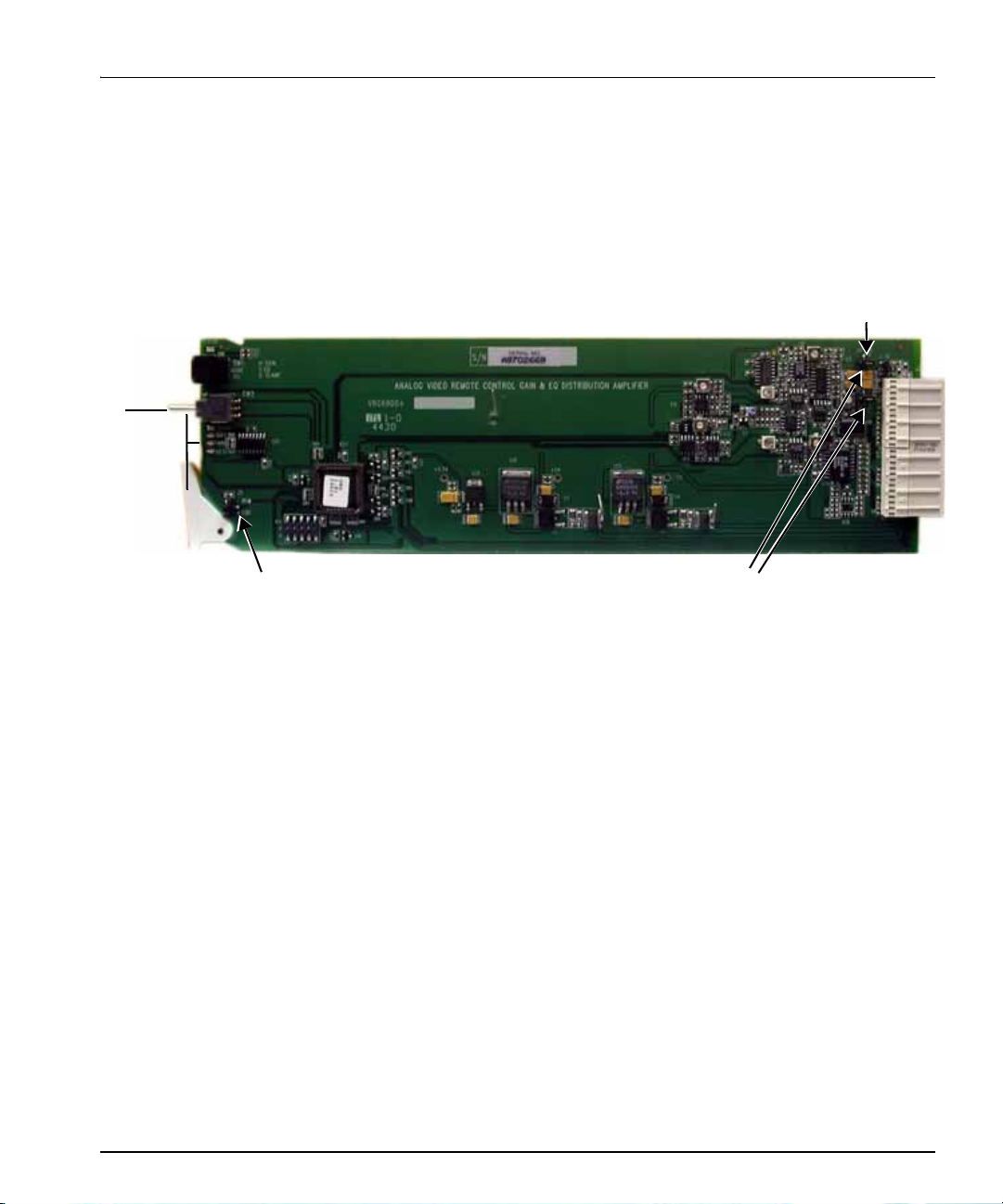
Front Module
Figure 1-1 shows the VRG6800+front module, and the location of
LEDs and jumpers.
Figure 1-1. Front Module
Control mode Input coupling mode
Signal
Soft clamp
Hard clamp
No clamp
Input termination mode
LEDs
4 VRG6800+Installation and Operation Manual
Preliminary—Contents are proprietary and confidential. Do not photocopy or distribute.
Chapter 1: Introduction
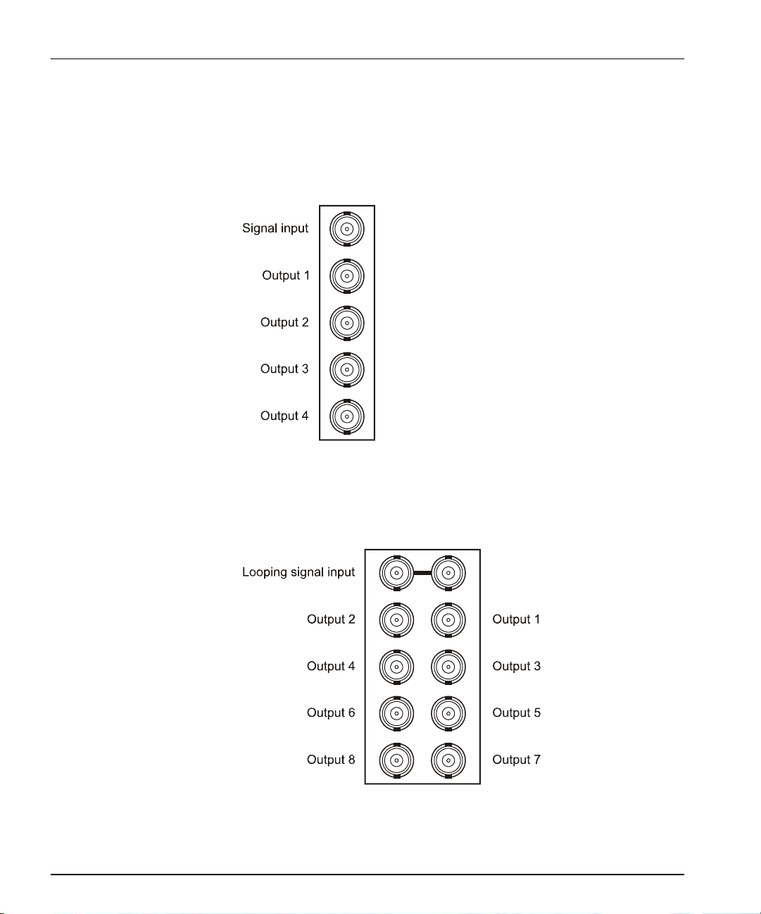
Back Modules
FR6802+Frame Back Modules
Figure 1-2 shows the single-width back module used by the VRG6800+
when installed in an FR6802+frame.
Figure 1-2. Single-Width Back Module for FR6802+Frames
Figure 1-3 shows the double-width back module used by the
VRG6800+when installed in an FR6802+frame.
Figure 1-3. Double-Width Back Module for FR6802+Frames

VRG6800+Installation and Operation Manual 5
Chapter 1: Introduction
Preliminary—Contents are proprietary and confidential. Do not photocopy or distribute.
Signal Input/Output Connections for FR6802+DM Frames
Figure 1-4 shows the signal input/output connections used by the
VRG6800+when installed in an FR6802+DM frame.
Figure 1-4. Signal Input/Output Connections for FR6802+DM
Frames
6800/7000 Series Frame Back Module (Overlay)
Figure 1-5 shows the double-width back module overlay used by the
VRG6800+when installed in a 6800/7000 series frame.
Figure 1-5. Back Module for 6800/7000 Series Frame
Note
In a DM frame, you can create
looping inputs by adding a
T-connector on the input
connection and changing the
input termination mode jumper
setting to external termination.
(The internal termination setting
is used for non-looping inputs.)
Note
Remote control for this 6800+
module is not available if it is
installed in a 6800/7000 series
frame.


VRG6800+Installation and Operation Manual 7
Preliminary—Contents are proprietary and confidential. Do not photocopy or distribute.
Chapter 2
Installation and Operation
Overview
This chapter describes the VRG6800+installation process, including
the following topics:
•“Installing 6800+ Modules” on page 15
•“LEDs and Alarms” on page 14
•“Making Connections” on page 15
•“Maximum 6800+ Frame Power Ratings” on page 8
•“Removing VRG6800+ Modules” on page 15
•“Required Frames and Back Connector Types” on page 15
•“Setting Modes” on page 10
•“Unpacking the Module” on page 9
See the Selenio FR6802+Frame Installation and Operation Manual
for information about installing and operating an FR6802+frame and
its components.
Caution
Before installing this product,
read the Selenio 6800+Series
Safety Instructions and Stan-
dards manual shipped with
every FR6802+Frame Installa-
tion and Operation Manual, or
downloadable from our website.
This safety manual contains
important information about the
safe installation and operation
of 6800+series products.

8 VRG6800+Installation and Operation Manual
Preliminary—Contents are proprietary and confidential. Do not photocopy or distribute.
Chapter 2: Installation and Operation
Maximum 6800+Frame Power Ratings
The power consumption for VRG6800+modules is listed on page 19.
Table 2-1 describes the maximum allowable power ratings for 6800+
frames. Note the given maximums before installing any 6800+modules
in your frame.
VRG6800+modules can be installed in both FR6802+frames and in
6000/7000 series frames.
Table 2-1. Maximum Power Ratings for 6800+Frames
6800+Frame Type
Max. Frame
Power
Dissipation
Number of
Usable Slots
Max. Power
Dissipation Per
Slot
FR6802+XF
(frame with AC power
supply)
120 W 20 6 W
FR6802+XF48
(frame with DC power
supply)
105 W 20 5.25 W
VRG6800+Installation and Operation Manual 9
Chapter 2: Installation and Operation
Preliminary—Contents are proprietary and confidential. Do not photocopy or distribute.
Unpacking the Module
Preparing the Product for Installation
Before you install the VRG6800+, perform the following:
• Check the equipment for any visible damage that may have
occurred during transit.
• Confirm receipt of all items on the packing list. See “Checking the
Packing List” for more information.
• Remove the anti-static shipping pouch, if present, and all other
packaging material.
• Retain the original packaging materials for possible re-use.
See “Unpacking/Shipping Information” on page vii for information
about returning a product for servicing.
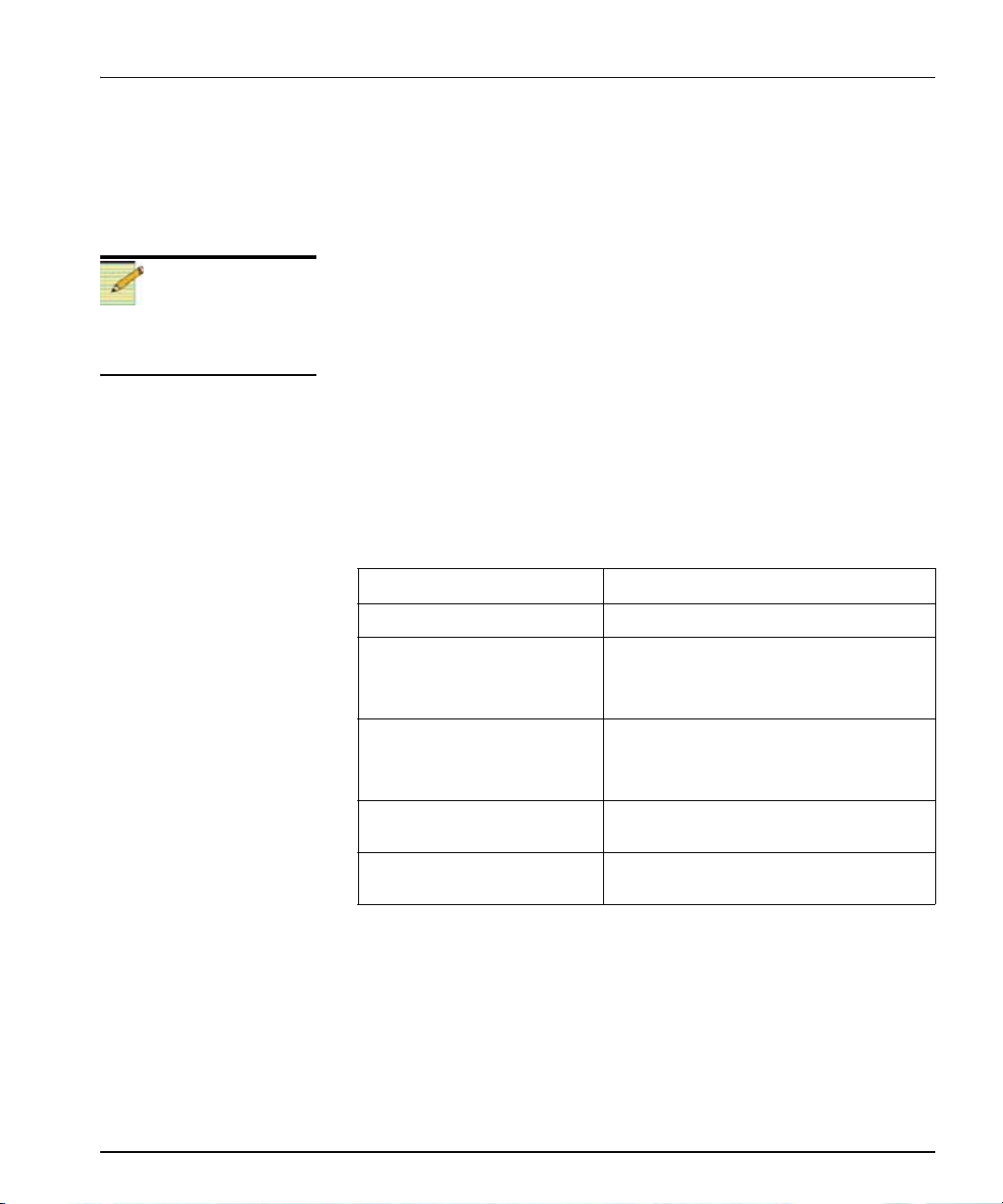
Checking the Packing List
Note
Contact your Customer Service
representative if parts are
missing or damaged.
Ordered Product Content Description
VRG6800+• One VRG6800+front module
VRG6800+S• One VRG6800+front module
• One standard single-slot back
connector
VRG6800+D• One VRG6800+front module
• One standard double-slot back
connector
VRG6800+SR • One standard single-slot back
connector
VRG6800+DR • One standard double-slot back
connector
10 VRG6800+Installation and Operation Manual
Preliminary—Contents are proprietary and confidential. Do not photocopy or distribute.
Chapter 2: Installation and Operation
Setting Modes
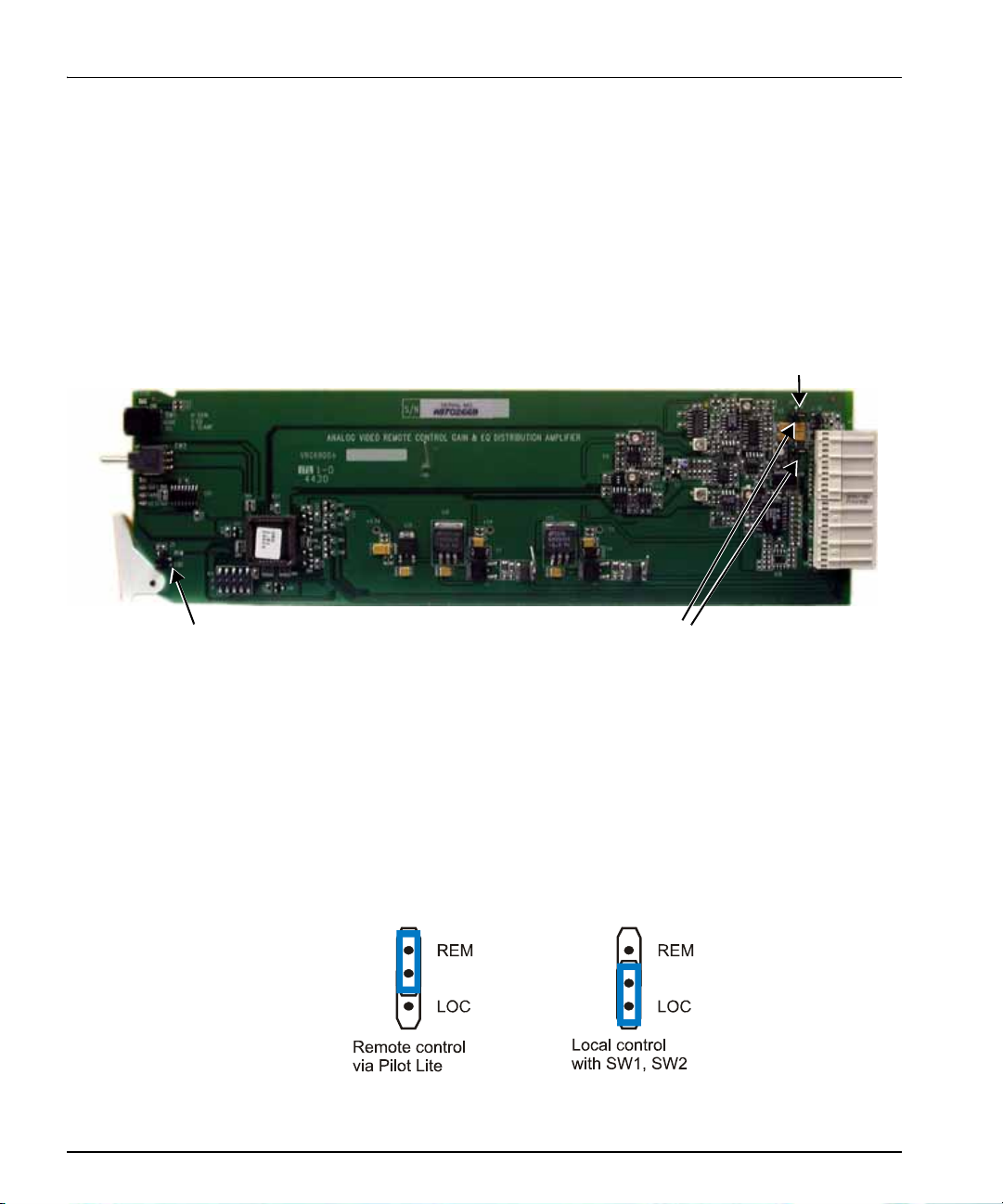
Setting Jumpers
The VRG6800+module has three standard jumpers. These jumpers are
used to set control, input coupling, and input termination modes.
Figure 2-1 shows the standard locations of the jumper blocks.
Figure 2-1. Locations of the Jumper Blocks
Setting Control Mode
Follow this procedure to set the jumper for local control mode or
remote control mode.
1. Locate the control mode jumper block on the module (see
Figure 2-1).
2. Place a jumper on the pin that corresponds to the control mode that
you want (see Figure 2-2).
Figure 2-2. Control Mode Jumper Block Settings
Control mode Input coupling mode
Input termination mode
Other manuals for Selenio 6800+
1
This manual suits for next models
1
Table of contents
Other Imagine Amplifier manuals


Popular Amplifier manuals by other brands

BLACK STAR
BLACK STAR UNITY U30 owner's manual

Better Music Builder
Better Music Builder DX-333 owner's manual

d & b audiotechnik
d & b audiotechnik XD 40D Startup manual

BOSSCO
BOSSCO Acoustic Singer Live LT owner's manual

EMPHASER
EMPHASER EA-MT1 Installation & operating manual

NASAB
NASAB BMA 30 Installation & operation manual


Audio Valve
Audio Valve RKV - Mark II user manual

Phase Technologies
Phase Technologies P350 Owners manual/install guide

Micromega
Micromega PRE owner's manual

d & b audiotechnik
d & b audiotechnik D12 Hardware manual

TRU Audio
TRU Audio AMP-440 user manual

MB QUART
MB QUART NA3-560.4 Quick start installation guide