Imagine HSE6800+ User manual

Delivering the Moment
Installaon and Operaon Manual
HSD/HSE6800+
SD/HD Serial Digital Video
Distribuon Ampliers
Edion F
175-000191-00

Publicaon Informaon
© 2014 Imagine Communicaons Corp. Proprietary and Condenal.
Imagine Communicaons considers this document and its contents to be proprietary and condenal. Except for
making a reasonable number of copies for your own internal use, you may not reproduce this publicaon, or any part
thereof, in any form, by any method, for any purpose, or in any language other than English without the wrien consent
of Imagine Communicaons. All others uses are illegal.
This publicaon is designed to assist in the use of the product as it exists on the date of publicaon of this manual, and
may not reect the product at the current me or an unknown me in the future. This publicaon does not in any way
warrant descripon accuracy or guarantee the use for the product to which it refers. Imagine Communicaons reserves
the right, without noce to make such changes in equipment, design, specicaons, components, or documentaon as
progress may warrant to improve the performance of the product.
Trademarks
6800+™, ADC™, CCS Navigator™, Channel ONE™, ChannelView™, ClipSync™, Delay™, D Series™, D Series DSX™, Deliver
the Moment™, Delivering the Moment™, FAME™, Farad™, G8™, G Scribe™, HView™, IconMaster™, IconLogo™, IconSta-
on™, IconKey™, InfoCaster™, InfoCaster Creator™, InfoCaster Manager™, InfoCaster Player™, InstantOnline™, Invenio®,
Live Update™, mCAPTURE™, Magellan™, Magellan CCS Navigator™, Magellan Q SEE™, MulService SDN™, NetPlus™,
NetVX™, NewsForce™, Nexio® G8™, Nexio AMP® ChannelView™, Nexio® Channel ONE™, Nexio® ClipSync™, Nexio®
Delay™, Nexio® Digital Turnaround Processor™, Nexio® Farad™, Nexio® G Scribe™, Nexio® IconKey™, Nexio® IconLogo™,
Nexio® IconMaster™, Nexio® IconStaon™, Nexio® InfoCaster™, Nexio® InfoCaster Creator™, Nexio® InfoCaster Manag-
er™, Nexio® InfoCaster Player™, Nexio® InfoCaster Trac™, Nexio® InstantOnline™, Nexio® mCAPTURE™, Nexio® News-
Force™, Nexio® NXIQ™, Nexio® Playlist™, Nexio® Remote™, Nexio®RTX Net™, Nexio® TitleMoon™, Nexio® TitleOne™,
Nexio® Velocity ESX™, Nexio® Velocity PRX™, Nexio® Velocity XNG™, Nexio® Volt™, OPTO+™, Panacea™, Planum™,
Playlist™, Predator II GRF™, Predator II GX™, Punctuate™, Remote™, RTX Net™, QuiC™, Q SEE™, SD STAR™, Selenio™,
Selenio 6800+™, SelenioNext™, Selenio X50™, Selenio X85™, Selenio X100™, TitleMoon™, TitleOne™, Velocity ESX™,
Velocity PRX™, Velocity XNG™, Versio™, Videotek® SD STAR™, X50™, and X85™ are trademarks of Imagine Communica-
ons or its subsidiaries.
Altude Express®, Connectus®, Enabling PersonalizedTV®, ICE® Broadcast System, ICE Illustrate®, ICE Q® algorithms, ICE-
PAC®, Imagine ICE®, Inscriber®, Inscriber® Connectus®, Invenio®, NEO®, Nexio®, Nexio AMP®, PersonalizedTV®, Router-
Works®, Videotek®, Videotek® ASI STAR®, Videotek® GEN STAR®, and Videotek® HD STAR® are registered trademarks of
Imagine Communicaons or its subsidiaries.
Microso® and Windows® are registered trademarks of Microso Corporaon. HD BNC is a trademark of Amphenol
Corporaon. Some products are manufactured under license from Dolby Laboratories. Dolby and the double D symbol
are registered trademarks of Dolby Laboratories. DTS Neural audio products are manufactured under license from DTS
Licensing Limited. DTS and the Symbol are registered trademarks & the DTS Logos are trademarks of DTS, Inc. © 2008
2010 DTS, Inc. All other trademarks and trade names are the property of their respecve companies.
Contact Informaon
Imagine Communicaons has oce locaons around the world. For locaons and contact informaon see:
hp://www.imaginecommunicaons.com/contact us/
Support Contact Informaon
For support contact informaon see:
▪Support Contacts: hp://www.imaginecommunicaons.com/services/technical support/
▪eCustomer Portal: hp://support.imaginecommunicaons.com
© 2014 Imagine Communicaons Corp. Proprietary and Condenal

Preliminary—Contents are proprietary and confidential. Do not photocopy or distribute.
HSD/HSE6800+
SD/HD Serial Digital Video Distribution
Amplifiers
Installation and Operation Manual
Edition F
January 2010


v
Copyright © 2003, 2005-2006, 2010, Harris Corporation
Contents
Preface
Manual Information ..........................................................................................vii
Revision History ..........................................................................................vii
Writing Conventions ................................................................................. viii
Obtaining Documents ............................................................................... viii
Unpacking/Shipping Information ........................................................................ix
Safety Standards and Compliances ......................................................................x
Safety Terms and Symbols ............................................................................x
Restriction on Hazardous Substances (RoHS) Directive ..................................x
Waste from Electrical and Electronic Equipment
(WEEE) Directive ..........................................................................................xi
Introduction
Product Description ............................................................................................ 2
Typical Broadcast and Production Applications ............................................ 2
Main Features ............................................................................................. 2
Module Descriptions .......................................................................................... 3
Front Module .............................................................................................. 3
Back Module ............................................................................................... 5
Signal Flow ........................................................................................................ 7
Installation
Maximum 6800+Frame Power Ratings ............................................................ 10
Unpacking the Module .................................................................................... 11
Checking the Packing List .......................................................................... 11
Setting HSD6800+Jumpers .............................................................................. 12
Setting HSE6800+Jumpers .............................................................................. 13
Installing 6800+Modules ................................................................................. 14
Installing HSD/HSE6800+Modules ............................................................. 14
Removing HSD/HSE6800+Modules ........................................................... 14
Making Connections......................................................................................... 14

Contents
vi
Copyright © 2003, 2005-2006, 2010, Harris Corporation
Operation
Understanding Jumper Controls ....................................................................... 16
Local Control ............................................................................................. 16
Remote Control ......................................................................................... 18
Understanding Parameter Types ....................................................................... 19
Adjustable Parameters ............................................................................... 19
Read-Only Parameters ............................................................................... 19
Operating Notes ............................................................................................... 19
Setting Locally Accessible Parameters ............................................................... 20
Setting Remotely Controlled Parameters .......................................................... 21
Changing Parameter Settings ........................................................................... 22
Recalling Default Parameter Settings ......................................................... 22
Reading Software and Hardware Versions ................................................. 22
LEDs and Alarms .............................................................................................. 23
Alarms ...................................................................................................... 23
Module Status LED .................................................................................... 23
Other LED Descriptions .............................................................................. 23
Specifications
Inputs .............................................................................................................. 26
Outputs ............................................................................................................ 26
Power Consumption ........................................................................................ 27
Propagation Delay............................................................................................. 27
Temperature .................................................................................................... 27
Start-Up Time .................................................................................................. 27
Index
Keywords ......................................................................................................... 29

vii
Copyright © 2003, 2005-2006, 2010, Harris Corporation
Preface
This manual details features, installation and operational procedures, and
specifications of the HSD/HSE6800+SD/HD serial digital video distribution
amplifiers.
Manual
Information
This manual is written for engineers, technicians and operators responsible for the
installation, setup, and/or operation of the HSD/HSE6800+SD/HD serial digital
video distribution amplifiers.
Revision History Table P-1 Manual Revision History
Edition Date Revision History
A November 2003 Initial release
B December 2003 Corrected Power specifications
Updated Remotely Controlled
Parameters table
Clarified input and output Return Loss
specifications
C August 2005 Added information concerning
maximum 6800+frame power ratings
Added index
D January 2006 Updated FR6802+back connector
illustrations
Moved “Troubleshooting” section to
FR6802+Frame Installation and
Operation Manual
E September 2006 Updated information concerning
jumper settings
F January 2010 Removed reference to input
termination jumper

Preface
viii
Copyright © 2003, 2005-2006, 2010, Harris Corporation
Writing
Conventions
To enhance your understanding, the authors of this manual have adhered to the
following text conventions:
Obtaining
Documents
Technical documents can be viewed or downloaded from our website.
Alternatively, contact your Customer Service representative to request a document.
Table P-2 Manual Style and Writing Conventions
Term or
Convention Description
Bold Indicates dialog boxes, property sheets, fields,
buttons, check boxes, list boxes, combo boxes,
menus, submenus, windows, lists, and selection
names.
Italics Indicates email addresses, the names of books or
publications, and the first instances of new terms and
specialized words that need emphasis.
CAPS Indicates a specific key on the keyboard, such as
ENTER, TAB, CTRL, ALT, or DELETE.
Code Indicates variables or command-line entries, such as a
DOS entry or something you type into a field.
> Indicates the direction of navigation through a
hierarchy of menus and windows.
hyperlink Indicates a jump to another location within the
electronic document or elsewhere
Internet
address
Indicates a jump to a Web site or URL
NOTE:Indicates important information that helps to avoid
and troubleshoot problems.

HSD/HSE6800+
Installation and Operation Manual ix
Copyright © 2003, 2005-2006, 2010, Harris Corporation
Unpacking/
Shipping
Information
This product was carefully inspected, tested, and calibrated before shipment to
ensure years of stable and trouble free service.
1Check equipment for any visible damage that may have occurred during
transit.
2Confirm that you have received all items listed on the packing list.
3Contact your dealer if any item on the packing list is missing.
4Contact the carrier if any item is damaged.
5Remove all packaging material from the product and its associated
components before you install the unit.
Keep at least one set of original packaging, in the event that you need to return a
product for servicing. If the original packaging is not available, you can supply your
own packaging as long as it meets the following criteria:
Withstands the weight of the product
Holds the product rigid within the packaging
Leaves at least two inches of space between the product and the container
Protects the corners of the product
Ship products back to us for servicing prepaid and, if possible, in the original
packaging material. If the product is still within the warranty period, we will return
the product prepaid after servicing.
Preface
x
Copyright © 2003, 2005-2006, 2010, Harris Corporation
Safety
Standards
and
Compliances
See the 6800+Safety Instructions and Standards Manual to find the safety
standards and compliances for this 6800+series product. A safety manual is
shipped with every FR6802+Frame Installation and Operation Manual and
can be downloaded from our website. Alternatively, contact your Customer Service
representative for a copy of this safety manual.
Safety Terms and
Symbols
This product manual uses the following safety terms and symbols to identify
certain conditions or practices. See the 6800+Safety Instructions and
Standards Manual for more information.
Restriction on
Hazardous
Substances
(RoHS) Directive
Directive 2002/95/EC — commonly known as the European Union (EU) Restriction
on Hazardous Substances (RoHS) — sets limits on the use of certain substances
found in electrical and electronic equipment. The intent of this legislation is to
reduce the amount of hazardous chemicals that may leach out of landfill sites or
otherwise contaminate the environment during end-of-life recycling. The Directive,
which took effect on July 1, 2006, refers to the following hazardous substances:
Lead (Pb)
Mercury (Hg)
Cadmium (Cd)
Hexavalent Chromium (Cr-V1)
Polybrominated Biphenyls (PBB)
Polybrominated Diphenyl Ethers (PBDE)
In accordance with this EU Directive, products sold in the European Union will be
fully RoHS-compliant and “lead-free.” Spare parts supplied for the repair and
upgrade of equipment sold before July 1, 2006 are exempt from the legislation.
Equipment that complies with the EU directive will be marked with a
RoHS-compliant symbol, as shown in Figure P-1.
Table P-3 Safety Terms and Symbols
Symbol Description
WARNING: Identifies conditions or practices that can result in
personal injury or loss of life — high voltage is present.
Uninsulated dangerous voltage within the product’s enclosure
may be sufficient to constitute a risk of electric shock to
persons.
CAUTION: Identifies conditions or practices that can result in
damage to the equipment or other property. Important
operating and maintenance (servicing) instructions are
included in the literature accompanying the product.

HSD/HSE6800+
Installation and Operation Manual xi
Copyright © 2003, 2005-2006, 2010, Harris Corporation
Figure P-1 RoHS Compliance Symbol
Waste from
Electrical and
Electronic
Equipment
(WEEE) Directive
The European Union (EU) Directive 2002/96/EC on Waste from Electrical and
Electronic Equipment (WEEE) deals with the collection, treatment, recovery, and
recycling of electrical and electronic waste products. The objective of the WEEE
Directive is to assign the responsibility for the disposal of associated hazardous
waste to either the producers or users of these products. As of August 13, 2005,
producers or users are required to recycle electrical and electronic equipment at
end of its useful life, and must not dispose of the equipment in landfills or by using
other unapproved methods. (Some EU member states may have different
deadlines.)
In accordance with this EU Directive, companies selling electric or electronic devices
in the EU will affix labels indicating that such products must be properly recycled.
Contact your local Sales representative for information on returning these products
for recycling. Equipment that complies with the EU directive will be marked with a
WEEE-compliant symbol, as shown in Figure P-2.
Figure P-2 WEEE Compliance Symbol

Preface
xii
Copyright © 2003, 2005-2006, 2010, Harris Corporation

1
Copyright © 2003, 2005-2006, 2010, Harris Corporation
1Introduction
The HSD/HSE6800+are SD/HD serial digital video distribution amplifiers. The
following topics are described in this chapter:
Main Features on page 2
Module Descriptions on page 3
Product Description on page 2
Signal Flow on page 7

Chapter 1
Introduction
2
Copyright © 2003, 2005-2006, 2010, Harris Corporation
Product
Description
HSD6800+and HSE6800+are SD/HD serial digital video distribution amplifiers in
the 6800+family:
The HSD6800+is an SD/HD serial digital video distribution amplifier with cable
equalizing.
The HSE6800+is an SD/HD serial digital video distribution amplifier with cable
equalizing and reclocking.
Both distribution amplifiers feature high video performance, low cost, remote
control, and diagnostic capability in our control system.
You can set up, control, and monitor the HSD/HSE6800+either locally via a
card-edge jumper or remotely on a PC. For remote control, you can use either a
serial RS-232 or optional ICE6800+Ethernet connection.
Typical Broadcast
and Production
Applications
The HSD/HSE6800+distribution amplifier can be used in broadcast, cable,
production, educational, and auditorium applications where a low cost method of
distributing serial digital video signals is required.
Main Features Other HSD/HSE6800+features include the following:
One input, eight outputs for the dual slot back module; or one input, four
outputs for the single slot back module
Input signal presence detect
Automatic cable equalization
Alarm output
Automatic/manual reclock rate setting at 143 Mb/s, 177 Mb/s (manual only),
270 Mb/s SDI and ASI, 360 Mb/s, 540 Mb/s; and 1.485 Gb/s (HSE6800+only)
Reclocking status report (HSE6800+only)
Automatic/enforced bypass (HSE6800+only)

HSD/HSE6800+
Installation and Operation Manual
3
Copyright © 2003, 2005-2006, 2010, Harris Corporation
Module
Descriptions
Front Module Figure 1-1 is a generic top-front view of a typical HSD6800+front module. See
Figure 2-1 on page 12 for jumper locations.
Figure 1-1. Typical HSD6800+Front Module
Figure 1-2 is a generic top-front view of a typical HSE6800+front module. See
Figure 2-3 on page 13 for jumper locations.
Figure 1-2. Typical HSE6800+Front Module

Chapter 1
Introduction
4
Copyright © 2003, 2005-2006, 2010, Harris Corporation
LEDs, Switches, and Jumpers
Each 6800+module has a number of LEDs assigned to indicated varying states/
functions. Table 1-1 briefly describes generic 6800+LEDs, switches, and jumpers.
For HSD/HSE6800+modules, module-specific functions are listed in Table 3-5 on
page 23. See Chapter 3,Operation for more information on specific HSD/
HSE6800+module controls, LEDs, and jumpers.
Table 1-1 Generic 6800+Module Features
Feature Description
Module status
LEDs
Various color and lighting combinations of these LEDs indicate
the module state. See Table 3-4 on page 23 for more
information.
Control LEDs Various lighting combinations of these control LEDs
(sometimes referred to as “Bank Select LEDs”) indicate the
currently selected bank. (This item not available on the HSD/
HSE6800+)
Monitoring
LEDs
Each 6800+module has a number of LEDs assigned to
indicate varying states/functions.
Local/remote
control jumper
Local: Locks out external control panels and allows
card-edge control only; limits the functionality of remote
software applications to monitoring
Remote: Allows remote or local (card-edge) configuration,
operation, and monitoring of the HSD/HSE6800+
HSD/HSE6800+
Installation and Operation Manual
5
Copyright © 2003, 2005-2006, 2010, Harris Corporation
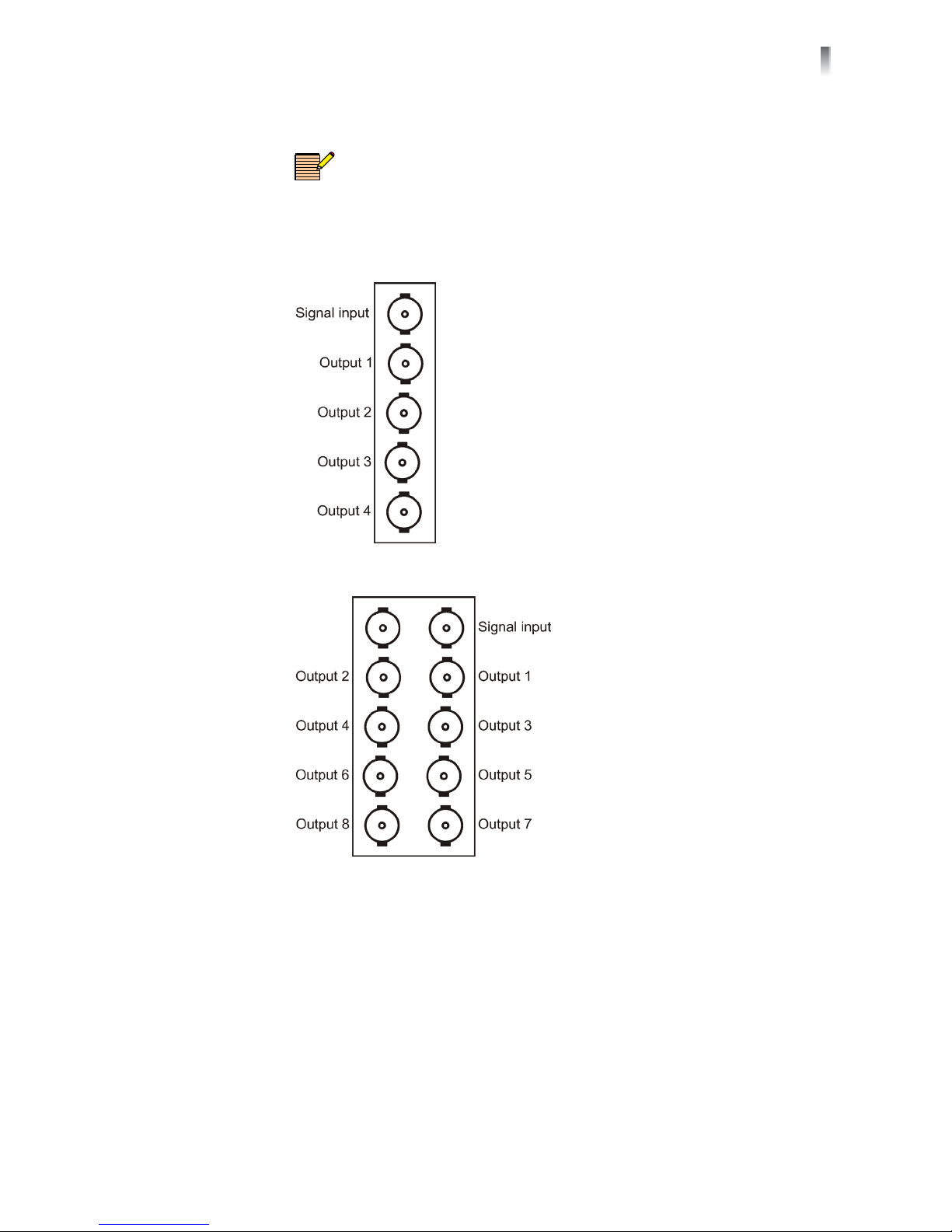
Back Module FR6802+Frame Back Module
NOTE: The HSD/HSE6800+cannot be installed in a 6800/7000 series
frame.
Figure 1-3 shows the single-width back connector and Figure 1-4 shows the
double-slot back connector used by the HSD/HSE6800+when installed in an
FR6802+frame.
Figure 1-3 Single-Width Back Connectors for FR6802+Frame
Figure 1-4 Double-Width Back Connectors for FR6802+Frame

Chapter 1
Introduction
6
Copyright © 2003, 2005-2006, 2010, Harris Corporation
Signal Input/Output Connections for FR6802+DM Frames
Figure 1-5 shows the signal input/output connections used by the HSD/HSE6800+
when installed in an FR6802+DM frame.
Figure 1-5 Double-Slot Back Module for FR6802+DM Frames
HSD/HSE6800+
Installation and Operation Manual
7
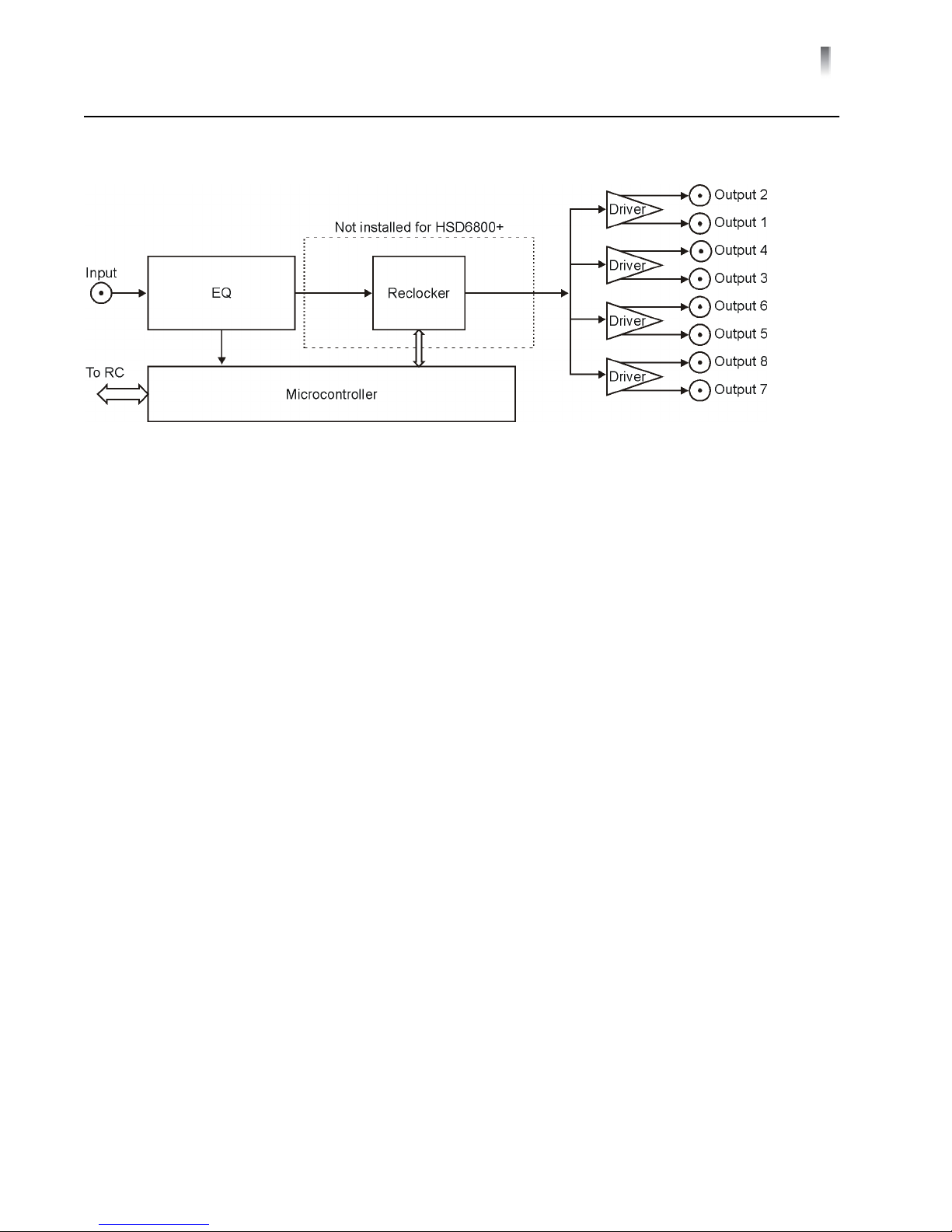
Copyright © 2003, 2005-2006, 2010, Harris Corporation
Signal Flow
Figure 1-6. HSD/HSE6800+Signal Flow Diagram

Chapter 1
Introduction
8
Copyright © 2003, 2005-2006, 2010, Harris Corporation
This manual suits for next models
1
Table of contents
Other Imagine Amplifier manuals


