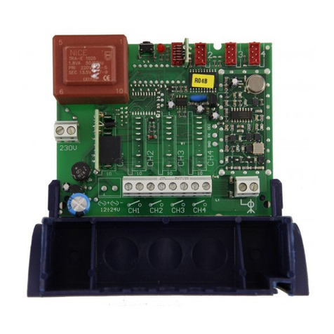
Imagine XTR-WRC-24 Series User manual

User Manual: XTR-WRC Series Wireless Control System © 2019 Imagine Instruments LLC
Page 1
User Manual
Series: XTR-WRC-24, XTR-WRC-900
Wireless Remote-Control Switch Transmitter/Relay
Receiver System
Imagine Instruments LLC, 4500 Williams Drive, Ste 212-318, Georgetown, TX 78633
Web: www.ImagineInstruments.com, Phone: (512) 778-6850, Email: info@imagineinstruments.com

User Manual: XTR-WRC Series Wireless Control System © 2019 Imagine Instruments LLC
Page 2
Table of Contents
Page
Section1 Before You Begin Using Your Unit
1.1 Symbols & Safety Information ………………………………………………….………………………………. ….. 4
1.2 Conditions of Use ……………………………………………………………………………………………….…….. 5
1.3 Unpacking ……………………………………………………………………………..…………….…………………. 5
Section 2 Introduction
2.1 Product Description ……………………………………………………………………………………………...……..5
2.2 Available Models & Options ……………………………………………………………………………………….…. 5
Section 3 Specifications
3.1 Specifications ……………………………………………………….……………...………………….……….……… 6
3.2 Environmental Operating Conditions……………………………………………..…………….……….……..……. 7
3.3 Regulatory Approvals & Export Compliance ………………………………..………………………..…………... 7
Section 4 Installation
4.1 General Guidance ……………………………….…………..…………………..……………………….…………… 8
4.2 Mounting and Area Environment ………………………………………………………..……………..……………. 8
4.3 Antenna Installation, Positioning and Connection …………………………………………….............................. 8
4.4 Antenna Cables ………………………………………………………………………............................................ 10
Section 5 Setup & Wiring
5.1 Powering Your Unit …………………………………………………………………………….………......………… 11
Section 6 General Operation
6.1 Basic System Operation & Factory Settings ………………………………….…………………………………… 12
6.2 Status LED ……………………………………………………………….…………………..…………………..…… 12
6.3 Bench Test Prior to Field Installation …………………………………………………………………………..…… 13
6.4 Enclosure Dimensions & Mounting ……………………………………………………………………………….… 14
Section 7 Connecting Switches & Control Outputs
7.1 Connecting Switch Inputs …………………………………………………………………………………….…...…. 15
7.2 Connecting Relay Outputs …………..…………………………………………………………………….…….…… 16
Section 8 Maintenance
8.1 Maintenance …………………………………………………………………………………….…….……..………… 16
Section 9 Warranty & Liability
9.1 Warranty/Product Returns ………………………………………………………………….…………….…………… 17
9.2 Limitation of Liability …………………………………………………………………………………………………… 17
Section 10 Service
10.1 Repair & Service ………………………………………………………………………………………………….…… 18
10.2 Contact Information …………………………………………………...…………………...………………..………… 18

User Manual: XTR-WRC Series Wireless Control System © 2019 Imagine Instruments LLC
Page 3
List of Figures
Page
Figure 1. The Fresnel Zone …………………………..………………...……………………………………..…… 9
Figure 2. Vertical Antenna Example ………………………………….….…………………………..…………… 10
Figure 3. Horizontal Antenna Example ………………………………….…………………………..….………… 11
Figure 4. Power Supply Connection ………………………………….….…………………………..…………… 12
Figure 5. Status LED……………………………………………. ……………….….………………..……….…… 13
Figure 6. Enclosure Dimensions (Rear View) …………………………..………………..……………………… 14
Figure 7. Enclosure Mounting Tabs ………………..…………………..…………………………….…………… 15
Figure 8. Transmitter Switch Connection ………………..……………………….………………….…………… 15
Figure 9. Receiver Output Relay Connection ..………………..…………………………………………….…… 15

User Manual: XTR-WRC Series Wireless Control System © 2019 Imagine Instruments LLC
Page 4
Section1 Before You Install and Use Your Equipment
1.1 Symbols & Safety Information
Listed below are the International Symbols used on the product, or in this manual.
Danger: Electric Shock Hazard
Warning: Refer to Documentation and Users Guide
General Safety Guidelines
•Follow all safety guidelines outlined in this guide and/or marked on the unit.
•Never install or operate this product outside the specifications listed in this guide.
•Never install and operate in flammable or explosive environments.
•Install your unit in a location that is out of the reach of unauthorized personnel.
•Always install additional disconnect and safety devices to provided added protection.
•Never operate this product outside the environmental limits specified in this guide.
Electrical Safety Guidelines
•Never attempt maintenance or service while power is connected.
•Installation and all wiring should be done by a trained professional.
Note: Personnel entrusted with installation, setup and operation of this product must be suitably qualified and
trained. The required knowledge and experience can be gained via training courses and appropriate on-the-job
instruction. Personnel should have this document available to them at all times when working with this product.
RF Safety Guidelines
•Only operate this product with the antenna provided or optional antennas listed in this guide.
•Never install and operate this product where there will always be people closer than 20 cm.
•Never operate multiple units within 20 cm or less from each other.
•Never operate other RF transmitters of the same frequency within 20 cm or less of this product.
1.2 Condition of Use
Imagine Instruments LLC products are not designed, intended or authorized for use in medical applications,
applications intended to sustain or support life, in any nuclear facilities or any other application where the
failure of the product could create a situation where catastrophic property damage, personal injury or death
may occur. In the event that the Customer purchases or uses any Imagine Instruments LLC products for any
such unintended or unauthorized application, the Customer shall indemnify and hold harmless Imagine
Instruments LLC and its officers, directors, employees, agents, affiliates, successors and assigns against all
claims, costs, damages and expenses (including reasonable attorneys' and expert witness' fees) arising out of
or in connection with, directly or indirectly, any claim for property damage, personal injury or death associated
with such unintended or unauthorized use, even if such claim alleges that Imagine Instruments LLC was
negligent regarding the design or manufacture of the subject product.

User Manual: XTR-WRC Series Wireless Control System © 2019 Imagine Instruments LLC
Page 5
1.3 Unpacking
Unpack your product carefully and inspect for any shipping damage. Notify the carrier immediately if you find
damage.
The following items are included with your system:
•Two Antennas
•Transmitter / Receiver Set
•This User’s Guide
Section 2 Introduction
2.1 Product Description
The XTR-WRC Series Wireless Remote-Control System allows for remotely activating equipment from a
distance of up to 1 mile for XTR-WRC -24 or up to 6 miles for XTR-WRC -900 using license free wireless radio
communication. Units are equipped with contact closure inputs that are used to control open-collector outputs.
Models are available with 1 or 2 control lines. The control inputs are activated with any type, non-powered dry-
contact switch or relay contacts in an automated control system (such as a PLC). The provided control relay
outputs are SPDT type and operate with DC a maximum load capacity of 10 Amps max.
2 2 Available Models & Options
Model Number Description Control Lines
XTR-WRC-24-1 2 4 GHz Wireless Control Transmitter/Receiver Set 1
XTR-WRC-900-1 900 MHz Wireless Control Transmitter/Receiver Set 1
XTR-WRC-24-2 2 4 GHz Wireless Control Transmitter/Receiver Set 2
XTR-WRC-900-2 900 MHz Wireless Control Transmitter/Receiver Set 2
Optional Items
Model Number Description
DRWC-24-LRANT 2 4 GHz Long Distance Antenna Set
DRWC-900-LRANT 900 MHz Long Distance Antenna Set

User Manual: XTR-WRC Series Wireless Control System © 2019 Imagine Instruments LLC
Page 6
Section 3 Specifications
3 1 Specifications
Models: XTR-WRC-24-1, XTR-WRC-24-2
Radio Frequency: ISM 2.4 GHz
RF Power Output: 79mW
RF Data Rate: 250 kbps
Regulatory: FCC Part 15 Compliance (No license required)
Control Lines: (see model chart)
Receive Sensitivity: -103 dBm
Antenna Connection: RP-SMA
Antennas: 5dbi, Omni-directional (Included)
Transmit/Receive Distance (with included antenna set)
US/CA Model: Indoor/Urban 100ft, Outdoor Line-of-site 600ft
Transmit/Receive Distance (with optional antenna set)
US/CA Model: Indoor/Urban 300ft, Outdoor Line-of-site 1 Mile
Transmitter/Receiver Code Matching: Factory set
Wire Connection: Terminal Blocks, 14-24AWG
Switch Input: Non-powered, Dry-contact only.
Control Output: Relay SPDT 10A 120V AC Max
Operating Temperature: -22 to 113 ºF (-30 to 45 ºC)
Operating Power: 12 - 14V DC @ 2W max
Enclosures: NEMA 4X, Powder Coated Aluminum (4.5 x 4.5 x 2.8”)
Models: XTR-WRC-900-1, XTR-WRC-900-2
Radio Frequency Band: 902 MHz to 928 MHz
RF Power Output: 250mW
RF Data Rate: 10 kbps
Regulatory: FCC Part 15 Compliance (No license required)
Control Lines: See model chart
Receive Sensitivity: -110 dBm
Antenna Connection: RP-SMA
Antennas: 7dbi, Omni-directional (Included)
Transmit/Receive Distance (with included antenna set) Indoor/Urban 1000ft, Outdoor Line-of-site 3
miles, (with optional antenna set) Indoor/Urban 1600ft, Outdoor Line-of-site 6 miles.
Transmitter/Receiver Code Matching: Factory set
Wire Connection: Terminal Blocks, 14-24AWG
Switch Input: Non-powered, Dry-contact only.
Control Output: Relay SPDT 10A 120V AC Max
Operating Temperature: -22 to 113 ºF (-30 to 45 ºC)
Operating Power: 12 - 14V DC @ 3W max
Enclosures: NEMA 4X, Powder Coated Aluminum (4.5 x 4.5 x 2.8”)

User Manual: XTR-WRC Series Wireless Control System © 2019 Imagine Instruments LLC
Page 7
3 2 Environmental Operating Conditions
This product has been designed to provide performance and durability over its lifetime To keep this
product working correctly it should be handled with care and only operated within the following
recommended environmental operating conditions
•An ambient operating temperature range of -10 to130 ºF (-23 to 54 ºC)
•A relative humidity of 0-90% Non-condensing
3 3 Regulatory Approvals, Location Use & Export Compliance
REGULATORY APPROVALS
Models: WIDXL-24
FCC(USA) - MCQ-XBEE3
IC (Canada) - 1846A-XBEE3
Models: WIDXL-900
FCC(USA) - MCQ-XB900HP
IC (Canada) - 1846A-XB900HP
The enclosed device complies with Part 15 of the FCC Rules Operation is subject to the following two
conditions: (1 ) this device may not cause harmful interference and (2 ) this device must accept any
interference received, including interference that may cause undesired operation
Statement of CE Conformity
Imagine Instruments LLC is committed to compliance with the laws and regulations in each country
into which we ship our products Please contact us to learn the current status of CE compliance for
this product
Location Use
Standard models of this product are limited to the sale and use in USA and Canada only Additional
models are available for use in Europe (EU), Australia, New Zealand and Japan Please contact us for
model number and availability
Export Compliance Policy
Customer shall not, directly or indirectly, export, re-export, transfer, furnish or ship products in violation
of any applicable export control laws or regulations of any country having jurisdiction over the
products, including any and all US law or US Government export controls Customer agrees, at
Customer’s own expense, to comply with all applicable export laws and will, in accordance with the
indemnification provisions of these Terms and Conditions, indemnify, defend and hold Imagine
Instruments LLC, Its officers, owners, agents and employees harmless from any claim against Imagine
Instruments LLC due to Customer’s violation or alleged violation of any export laws

User Manual: XTR-WRC Series Wireless Control System © 2019 Imagine Instruments LLC
Page 8
Section 4 Installation
4 1 General Guidance
Your wireless control system must be installed and maintained as described in this guide to ensure
reliable safe operation Confirm the voltage and current draw of your connected load to the control
output is consistent with the design specifications of this product and your application will not exceed
the maximum load capacity listed
4 2 Mounting and Area Environment
This product has been designed for indoor or protected outdoor use Ensure that the unit has
sufficient area for proper antenna positioning See below
************************* CAUTION *******************************
Never operate this product in areas where flammable liquids, gases or an other flammable
materials are or might be present.
4 3 Antenna Installation, Positioning and Connection
Proper antenna installation and positioning is important and will allow you to achieve maximum
performance and distance between your transmitter and receiver unit This will reduce the possibility
of a lost connection during operation
Antenna Basics
When installing your transmitter and receiver it is important to install both units in such a way as to
optimize the position of both antennas within what’s known as the “Fresnel Zone” A Fresnel
Zone can be thought of as a football shaped invisible tunnel between two antennas that provides an
optimum path for the RF signals between your transmitter and receiver
Figur 1. Th “Fr sn l Zon ”

User Manual: XTR-WRC Series Wireless Control System © 2019 Imagine Instruments LLC
Page 9
In order to achieve maximum distance, the path in which the RF signals travel must be free of all
obstructions Obstacles in the path will decrease the transmit/receive distance Also, if the antennas
are mounted too low to the ground, most of the Fresnel zone ends up being obstructed by the earth
resulting in significant reduction in transmit/receive distance Your antennas should be mounted as
high off of the ground as possible
NOTE:
It is important to understand that your application environment may change over time due to new
equipment, buildings or another RF device being installed There can also be change within your
building such as new construction, etc If new obstacles are added between your switch transmitter
and relay receiver you may need to move and reposition your antennas
Connecting Your Antennas
Your control system has been shipped to you with standard antennas In some difficult installations
you may wish to place a remote antenna farther away to maximize transmission range to the
receiver A remote antenna kit option can be ordered that include an antenna extension cable and
antenna mounting bracket Please note that very long antenna extension cables will always add loss
to the signal strength The longer the cable the more signal will be lost over the cable Because of this
the length of the cable should be kept as short as possible Use of any other antenna then what’s
supplied with your system or what’s available as an option may void FCC and IC regulatory
compliance
Antenna Placement (Standard Included Omni Antennas)
Vertical Antenna Placement
If the antenna for one of your units is mounted in a vertical position you should mount the antenna of
the opposing unit in the same polarization
Figure 2 Vertical Antenna Example

User Manual: XTR-WRC Series Wireless Control System © 2019 Imagine Instruments LLC
Page 10
Horizontal Antenna Placement
If the antenna for one of your units is mounted in a horizontal position you should mount the antenna
of the opposing unit in the same polarization
Antenna Placement (Optional Long-Distance Yagi Antennas)
Horizontal Antenna Placement
The optional long-distance Yagi antennas must be mounted in the horizontal position as shown in the
picture below Antennas should be mounted pointed at each other
Figur 3. Horizontal Ant nna Exampl
4 4 Antenna Cables
In some Wireless Control System installations antenna extension cables are needed between the
transmitter or receiver and the antennas being used This is mainly because the antennas need to be
mounted higher off the ground, or out of the way of physical obstructions to obtain a clearer line-of-
site for the RF signal path
The one drawback in using antenna extension cables is the resulting signal loss Signal loss through a
length of coaxial cable is primarily a function of two things: Length and Frequency The longer the
length of a piece of coaxial cable, the more signal is lost The higher the frequency of the signal
passing through the coaxial cable, the higher the loss over a given length Coaxial cable loss is
normally specified in dB loss per foot of cable
The cable between the Transmitter / Receiver box and antenna should never exceed 20 ft

User Manual: XTR-WRC Series Wireless Control System © 2019 Imagine Instruments LLC
Page 11
Section 5 Setup & Wiring
5 1 Powering Your Unit
For proper operation and safety your system must always be earth grounded
WARNING: Electrical Shock Hazard
All wiring should be done by a qualified suitably trained person only
CAUTION: Ensure all control output connections are well insulated
Note: Fusing is recommended in series with control outputs
Powering Supply Wiring
Both the Transmitter and Receiver operate on 12-14V DC A power supply with a 3W or higher
operating capacity is sufficient Power to operate both the transmitter and receiver are connected
to Terminal 1 (+) and Terminal 2 (-) See below example
Figur 4. Pow r Supply Conn ction
Battery Power with Solar Charging Operation
Your switch Transmitter board can also be powered with a 12V DC rechargeable deep-cycle
battery, solar panel and solar charge controller The solar panel and charge controller will re-charge
the battery each sunny day This setup will provide uninterrupted power to your switch transmitter

User Manual: XTR-WRC Series Wireless Control System © 2019 Imagine Instruments LLC
Page 12
Section 6 – General Operation & Mounting
6 1
Basic System Operation & Factory Settings
This Wireless Remote-Control System allows for remotely activating equipment using license free radio
communication Contact closure inputs on the Transmitter are used to control relay outputs on the
opposing unit within the system Inputs are activated with dry-contact manual switches or connected
to a PLC for automated control
Factory Settings
Units are sold and shipped as a “Matched Pair” Factory code setting ensures matched pair units only
communicates with each other Multiple matched pair systems can be used within the same area
without interfering with each other Each unit receives a factory code that is printed on the product
label
6 2 Status LED
On the front of both the transmitter and receiver there is a yellow “Status” light (LED) This status light
will blink on and off continuously when the unit is powered correctly, and the unit is functioning
normally The light does not indicate communication between units If the light is not blinking
continuously when the unit is powered there is something wrong with the unit and it will not transmit or
receive signals
Figur 5. Status LED

User Manual: XTR-WRC Series Wireless Control System © 2019 Imagine Instruments LLC
Page 13
6 3 Bench Test Prior to Field Installation
Even though your system has been factory tested prior to shipping we recommend that you bench
test the system yourself before you permanently install the units in the field Bench testing the system
will allow you to confirm that the system is working and let you become familiar with how the system
works This will help you understand what the problem might be if you fail to get the relay to switch on
and off after your field install the system
Here is the recommended bench test procedure…
1 Place the Transmitter and Receiver on a bench or table about 4 feet apart from each other
2 Connect power to both units shown in this manual (12V DC)
3 Observe that the yellow “Status” light on both units are blinking on and off continuously
4 Short the switch input connection on the Transmitter (a short piece of wire can be used)
5 Observe that when you apply and then remove the switch input shorting wire that the relay in
the Receiver unit is switching on and off accordingly You should be able to hear the relay
clicking as it energizes and then releases You can also connect a Ohm meter across the relay
normally open contacts and see that the connection changes state
Now that you have bench test the system and have seen that it works you can move on to your field
installation
6 4 Recommended Field Installation Procedure
Receiver Installation
When field installing your system, we recommend that you permanently install the control receiver
first Make sure to follow all the recommendations and guidance outlined in the Antenna installation
section of this user guide Antennas should be mounted in the correct polarization and as high off the
ground as possible
Transmitter Installation
When field installing the Transmitter, we recommend that you temporarily make the Transmitter a
portable unit be connecting a small 12V DC battery to the unit and use a piece of shorting wire to
simulate the switch you will connect to the input By doing this you can move the Transmitter and
antenna around until you get a good solid signal connection between the Transmitter and Receiver
We recommend that you have an additional person during the installation so they can monitor the
Receiver unit and let you know when the relay is turning on and off as you try shorting the switch
input This 2-person operation (communicating by Cell Phone) is especially useful when the distance
between the Transmitter and receiver is a great distance apart After finding the optimum location
for the Transmitter and antenna they can be permanently mounted

User Manual: XTR-WRC Series Wireless Control System © 2019 Imagine Instruments LLC
Page 14
6 5 Enclosure Dimensions
Figur 6. Enclosur Dim nsions (R ar Vi w)
Enclosure Mounting
The Transmitter and Receiver enclosures are mounted with the metal ear tabs shown in the picture
below Self-tapping screws are provided to secure the ear tabs to the enclosure body
The enclosures are standard metal conduit boxes that have ½” NPT holes allowing the use of
standard conduit fittings or cable glands for wire entry and exit Hole plugs are provided to seal-off
any unused holes
Figur 7. Enclosur Mounting Tabs

User Manual: XTR-WRC Series Wireless Control System © 2019 Imagine Instruments LLC
Page 15
Section 7 – Connecting Switch Inputs & Control Outputs
7 1
Connecting Transmitter Switches
On models XTR-WRC-24 or XTR-WRC-900 there are switch inputs on only one side of the system Switch
inputs are only on what we call “the transmitter” The switch inputs connected to the transmitter must
be “dry-contact type That means you do not need to supply any type of power on the input circuit
The input is a two-wire connection that can be a simple mechanical switch, a level or flow switch, or
the contacts of a relay If you apply power to any of the switch inputs, you will damage the unit
Figure 8 Transmitter Switch Connection

User Manual: XTR-WRC Series Wireless Control System © 2019 Imagine Instruments LLC
Page 16
7 2
Connecting Output Relays
On models XTR-WRC-24 or XTR-WRC-900 there are control outputs on only one side of the system
Control outputs are only on what we call “the receiver” The control outputs are 10A SPDT
mechanical relays Connection to the relay is made by use of standard ¼” push-on disconnects
Figure 9 Output Relay Connection

User Manual: XTR-WRC Series Wireless Control System © 2019 Imagine Instruments LLC
Page 17
Section 8 Maintenance
8 1 Maintenance
This product has been designed to be maintenance free during its lifetime Periodic inspection should
take place to ensure that the following has not occurred during use:
•Ensure the unit is still mounted securely and has not become loose due to vibration
•With power removed Ensure all wiring connection are still tight and well insulated
•Ensure the unit is free of moisture, grease, dirt or any other foreign material
If the outside of this product has become soiled, it may be wiped clean with a lightly damp cloth
Allow the unit to air dry for a least 48 hours after cleaning before use Only clean the unit when
Section 9 Warranty & Liability
9 1 Warranty/Product Returns
Imagine Instruments LLC as expressed as “Company” in this document
All Product orders are subject to written acceptance by Company by a duly authorized agent of
Company This product is covered by a Limited Warranty for a period of 5 years from the date of
purchase which applies to defective Products only COMPANY EXPRESSLY DISCLAIMS ALL OTHER
WARRANTIES OF ANY KIND, WHETHER EXPRESS OR IMPLIED, INCLUDING, BUT NOT LIMITED TO, IMPLIED
WARRANTIES OF MERCHANTABILITY AND FITNESS FOR A PARTICULAR PURPOSE Company will only
accept the return of defective Products Such returns must be pre-approved by Company in writing
and an RMA (Return Material Authorization) number must be issued by Company before Company
will accept such return Return shipments not pre-approved by Company will be refused Company
will inspect pre-approved returns to determine whether they are defective, which determination by
Company is final Products must be returned in the same or equivalent container and packaging
materials in which they were originally shipped Customer retains title to any Products returned
Return freight cost is the responsibility of Customer If Company determines a Product is defective, it
may repair or replace the defective Product
9 2 Limitation of liability
COMPANY’S LIABILITY ON ANY CLAIM OF ANY KIND, INCLUDING NEGLIGENCE, FOR ANY LOSS OR DAMAGE
ARISING OUT OF, CONNECTED WITH, OR RESULTING FROM THE MANUFACTURE, SALE, DELIVERY, RESALE, REPAIR
OR USE OF ANY PRODUCTS COVERED BY OR FURNISHED HEREUNDER, SHALL IN NO CASE EXCEED THE LESSER OF
THE COST OF REPAIRING OR REPLACING PRODUCTS FAILING TO CONFORM TO THE WARRANTIES CONTAINED
HEREIN, IF ANY, OR THE PRICE OF THE PRODUCTS OR PART THEREOF WHICH GIVES RISE TO THE CLAIM IN NO
EVENT WILL COMPANY BE LIABLE FOR ANY DIRECT, INDIRECT, INCIDENTAL, SPECIAL OR CONTINGENT DAMAGES,
INCLUDING, BUT NOT LIMITED TO, DAMAGES FOR LOSS OF PROFITS, GOODWILL, USE OR OTHER INTANGIBLE LOSS
(EVEN IF COMPANY HAS BEEN ADVISED OF THE POSSIBILITY OF SUCH DAMAGES), RESULTING FROM: (I) THE USE OR
THE INABILITY TO USE PRODUCTS PURCHASED FROM COMPANY; (II) THE COST OF PROCUREMENT OF SUBSTITUTE
PRODUCTS RESULTING FROM ANY PRODUCTS PURCHASED OR OBTAINED FROM COMPANY; OR (III) ANY OTHER
MATTER RELATING TO PRODUCTS PURCHASED FROM COMPANY
Additional “Terms & Conditions” apply Please visit www imagineinstruments com to read the complete
Imagine Instruments LLC “Terms & Conditions” statement

User Manual: XTR-WRC Series Wireless Control System © 2019 Imagine Instruments LLC
Page 18
Section 10 Repair & Service
10 1 Repair / Service
An RMA (Return Merchandise Authorization) number must be obtained before the product is
returned to us Please call us to obtain an RMA number Any product received without a RMA will be
returned to the customer The cost and method of shipping the product back to us is the sole
responsibility of the customer We recommend a track-able form of shipping to guarantee your
package arrives to us If a package is sent without proof of delivery, Imagine Instruments LLC is not
responsible for proving receipt of the package
All products come with a minimum one-year warranty unless otherwise noted on the products data
sheet Warranty replacements must have an RMA issued and be returned to imagine Instruments LLC
prior to us sending the replacement The return cost of insurance and shipping is the sole responsibility
of the customer Imagine Instruments LLC will pay for the return shipping of the replacement and
chooses the method of delivery
After receiving your RMA number, please ship your unit to the Product Return address listed in section
10 2 below Make sure you write the RMA number on the mailing label
10 2 Contact Information
General Mail & Product Returns
Imagine Instruments LLC
4500 Williams Drive
Ste 212-318
Georgetown, TX 78633
Phone Numbers:
Local: (512) 778-6850
Toll Free: (855) 574-6243
Email:
General Information/ Customer Service – info@imagineinstruments com
Sales Department – sales@imagineinstruments com
This manual suits for next models
1
Table of contents
