IMAGO VisionCam XM User manual

Hardware Manual
VisionCam XM / LM / EB
Version 2.0 –March 2022
Contents Page 2 / 39
IMAGO Technologies GmbH
Strassheimer Str. 45; 61169 Friedberg; Germany; Tel. +49(0)6031-6842611
info@imago-technologies.com; www.imago-technologies.com
Contents
1Handling and Safety Instructions ............................................................ 4
2Introduction ................................................................................................. 5
Main features...................................................................................................................... 6
Configurations ................................................................................................................... 7
Block Diagram.................................................................................................................... 7
3Technical Data............................................................................................. 8
Operating Conditions........................................................................................................ 8
SoC.................................................................................................................................... 10
Storage.............................................................................................................................. 10
Real-Time Clock............................................................................................................... 10
4Interfaces ....................................................................................................11
Power and I/O connector ................................................................................................ 11
4.1.1 Digital I/O.......................................................................................................................................... 12
4.1.2 RS-232 .............................................................................................................................................. 13
1 Gbit/s Ethernet (M12 / IP65)......................................................................................... 14
1 Gbit/s Ethernet (RJ45 / IP20)....................................................................................... 15
Status LEDs...................................................................................................................... 16
LED Flash Controller....................................................................................................... 17
RS-422............................................................................................................................... 18
5Image Sensors ...........................................................................................19
Aptina WVGA MT9V032M / MT9V032C.......................................................................... 21
e2v SXGA EV76C560M / EV76C560C............................................................................. 23
e2v UXGA EV76C570M / EV76C570C ............................................................................ 25
ON Semi. PYTHON 5000 NOIP3SN5000A...................................................................... 27
ams Dragster DR-2k-7, DR-4k-7, DR-4k-3.5, DR-8k-3.5 ............................................... 29
ams Dragster DR-2x2k-7(-RGB), DR-2x4k-7(-RGB) ..................................................... 31
Prophesee PPS3MVCD ................................................................................................... 33
6Mechanical Drawings................................................................................34
Contents Page 3 / 39
IMAGO Technologies GmbH
Strassheimer Str. 45; 61169 Friedberg; Germany; Tel. +49(0)6031-6842611
info@imago-technologies.com; www.imago-technologies.com
VisionCam XM - RJ45 Ethernet.......................................................................................34
VisionCam XM / EB - M12 Ethernet (IP65).....................................................................35
VisionCam LM - RJ45 Ethernet.......................................................................................36
Additional Information (Tubes and BFD for S-Mount).................................................37
7Support....................................................................................................... 38
8History......................................................................................................... 39
1Handling and Safety Instructions Page 4 / 39
IMAGO Technologies GmbH
Strassheimer Str. 45; 61169 Friedberg; Germany; Tel. +49(0)6031-6842611
info@imago-technologies.com; www.imago-technologies.com
1Handling and Safety Instructions
Depending on the operating conditions, the housing temperature can exceed
60 °C. There is a risk of injury!
Electrical installation should be executed without power applied to the device
and connected devices.
EMC conformity according to EN/IEC 61000-6-2:2005 is qualified for cable
lengths ≤ 30 m.
Only open the housing if advised by IMAGO!
➔Warranty void if product is opened without authorization by IMAGO.
Please take special note of the voltage range which may be applied to the device.
Otherwise, permanent damage to the device may result!
Due to the characteristics and physical principles inside flash memory, memory
cards have a finite lifetime dictated by the number of write operations.
Therefore, take care of the regular write operations to prevent an early flash
damage.

2Introduction Page 5 / 39
IMAGO Technologies GmbH
Strassheimer Str. 45; 61169 Friedberg; Germany; Tel. +49(0)6031-6842611
info@imago-technologies.com; www.imago-technologies.com
2Introduction
The heart of the VisionCam is a very powerful dual core ARM Cortex-A15 which brings your application to
the next level. We deliver the camera with a modern Debian based Linux OS, which gives the customer the
capabilities to use poplar programs and libraries. Debian currently provides about 59.000 packages.
The integrated Real-Time Communication Controller (RTCC) controls the I/Os. It ensures proper timing of
trigger signals without the influence of the Linux OS. IMAGO provides an easy-to-use SDK with software
libraries.
There are three models with different sensor types available:
•VisionCam XM: Area scan sensor
•VisionCam LM: Line scan sensor
•VisionCam EB: Event-based sensor

2Introduction Page 6 / 39
IMAGO Technologies GmbH
Strassheimer Str. 45; 61169 Friedberg; Germany; Tel. +49(0)6031-6842611
info@imago-technologies.com; www.imago-technologies.com
Main features
Processor TI Sitara
o2× ARM Cortex-A15 1.5 GHz
o1 GB DDR3 RAM
Vision Sensor:
oCMOS sensors up to 5 Megapixels
oLine scan sensors up to 8k pixels
oEvent-Based sensor up to 50 million events per second
Real-Time Communication Controller
oControls vision- & automation-specific interfaces
▪Digital in- & outputs
▪Encoder
▪Camera Trigger
▪LED Controller
oContains functional units for controlling I/Os in real time:
▪Trigger unit: creation of trigger signals, derived from other inputs (e.g. encoder)
▪I/O Scheduler: applies values stored in a FIFO to outputs in real time (based on
trigger event, encoder position, or timer value)
▪Multiplexer: flexible connection of functional units with each other
oOperates independently from ARM processor and OS
oEasy-to-use high-level API for C++ and Python
LED Controller:
oUp to 2 A per strobe pulse with current regulation
oIntegrated LED ring light
oOutput for external LED light heads
Digital In- & Outputs:
oOpto-isolated with adjustable debouncing
oStatus LEDs
Other Interfaces
oRS-232 interface
oOptional RS-422 in- & outputs (e.g. for Encoder)
oOptional support for Ethernet Fieldbus interfaces
Storage
oµSD card, accessible under service hatch (SD, SDHC, SDXC)
Housing
oPassive cooling without heat sink
oIP65 versions available
oLens mount options
▪Area scan: C-mount, CS-mount, S-mount and integrated lenses
▪Line scan: M42, L-mount, F-mount or C-mount

2Introduction Page 7 / 39
IMAGO Technologies GmbH
Strassheimer Str. 45; 61169 Friedberg; Germany; Tel. +49(0)6031-6842611
info@imago-technologies.com; www.imago-technologies.com
Configurations
VisionCam XM
VisionCam LM
VisionCam EB
Sensor type
Area Scan
Line Scan
Event-based
Lens mount
C-mount
CS-mount
S-mount
M42
L-mount,
F-mount,
C-mount
C-mount
Ethernet
1 Gbit/s - RJ-45
1 Gbit/s - M12 (IP65)
1 Gbit/s - RJ-45
1 Gbit/s - M12 (IP65)
Dig. I/Os
2× IN / 4× OUT
2× IN / 4× OUT
2× IN / 4× OUT
LED ring light
Optional
–
–
RS-232
1×
1×
1×
RS-422
–
3× IN, 3× OUT
–
Block Diagram
TI AM572x
2x Cortex-A15
1.5 GHz
Real Time Clock
Temperature
Image Sensor
PCIe x2
UART
Control
µSDXC/HC-Card
Flash EPROM 64KB
1GB DDR3 Memory
Trigger
Pixel data
optional
optional
VisionCam
XM / LM / EB
4× Opto-Out
1× RS-232
Ethernet Phy
DC-DC-Converter
Vin = 11V.. 26.4V
2× Opto-In
Flash-Unit
RS-422
3× In / 3× Out
Real-Time
Communication
Controller
(FPGA)
Supply and
I/O
Connector
M12 connector
Ethernet
Connector
LED Lighting
RS-422
HD D-Sub 15
Figure 1: VisionCam structure diagram
3Technical Data Page 8 / 39
IMAGO Technologies GmbH
Strassheimer Str. 45; 61169 Friedberg; Germany; Tel. +49(0)6031-6842611
info@imago-technologies.com; www.imago-technologies.com
3Technical Data
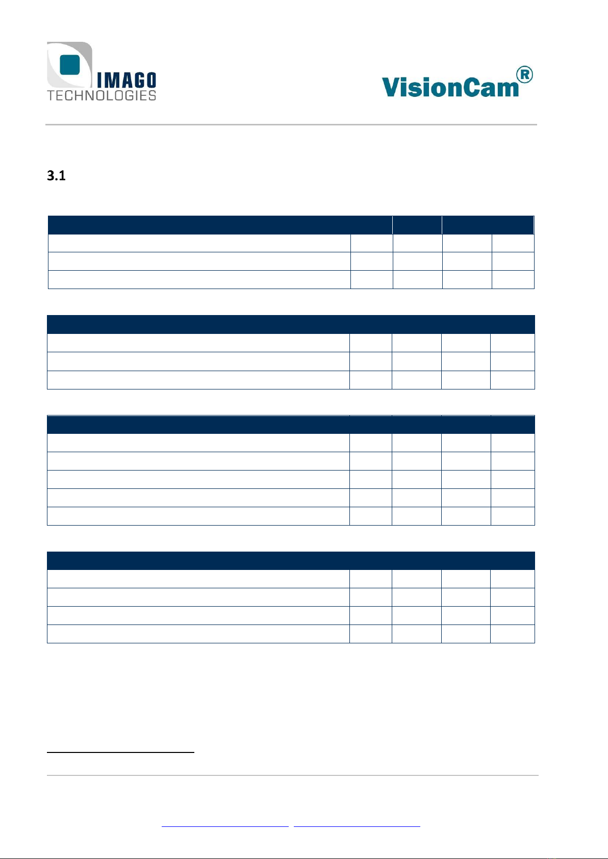
Operating Conditions
Power Supply:
Parameter
Min
Typ.
Max
Unit
Supply voltage
11
26.4
V
Supply voltage for use with internal ring light
24
V
Supply current1(@24V)
0.25
A
RS-232:
Parameter
Min
Typ.
Max
Unit
RX signal input range
–25
25
V
TX output voltage swing (RL= 3 kΩ)
5
5.4
V
Data rate, RL= 3kOhm, CL= 1000 pF
1200
115200
bps
Digital Input:
Parameter
Min.
Typ.
Max.
Unit
Input voltage range
0
30
V
Input current range (limited by internal circuit)
0
21
mA
Threshold voltage
6
11
V
Threshold current
1
5
mA
Input delay
250
ns
Digital Output:
Parameter
Min.
Typ.
Max.
Unit
Common VCC supply voltage (VCC - VOUT)
30
V
Output current, saturated operation: (VCC - VOUT) < 1 V
10
mA
Turn-On time (24 V common VCC, 10 mA)
5
µs
Turn-Off time (24 V common VCC, 10 mA)
15
µs
1
Actual current draw depends on hardware configuration and CPU/system load

3Technical Data Page 9 / 39
IMAGO Technologies GmbH
Strassheimer Str. 45; 61169 Friedberg; Germany; Tel. +49(0)6031-6842611
info@imago-technologies.com; www.imago-technologies.com
Flash (Strobe) Unit:
Parameter
Min
Typ.
Max
Unit
Strobe current range
0.02
2
A
Strobe current step size
10
mA
Continuous current (VSupply=24 V, VLoad=20 V)
130
mA
Minimum flash duration (2 A)
10
µs
Flash duration step size
1
µs
Turn-on delay (2 A)
8
µs
Turn-on delay (100 mA)
80
µs
Turn-off delay (2 A)
3
µs
Turn-off delay (100 mA)
50
µs
RS-422:
Parameter
Min.
Typ.
Max.
Unit
Receiver differential input threshold
-200
200
mV
Receiver input hysteresis
45
mV
Receiver data rate
10
Mbps
Transmitter differential driver output, RL= 100 Ω
2
V
Transmitter differential driver output, open
3.3
V
Transmitter data rate
2
Mbps
5V supply output current
350
mA
12V supply output current
100
mA
Environment:
Parameter
Value
Dimensions
See section 6: Mechanical Drawings
Weight
180 g …310 g
Operating temperature
0 °C …+50 °C
Operating humidity, relative, non-condensing
5 % … 85 %
Storage temperature
-30 °C … +70 °C
Storage humidity, relative, non-condensing
5 % … 95 %
International protection class
IP65 with M12 Ethernet connector,
IP20 with RJ45 Ethernet connector

3Technical Data Page 10 / 39
IMAGO Technologies GmbH
Strassheimer Str. 45; 61169 Friedberg; Germany; Tel. +49(0)6031-6842611
info@imago-technologies.com; www.imago-technologies.com
SoC
The VisionCam uses the TI Sitara AM572x SoC.
TI Sitara AM572x
CPU
2x ARM Cortex-A15 (32 bit)
CPU frequency
1.5 GHz
Memory
1 GB DDR3
Storage
The VisionCam uses a microSD card as mass storage device. It is accessible under a service hatch.
The card stores the bootloader, FPGA firmware and the Linux file system.
SD, SDHC and SDXC (> 32 GB) cards are supported. The maximum interface speed supported is UHS-I
(104 MB/s).
Real-Time Clock
The VisionCam provides a Real-Time Clock which is buffered by a supercapacitor. The capacitor takes
about one day of active power supply to charge fully up. Then, it can then supply the clock for about one
week.
The time can be adjusted with Linux either manually, by a NTP server on the internet, or by a local NTP
server.

4Interfaces Page 11 / 39
IMAGO Technologies GmbH
Strassheimer Str. 45; 61169 Friedberg; Germany; Tel. +49(0)6031-6842611
info@imago-technologies.com; www.imago-technologies.com
4Interfaces
Power and I/O connector
A 17-pin M12 A-coded male connector is used for power supply and I/O signals.
Pin Number
Function
1
Power supply GND
2
Power supply (+)
3
RS-232 TX
4
RS-232 RX
5
Digital IN0
6
Digital IN1
7
Digital IN Common GND
8
Digital OUT0
9
Digital OUT1
10
Digital OUT2
11
Digital OUT3
12
Digital OUT Common VCC
13
Reserved
14
Reserved
15
External LED current +
16
External LED current -
17
Reserved
We recommend using shielded cables, for example:
Length
Product
IMAGO
order code
1.5 m
Phoenix contact 1430284 “SAC-17P- 1,5-35T/FS SH SCO”
10004440
3 m
Phoenix contact 1430297 “SAC-17P- 3,0-35T/FS SH SCO”
10004441
5 m
Phoenix contact 1430307 “SAC-17P- 5,0-35T/FS SH SCO”
10004442
There are also angled and solder versions available.
4Interfaces Page 12 / 39
IMAGO Technologies GmbH
Strassheimer Str. 45; 61169 Friedberg; Germany; Tel. +49(0)6031-6842611
info@imago-technologies.com; www.imago-technologies.com
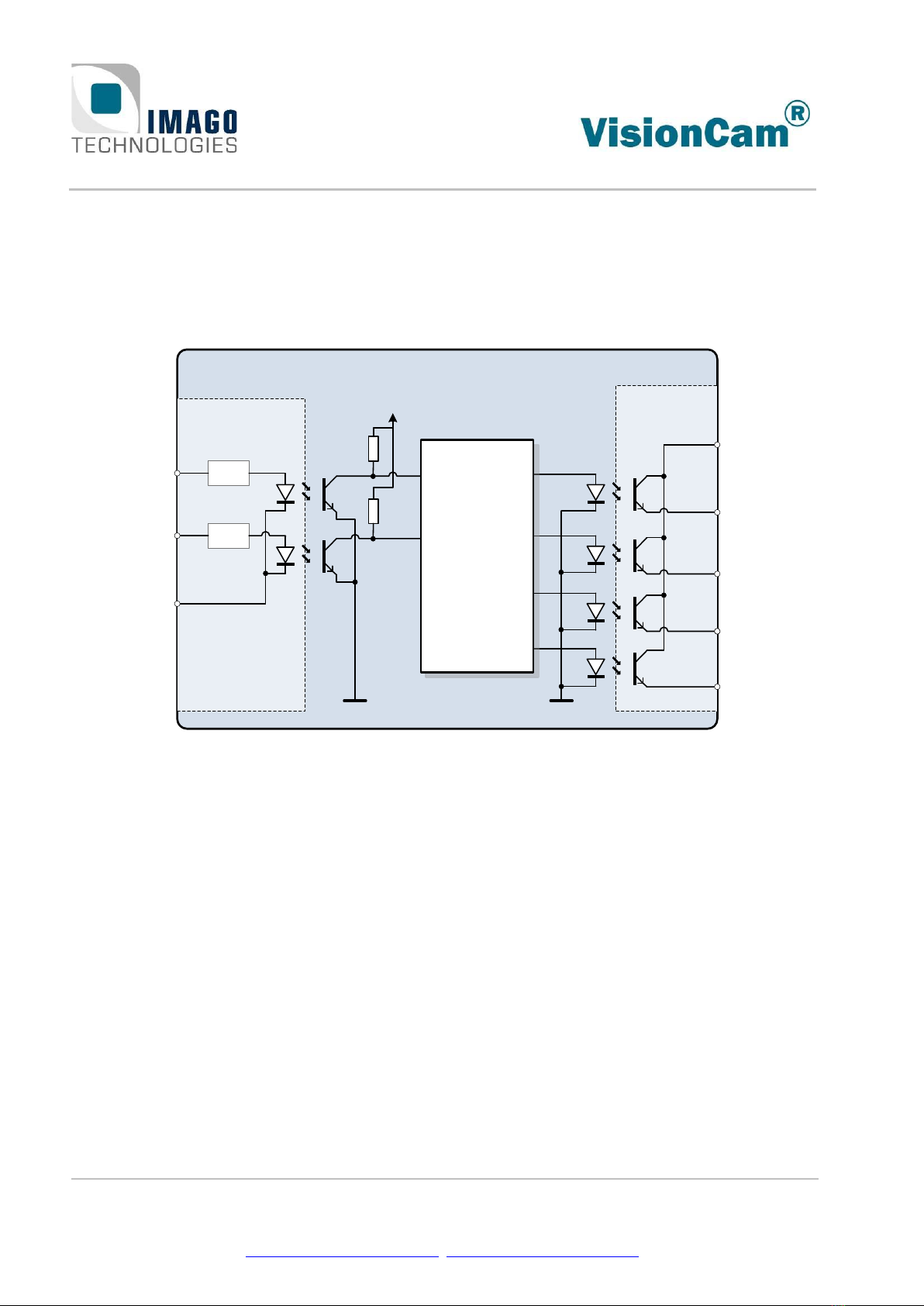
4.1.1 Digital I/O
The digital I/O interface provides two opto-isolated inputs and four opto-isolated outputs. The input group
is electrically isolated from the output group. Both groups are also isolated from other VisionCam circuits
and interfaces.
The following illustration shows the corresponding electrical equivalent circuit:
Galvanic
isolation
OUT 0
VCC
OUT 3
OUT 1
Galvanic isolation
GND
Current
Limit
Current
Limit
IN 0
IN 1 Real-Time
Communication
Controller
(FPGA)
VisionCam
OUT 2
Figure 2: Simplified digital I/O circuit
The input group requires external connection of a shared GND reference.
For the output group, the user must provide a shared supply voltage to the VCC pin. See chapter 4.1 for
the connector pinout.
4Interfaces Page 13 / 39
IMAGO Technologies GmbH
Strassheimer Str. 45; 61169 Friedberg; Germany; Tel. +49(0)6031-6842611
info@imago-technologies.com; www.imago-technologies.com
4.1.2 RS-232
The RS-232 interface is normally used as additional console device for Linux. It can also be configured for
use by a custom application.
The TX and RX signals use the power supply GND pin 1 as reference potential. Make sure that the remote
device uses the same GND reference.
Default settings for the serial interface:
Setting
Value
Baud rate
115200 bps
Parity
None
Data bits
8
Stop bits
1
Flow control
None
Please note that the bootloader U-Boot also uses the serial interface during the boot process. It can be in-
terrupted if a character is received on the RS-232 interface after power-on. The device will then wait for
user input and not boot into the OS.
4Interfaces Page 14 / 39
IMAGO Technologies GmbH
Strassheimer Str. 45; 61169 Friedberg; Germany; Tel. +49(0)6031-6842611
info@imago-technologies.com; www.imago-technologies.com
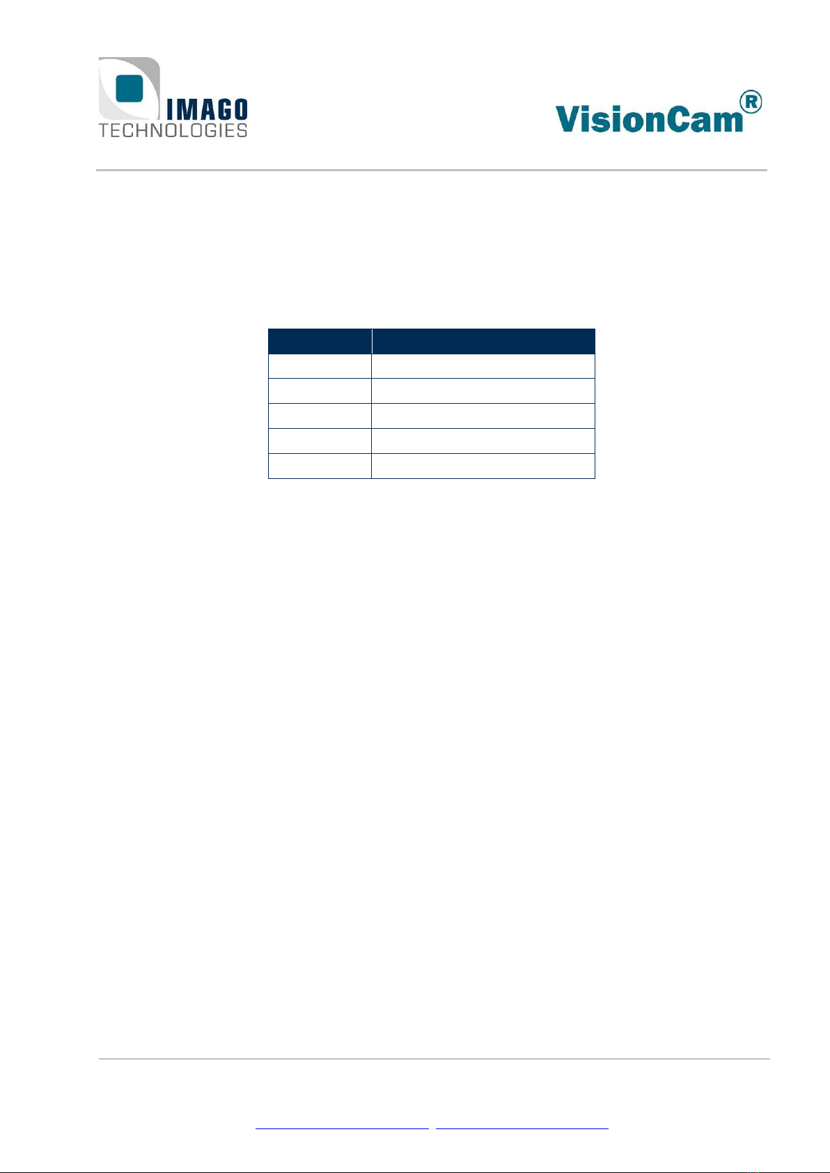
1 Gbit/s Ethernet M12 (IP65)
This option provides an 8-pin M12 X-coded female connector for Ethernet. It is available for the VisionCam
XM and the VisionCam EB.
Pin Number
Function
1
D1+
2
D1-
3
D2+
4
D2-
5
D4+
6
D4-
7
D3-
8
D3+
We recommend using shielded cables, for example:
Length
Product
IMAGO
order code
1 m
Phoenix contact 1407471 “NBC-MSX/ 1,0-94F/R4AC SCO”
10007049
2 m
Phoenix contact 1407472 “NBC-MSX/ 2,0-94F/R4AC SCO”
10007050
5 m
Phoenix contact 1407473 “NBC-MSX/ 5,0-94F/R4AC SCO”
10008076

4Interfaces Page 15 / 39
IMAGO Technologies GmbH
Strassheimer Str. 45; 61169 Friedberg; Germany; Tel. +49(0)6031-6842611
info@imago-technologies.com; www.imago-technologies.com
1 Gbit/s Ethernet RJ45 (IP20)
This option provides an 8P8C modular jack (RJ45) for Ethernet. It is available for the VisionCam XM and the
VisionCam LM.
Pin Number
Function
1
D1+
2
D1-
3
D2+
4
D3+
5
D3-
6
D2-
7
D4+
8
D4-
LED
Function
Left
Ethernet activity (blinking)
Right
Link status (up / down)
We recommend using shielded Cat 5e cables.
4Interfaces Page 16 / 39
IMAGO Technologies GmbH
Strassheimer Str. 45; 61169 Friedberg; Germany; Tel. +49(0)6031-6842611
info@imago-technologies.com; www.imago-technologies.com
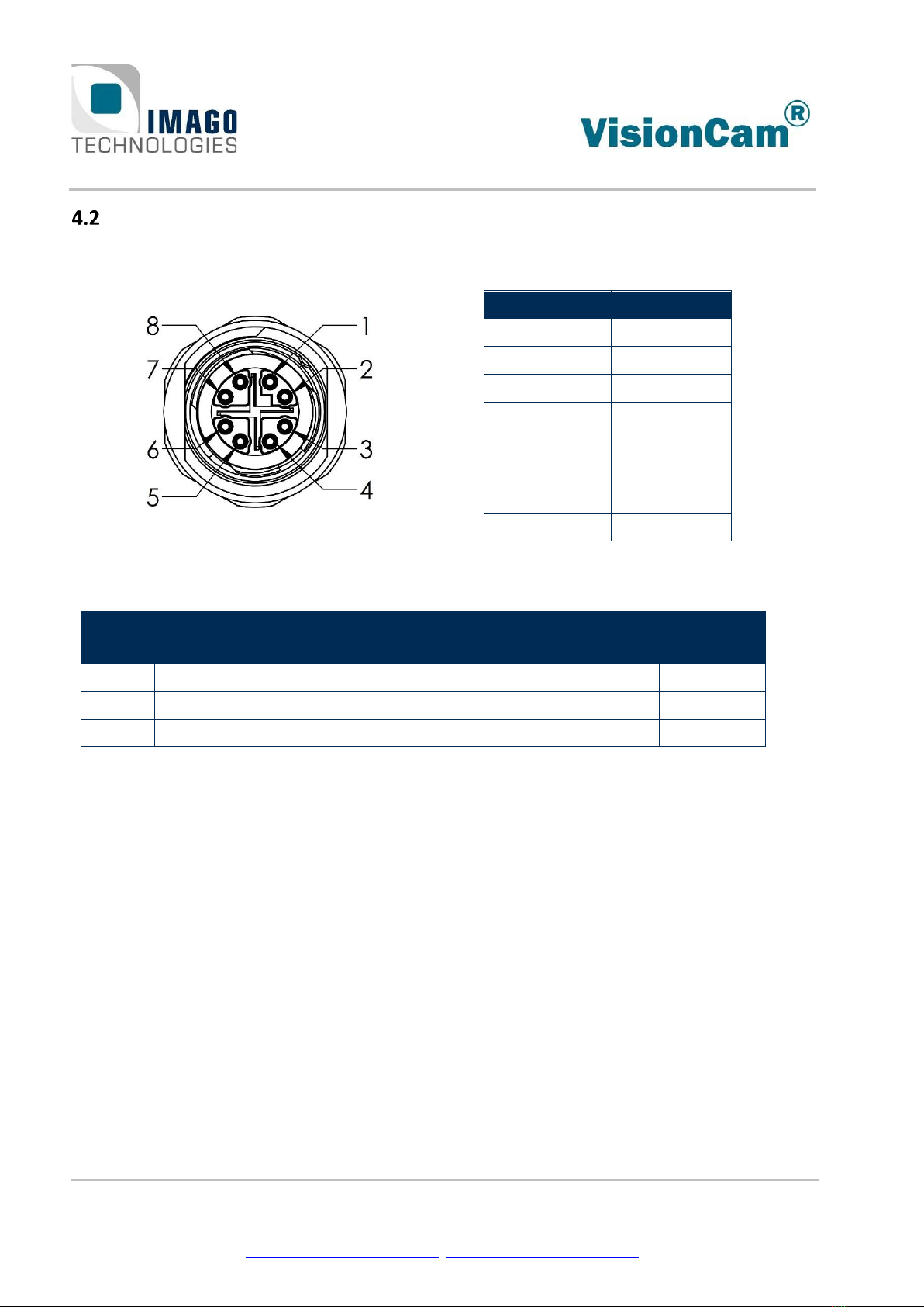
Status LEDs
LED
Green
Red / Yellow
ETH2
Ethernet link is up
Ethernet activity (blinking)
EXP
Sensor exposure active
STR
Internal strobe active
External strobe output active
USR1
Programmable by SDK (LED 2)
USR0
Programmable by SDK (LED 0)
Programmable by SDK (LED 1)
POW
Power on, FPGA configured
Power on, FPGA not configured
I0 … I1
Digital input status
O0 … O3
Digital output status
2
The ETH LED is inactive for the RJ45 connector version.

4Interfaces Page 17 / 39
IMAGO Technologies GmbH
Strassheimer Str. 45; 61169 Friedberg; Germany; Tel. +49(0)6031-6842611
info@imago-technologies.com; www.imago-technologies.com
LED Flash Controller
The LED Flash Controller is designed as a current source. Output current, flash duration and other parame-
ters can be set via software.
The following diagram shows the simplified internal structure for the LED Controller:
CPU
Real-Time
Communication
Controller
(FPGA)
Output Channel
Filter
Current
Regulation
Ext. LED
Lighting
Unit
+24V
Current
reference
Strobe
enable
Current
value
LED +
RSense
LED -
GND
Power
Supply
VisionCam
Int. LED
ring-light
Figure 3: LED Controller structure
The software API allows selection between the internal ring-light (optional) and the external connector.
See chapter 4.1 for connector pinout.
When initializing the strobe controller using the API, the user has to specify a load voltage for the given
current value (see SetLimits() and SetFixedCurrent()). This information is used to protect the
internal circuit against overload by increasing the minimum OFF-time or by limiting the current value. If
there load voltage is not exactly known, lower values should be used because this provides more
protection.
With the internal ring-light, the following load voltages should be used:
Current (mA)
Load voltage (V)
100…499
8
500…999
10
1000…1499
12
1500…1999
15
2000
17

4Interfaces Page 18 / 39
IMAGO Technologies GmbH
Strassheimer Str. 45; 61169 Friedberg; Germany; Tel. +49(0)6031-6842611
info@imago-technologies.com; www.imago-technologies.com
RS-422
The optional RS-422 interface uses a D-SUB15 HD male connector and provides three input and three out-
put signals. The inputs are typically used with a rotary encoder for example.
Pin
Function
Pin
Function
1
In1-
9
Out2+
2
In2-
10
Out1+
3
Out2-
11
In0+
4
Out1-
12
In0-
5
+5 V
13
Out0+
6
GND
14
Out0-
7
In1+
15
+12 V
8
In2+
Connector pins 5 and 15 provide a 5 V / 12 V power supply for RS-422 encoders. See chapter 3 for current
limits.
Do not insert a plug while the device is powered. There is a risk of making a short
circuit on the supply output pins with the connector shield.

5Image Sensors Page 19 / 39
IMAGO Technologies GmbH
Strassheimer Str. 45; 61169 Friedberg; Germany; Tel. +49(0)6031-6842611
info@imago-technologies.com; www.imago-technologies.com
5Image Sensors
This chapter will give you a short overview about the available sensors for the VisionCam. On the next
pages you will find more detailed information for each sensor.
Area Scan Sensors:
Aptina WVGA
MT9V032M
MT9V032C
e2v SXGA
EV76C560M
EV76C560C
e2v UXGA
EV76C570M
EV76C570C
ON Semi.
NOIP3SN5000A
Optical format
1/3”
1/1.8”
1/1.8”
1.1”
Resolution
752 × 480
1280 × 1024
1600 × 1200
2592 x 2048
Framerate
(full resolution)
63 fps
45 fps
39 fps
40 fps
Framerate
(VGA)
74 fps
95 fps
92 fps
460 fps
Type
Monochrome or
Bayer pattern
Monochrome or
Bayer pattern
Monochrome
or Bayer pat-
tern
Monochrome or
Bayer pattern
Event-Based Sensor:
Prophesee PPS3MVCD
Optical format
3/4’’ (12mm diagonal)
Resolution
640 × 480 (VGA)
Event rate (full resolution)
50 million events per second
Pixel size
15 µm × 15 µm
5Image Sensors Page 20 / 39
IMAGO Technologies GmbH
Strassheimer Str. 45; 61169 Friedberg; Germany; Tel. +49(0)6031-6842611
info@imago-technologies.com; www.imago-technologies.com
Line Scan Sensors:
ams Dragster
DR-2k-7
ams Dragster
DR-4k-7
ams Dragster
DR-4k-3.5
ams Dragster
DR-8k-3.5
Number of pixels
1 × 2048
1 × 4096
1 × 4096
1 × 8192
Pixel size
7 µm × 7 µm
7 µm × 7 µm
3.5 µm × 3.5 µm
3.5 µm × 3.5 µm
Sensitive length
14.34 mm
28.67 mm
14.34 mm
28.67 mm
Max. line rate
80 kHz
80 kHz
80 kHz
46 kHz
Type
Monochrome
Monochrome
Monochrome
Monochrome
Dual-Line Scan Sensors:
ams Dragster
DR-2x2k-7
ams Dragster
DR-2x4k-7
ams Dragster
DR-2x2k-7-RGB
ams Dragster
DR-2x4k-7-RGB
Number of pixels
2 × 2048
2 × 4096
2 × 2048
2 × 4096
Pixel size
7 µm × 7 µm
7 µm × 7 µm
7 µm × 7 µm
7 µm × 7 µm
Sensitive length
14.34 mm
28.67 mm
14.34 mm
28.67 mm
Max. scan rate
80 kHz
46 kHz
80 kHz
46 kHz
Type
Monochrome
Monochrome
Bayer filter
Bayer filter
Other manuals for VisionCam XM
1
This manual suits for next models
2
Table of contents
Other IMAGO Digital Camera manuals

Popular Digital Camera manuals by other brands


Kodak
Kodak Pixpro X52 quick start guide

Argus
Argus QC-5340 Specifications

CIS
CIS VCC-SXCXP5M Product specification & operational manual

Olympus
Olympus IR 300 - Digital Camera - 5.0 Megapixel Basic Manual

Interlogix
Interlogix UltraView UVC-6130-1 user manual
Olympus
Olympus IR 300 - Digital Camera - 5.0 Megapixel Manuel Avancé