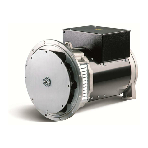
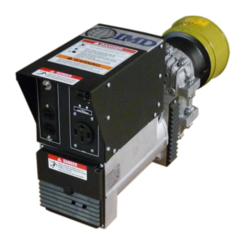
IMD PTO15/2S User manual

International Manufacturing & Design LLC
Owner’s Manual
PTO10/2S - PTO15/2S
(Photo is not representative for all model types)

Page 2
Introduction
Congratulations on your selection of this PTO Gen-Set. We are certain you will be pleased
with your purchase of one of the finest PTO-generators on the market today.
We want to help you get the best results from your new PTO-generator and to operate it
safely. This manual contains the information on how to do that; please read it carefully.
As you read this manual, you will find information preceded by a WARNING symbol. That
information is intended to help you avoid damage to your unit, other property, the environment
or your safety.
We suggest you read the warranty policy to fully understand its coverage and your
responsibilities of ownership.
When your PTO-generator needs scheduled maintenance, keep in mind that your servicing
dealer is specially trained in servicing the unit. Your servicing dealer is dedicated to your
satisfaction and will be pleased to answer your questions and concerns.
Should you not be satisfied with your dealer, please write to
IMD LLC
Customer Service
2607 Woodruff Rd. Suite E-310
Simpsonville; SC 29681

Page 3
CONTENTS
1) Safety Instructions
2) Controls Panel
3) Before Operation
Is your PTO-generator ready to go?
Check the general condition of the PTO-generator.
Check the general condition of the equipment powered by the PTO-generator.
4) Operation
Starting the PTO-generator
How to power tools or electrical items
Shutting off the PTO-generator
PTO alignment
5) Servicing your PTO-generator
The importance of maintenance
Warranty
6) Helpful Suggestions
Storage
Transportation
7) Technical Information
IMD LLC
Customer Service
2607 Woodruff Rd. Suite E-310
Simpsonville; SC 29681
USA
Tel.: 864 295 6773

Page 4
1. Safety Instructions
WARNING-------------------------------------------------------------------------------------------------------------
PLEASE READ AND UNDERSTAND THIS MANUAL COMPLETELY BEFORE OPERATING
THE MACHINE
----------------------------------------------------------------------------------------------------------------------------
THE SAFETY ALERT SYMBOL MEANS--------------------------------------------------------------------
YOU CAN BE KILLED OR SERIOUSLY HURT IF YOU DON’T FOLLOW INSTRUCTIONS
---------------------------------------------------------------------------------------------------------------------------
You will find safety information in a variety of forms, including:
Safety Messages preceded by a safety alert symbol and one signal word, WARNING or
DANGER.
Contents
a) Important Safety Information
b) Electric Shock Prevention
c) Connection
d) Fire Hazard
e) Deadly Exhaust Gas
f) Noise Hazard
g) Operation
h) Explanation of The Different Safety Labels

Page 5
Safety Instructions
a) Important Safety Instructions
Most accidents involved with PTO-generators can be prevented if you follow all the
instructions in the owners manual. Some of the most common hazards are discussed below.
Reading this manual carefully provides the best way to protect yourself and others.
b) Electric Shock Prevention
Never operate the PTO-generator in rain or snow. Never touch the machine with wet hands or
electrical shock could occur.
c) Connection
Before the PTO-generator can be connected to a building’s electrical system, a licensed
electrician must install an isolation (transfer) switch in the building’s main fuse box. The switch
is the connection point for PTO-generator power and allows selection of PTO-generator or
main line power to the building. This will prevent the PTO-generator from charging the main
power line (backfeeding) when the main power supply has failed or has been turned off for
line repair. Backfeeding can electrocute or injure line maintenance personnel. Also, PTO-
generator and building electrical system damage can occur when normal operating power
returns if unit is used without an isolation switch.

Page 6
Do not connect the PTO-generator to commercial power outlet in parallel with any other
generator.
d) Fire Hazard
Gasoline, diesel and other fuels always present a hazard of possible explosion and/or fire.
Keep a fire extinguisher nearby and know its proper use. Fire extinguisher rated ABC by
NFPA is appropriate.
e) Deadly exhaust gas
Exhaust fumes from any engine contain carbon monoxide, an invisible odorless and deadly
gas that must be mixed with fresh air. Operate your PTO-generator only in well-ventilated
areas. Never operate indoors.

Page 7
f) Noise hazard
Excessive noise is not only tiring, but continual exposure can lead to loss of hearing.
Use hearing protection equipment when working around this equipment for a long period of
time.
Keep your neighbors in mind when permanently installing this equipment.
g) Operation
PTO drive shafts (tumbling bars) have many inherent dangers, extreme caution must be
exercised when using them.
-Never allow children around a drive shaft when it is in operation.
-Keep all safety guards and shields in place and securely tightened, do not operate without
shaft safety cover.
-Never operate a drive shaft that has been damaged or had safety shield removed.
-Never step over a drive shaft while it is running.
-Never wear a necktie, loose articles of clothing or anything else that can be caught in
moving parts.
-Never try to stop a turning drive shaft with your hand or your foot.
-Utilize the cardan shaft with the protection.
-When starting or stopping, all loads must be disconnected to prevent sudden kickbacks,
which could damage the PTO-generator or the anchorages.

Page 8
h) Explanation of the different safety labels:
Extremely high and dangerous voltage is present at the power terminals.
Contact with power terminals will result in extremely dangerous – possibly lethal – electric
shock.
Do not open the flap and touch the modular connector receptacle when the PTO-generator
(PTO-15-2S only) is in operation or switched on. Use extreme caution!
Never handle any kind of electrical device while standing on water, while barefooted or while
hands or feet are wet. Dangerous electric shock that can cause severe personal injuries or
death will result.

Page 9
The PTO-shaft, which connects the tractor and the PTO-generator, transmits torque to the
PTO-generator during normal operation. The PTO-generator can tip over, causing personal
serious injury and damage. Therefore the PTO-generator must be secured on a concrete
foundation. Please see installation instructions.
Before operation, make sure that the oil level in the gearbox is sufficient (max. oil level 0.5
liter).
The power take-off (PTO) shaft represents extreme danger. Fatal injuries may result if
protective devices are not used properly and at all times:
-Never stand near the PTO-shaft if it is in operation.
-Always make sure that all safety devices are correctly in place.
-Replace any damaged safety devices immediately and do not operate the equipment until
such replacement is made.
-The PTO shaft safety guard must be able to rotate freely.
-Always wear close-fitting clothing and tie back long hair.
-Avoid any contact of your hair and/or clothing with the rotating shaft.
-For any maintenance on the PTO-shaft, please see shaft manual.

Page 10
2. Controls:
Panel:
Always verify that the PTO
-
generator is
properly grounded before use !
Voltmeter
50 Amp receptacle
20 Amp duplex receptacle
Main circuit
breaker

Page 11
3. Before Operation
Is your PTO-generator ready to go?
Check the general condition of the PTO-generator:
Ground: Make sure to ground (earth) the PTO-generator with sufficient current capacity.
Ground (earth) lead diameter:
0.12 mm (0.005 in) / Ampere
Example: 10 Ampere => 1.2 mm ( 0.05 in)
Gear box: Check the fluid level and top up if necessary (up to 0.5l in total).
Check the general condition of the equipment powered by the PTO-generator:
Make sure that there’s no tool or electrical item plugged in before starting the PTO-generator.
Make sure the tool is turned off before plugging it in.
PTO alignment:
Position the PTO-generator in such a manner that the power take-off shaft is as near to direct
line in all directions as possible. This will increase the life of the power take-off shaft, reduce
ware on bearings of both the power take-off and the alternator, and reduce vibration. The
maximum angle from a straight line should not exceed 10°. For the nominal power take-off
shaft length of 42", 10°is equal to 8" misalignment. For extended distance the maximum
misalignment would increase 2" for each foot.
For Example: For a 6'PTO shaft the maximum misalignment is 12" from a straight line.

Page 12
4. Operation
Starting the PTO-generator:
1. Set the main circuit breaker on the PTO-generator panel to “off”.
2. Connect the power take-off shaft securely to the PTO-generator and the tractor. Position
as near to a straight line as possible.
3. Adjust power take-off speed to maximum speed then back down to maintain the voltage
indicator around 240/120 Volt.
4. Place plug in receptacle
5. Place load circuit breaker in the “on” position. If the breaker trips, check the short circuit or
grounded connection in the load cable to the double throw switch. A breaker that trips must
be reset by moving to “off” before re-closing. See PTO-shaft instructions for more detail.
6. Keep the meter in the green by adjusting the tractor speed.
How to power tools or other electrical items:
Please make sure that the apparatus you will power by the PTO-generator does not exceed
the PTO-generator’s ampere and voltage capacity. Before plugging in the electrical apparatus,
make sure that the circuit breakers and protectors are in the “off” position and that the
electrical unit or tool will not start during connection with your PTO-generator or during
controlling the circuit breakers and protectors. Plug your apparatus in the fitting NEMA Socket
of the PTO-generator. After plugging in, bring the circuit breakers and protectors in the “on”
position and start your tool or apparatus. If you want to power different electrical units at the
same time, make sure that the PTO-generator’s voltage and ampere capacity is sufficient.
Shutting off the PTO-generator:
1. Place the main circuit breaker in “off” position.
2. Disconnect all load to the PTO-generator.
3. Slowly reduce power Take-off speed to a minimum and disengage the power take-off.
Some tractors have a brake on the power take-off, which stops the shaft instantly.
Stopping the alternator rotor instantly from rated speed may result in a broken
shaft.

Page 13
5. Servicing your PTO-generator
All maintenance operations must be carried out with the machine shut off.
Ordinary maintenance consists of some simple operations to be carried out periodically.
Oil check: Check the PTO-generator gear case oil level before each use of the PTO-
generator. Maintain the oil level before each use of the PTO-generator. Maintain the oil level
at 0.5 liter. The PTO-generator is shipped without lubricant in the gear case.
Specifications for gear case lubricant are:
API Service GL-5 EP Rated, Grade SAE 85W-90-140.
The following kinds of oil are recommended for use in the PTO-generator gear case:
Mobil SAE 85W90-140 API Service GL-5, Sunoco/DX XLSOW90-140, Kendal Three Star
BSW-140, Amoco 85W140 or equivalent.
The PTO-generator bearings are factory lubricated and sealed, and require no further
lubrication. The splinted PTO-generator input shaft should be cleaned and lubricated with a
thin film of grease before and after each use of the PTO-generator. The drive shaft (tumbling
bar) requires greasing.
See the following picture for lubrication schedule.
Cleaning ventilation grids: it is important to keep the alternator ventilation grids clean to
prevent overheating of the alternator. If the grids are covered with leaves, weeds and pieces
of paper, it could cause overheating of the alternator windings and serious damage to the
equipment.
Screw tightening: the screws that connect the PTO-generator to the frame must periodically
be tightened to ensure perfect functioning and safe use. Worn screws must be replaced
immediately.

Page 14
Warranty:
NOTICE: THIS LIMITED WARRANTY GIVES YOU CERTAIN RIGHTS. PLEASE READ
CAREFULLY.
The manufacturer provides a limited warranty and warrants the product to be free from defects
in material and workmanship from the date of original purchase from an authorized dealer for
a period of 6 months. This warranty is not transferable and only covers the initial original
purchaser. Proof of purchase (original sales receipt) is required for any warranty claim.
In the event of a defect in material or workmanship during this 6 month period from the date of
the original purchase, the manufacturer or its authorized dealer or repair center will, at the
manufacturer’s sole discretion, repair or replace the product on the terms and conditions and
with the limitations and exclusions as set forth below:
1. The manufacturer may repair the product with new or reconditioned parts or replace the
product with a new or reconditioned product of the same or substantially similar or equivalent
kind, and any replaced products or parts become the property of the manufacturer.
2. This limited warranty does not cover damage caused by abuse, neglect, accident, disaster,
misuse, mishandling, mispackaging for shipping, improper installation, improper operation,
overload, mechanical impact, chemical impact or damage caused by any chemicals other than
the ones authorized to be used in connection with the operation of the product, unauthorized
repair or modification, use of non-proprietary or aftermarket spare parts, or failure to follow the
manufacturer’s instructions with respect to the proper handling, operations, installation,
service and maintenance of the product.
3. Normal wear and tear are not covered by this limited warranty.
4. To obtain warranty service, contact your dealer or the manufacturer to receive shipping
instructions and return authorization.
5. To obtain warranty service, defective parts must be shipped to the manufacturer. The
purchaser must pay the shipping charges to ship the parts to the manufacturer. If the entire
generator is returned for warranty service the gearbox must be drained of all fluids, packaged
in its original container, and shipping charges must be paid by the purchaser. Return charges
will be paid by the manufacturer.
6. This limited warranty does not cover any on-site repair.
7. Any repairs done under this limited warranty do not extend the warranty period beyond the
date of 6 months from the original purchase date.
8. This limited warranty shall be null and void in case of abuse, neglect, accident, disaster,
misuse, mishandling, mispackaging for shipping, improper installation, improper operation,
overload, mechanical impact, chemical impact or damage caused by any chemicals other than
the ones authorized to be used in connection with the operation of the product,

Page 15
unauthorized repair or modification, use of non-proprietary or after-market spare parts, or
failure to follow the manufacturer’s instructions with respect to the proper handling, operation,
installation, service and maintenance of the product.
9. This limited warranty is limited to replacement of the defective parts of the product or the
whole product, if found defective.

ANY IMPLIED WARRANTY OF MERCHANTABILITY OR FITNESS FOR A PARTICULAR
PURPOSE ON THIS PRODUCT IS LIMITED TO THE 6-MONTHS DURATION OF THIS
WRITTEN WARRANTY. ALL WARRANTIES SET FORTH IN THIS WARRANTY ARE
LIMITED TO 6 MONTHS FROM THE DATE OF THE ORIGINAL PURCHASE. NO
WARRANTIES WHATSOEVER WILL COVER THE PRODUCT BEYOND THE 6-MONTHS
PERIOD. HOWEVER, SOME STATES DO NOT ALLOW LIMITATIONS ON HOW LONG AN
IMPLIED WARRANTY LASTS, SO IN SUCH STATES THE ABOVE LIMITATION MAY NOT
APPLY TO YOU.
IF THIS PRODUCT IS DEFECTIVE, YOUR ONLY REMEDY IS REPAIR OR
REPLACEMENT, AS DESCRIBED ABOVE. UNDER NO CIRCUMSTANCES WILL THE
MANUFACTURER, ITS DISTRIBUTORS, DEALERS OR AGENTS BE LIABLE FOR
INCIDENTAL OR CONSEQUENTIAL DAMAGES, INCLUDING ANY LOST PROFITS, LOST
COMPENSATION OF ANY KIND, OR OTHER DAMAGES CAUSED BY THE USE OF THIS
PRODUCT OR INABILITY TO USE IT, EVEN IF THE DEALER OR MANUFACTURER HAS
BEEN ADVISED OF SUCH LIABILITY CLAIMS OR OTHER CLAIMS.
SOME STATES DO NOT ALLOW THE EXCLUSION OR LIMITATION OF INCIDENTAL OR
CONSEQUENTIAL DAMAGES, SO THE ABOVE LIMITATION OR EXCLUSION MAY NOT
APPLY TO YOU. THIS WARRANTY GIVES YOU SPECIFIC RIGHTS, AND YOU MAY HAVE
OTHER RIGHTS WHICH MAY VARY FROM STATE TO STATE.

Page 16
6. Helpful Suggestions
Transportation:
(If equipped with a 3-point hitch)
The PTO-series generators are designed to be handled anchored to the three points of the
tractor hoist. If necessary for lifting the PTO-generator, the points indicated in the following
picture may be used as coupling points.
The PTO-generator is connected to the tractor hoist fastening by three hitch points (drawing
ref 1-2-3).
Check that the anchorages are well secured before starting the tractor. To transmit power
from the motor to the PTO-generator use a double-joint cardan shaft of adequate length and
fitted with a safety circuit breaker.
Before starting rotation of the propeller shaft, place the PTO-generator on the ground.
Storage:
Proper Storage preparation is essential for keeping your PTO-generator trouble-free and
looking good. The following information will keep rust and other corrosion from impairing your
machine’s function and appearance, and will make the unit easier to start when you use it
again.
If the PTO-generator is not to be used for a long time, it is recommended, before storage, to
clean all the parts thoroughly, protect the metallic parts with a film of oil and to wrap the PTO-
generator in a nylon sheet to protect it against humidity.
It is recommended to exercise this PTO generator for one hour, carrying rated load at
least twice a year.

Page 17
7. Technical Specifications
PTO-Specifications
PTO 10/2 S PTO 15/2 S
Generator Synchronous Synchronous
2-Pole 2-Pole
Alternator Speed 3600 rpm 3600 rpm
AC Output Max. 120V / 240V 120V / 240V
10.000 W 15.000 W
(83A / 42A) (125A / 62.5A)
Take Off Shaft Power 20 HP 29 HP
Shaft Speed Standard 540 rpm Standard 540 rpm
Receptacles b,h b,h,I
Dimensions (LxWxH) 29x35x38 35x35x38
Dry Weight 209 lbs 284 lbs
Receptacles: I)125V/250V 175A
b) Duplex 125V 5-20 h) 50A 125V/250V L14-50
Options
Simultaneous 120V/240V Use X X
Full Power 240V Outlet X X
Voltmeter X X
Magnetic Circuit Breaker X X
PTO 3-Point Hitch for Traktor O
PTO Base for Trailer or
Stand-By Mount O O
O=optional : X=standard

Page 18
Wiring Diagrams:
Wiring Diagram PTO10/2S:

Page 19
Wiring Diagram PTO15/2S:
This manual suits for next models
1
Table of contents
Other IMD Portable Generator manuals
Popular Portable Generator manuals by other brands

AL-KO
AL-KO 2500-C Instructions for use

HP
HP 70300A Installation and Verification Guide

Champion Power Equipment
Champion Power Equipment 41153 Owner's Manual and Operating Instructions

Powermate
Powermate PM0435000 manual

DuroStar
DuroStar DUROMAX DUAL FUEL XP8500EH user manual

National Instruments
National Instruments FD-11601 user guide