IMD PTO10/2S User manual

IMD LLC_____________________________________________________ 1
10011-12 04/15
Foreword
Congratulations on the purchase of your new power take-off (PTO) generator. We hope
that you will find your IMD PTO generator a pleasure to use.
The operating instructions will help you to become acquainted with your new equipment.
Important safety instructions ad hazard warnings will help you to use your PTO generator
safely.
The PTO generator provides a quick source of electrical power for the agricultural
environment.
Please observe the following points before putting your PTO generator into operation:
Read its Owner’s Manual carefully and in its entirety.
Observe and follow all safety instructions, including the warning labels on the PTO
generator at all times.
Immediately replace any defective warning labels so that no unsuspecting persons are
injured.
Read the operating instructions from the tractor and power take-off shaft manufacturers
and follow all instructions carefully.
If there is anything that you do not understand, please contact our
service Hotline at 864. 968.0858 for clarification and technical
assistance.
We reserve the right to make technical modifications and changes at any time with or
without notice.

IMD LLC_____________________________________________________ 2
10011-12 04/15
Table of Contents
Foreword 1
Table of Content 2
Intended Usage 3
Conditions of Warranty 3
Safety Instructions 6
General Safety Instructions 7
Mechanical Danger 7
Danger from exhaust fumes 8
Danger from Electrical power 8
Danger from explosion 9
Preparing for use: 10
Delivery Conditions 10
Mounting onto concrete slab 10
Optional 3-point hitch 11
Optional heavy duty trailer 12
Electrical Installation 12
Grounding the generator 13
Installing PTO shaft 14
Checking the gearbox for oil level 14
Operation 15
Switch ON 15
Starting the generator 15
Switching OFF 16
Maintenance, cleaning, care 16
Visual Inspection 17
Functional Test 17
Keeping the generator clean 17
Changing the gear oil 18
Long term storage 19
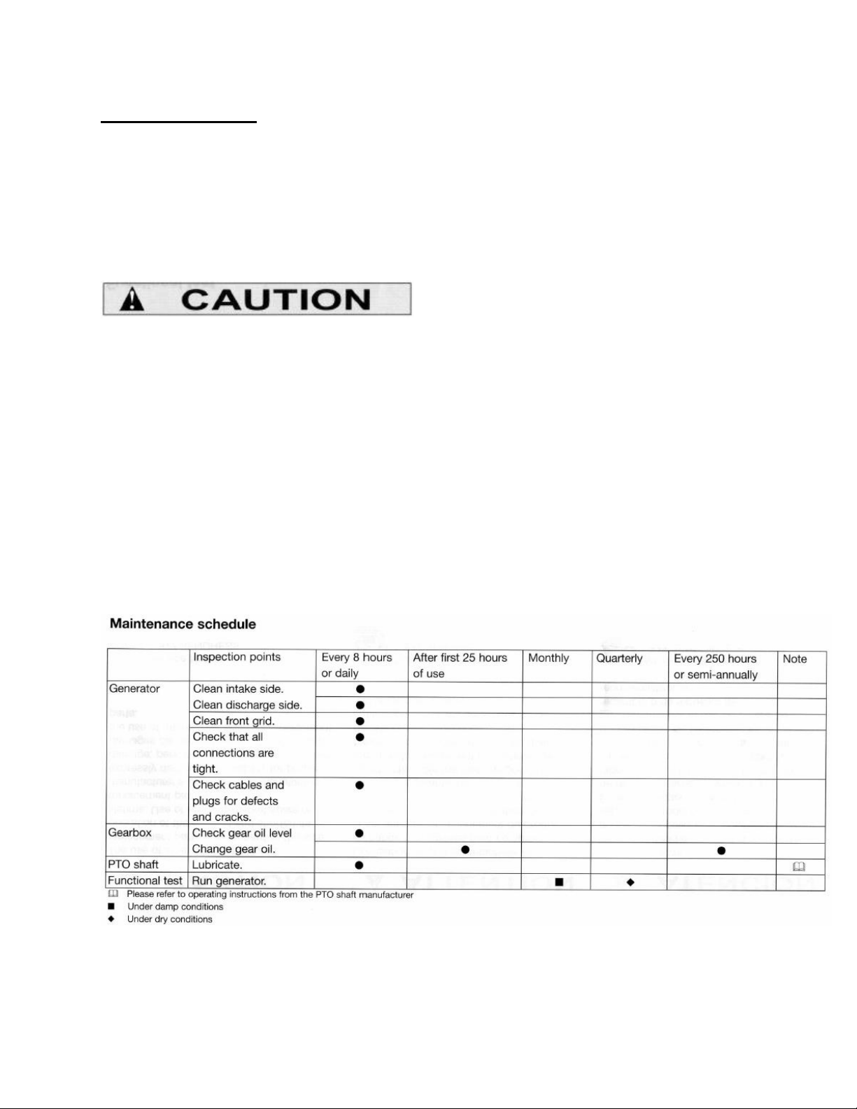
Maintenance schedule 19
Technical Specification 20
Exploded view alternator 20
Circuit Diagram 21
Parts List Panel 21
Exploded view panel 22
Accessories 23
Terminology 23
Troubleshooting 24
Spare Parts 24

IMD LLC_____________________________________________________ 3
10011-12 04/15
Intended Usage
The intended usage of this PTO generator is the generation of electrical power.
The IMD power generator can be used to feed electrical power into the circuit of a
building (provided the proper electrical safety switch has been installed by a licensed
electrician) or to plug appropriate electrical applications into its power outlets to operate
them in case of a power outage.
Any different or additional use of the equipment is not within the scope of the intended
usage and shall be at the owner’s or operator’s own risk and peril.
The manufacturer disclaims any and all liability for any such unauthorized, additional or
different use, and shall be held harmless for any and all losses and damages, including
property damage, personal injury and death, resulting from any such unauthorized,
additional or different use, to the operator, any bystanders or any other person or property.
Any modifications to any IMD PTO generator shall be made only in accordance with the
manufacturer’s specifications, upon written approval by the manufacturer and shall be
performed only by a trained licensed professional.
Unauthorized modifications of the equipment or any unauthorized use of the equipment or
use outside the scope of the intended usage shall void the manufacturer’s warranty.
Conditions of Warranty
NOTICE: THIS LIMITED WARRANTY GIVES YOU CERTAIN RIGHTS. PLEASE
READ CAREFULLY.
The manufacturer provides a limited warranty and warrants the product to be free from
defects in material and workmanship from the date of original purchase from an authorized
dealer for the duration of the warranty. This warranty is not transferable and only covers
the initial original purchaser. Proof of purchase (original sales receipt) is required for any
warranty claim.
No warranty coverage will be provided without proof of purchase or warranty card.

IMD LLC_____________________________________________________ 4
10011-12 04/15
In the event of a defect in material or workmanship during the 24 month period from the
date of the original purchase, the manufacturer or its authorized dealer or repair center
will, at the manufacturer’s sole discretion, repair or replace the product on the terms and
conditions and with the limitations and exclusions as set forth below:
1. The manufacturer may repair the product with new or reconditioned parts or replace the
product with a new or reconditioned product of the same or substantially similar or
equivalent kind, and any replaced products or parts become the property of the
manufacturer.
2. This limited warranty does not cover damage caused by abuse, neglect, accident,
disaster, misuse, mishandling, improper packaging for shipping, improper installation,
improper operation, overload, mechanical impact, chemical impact or damage caused
by any chemicals other than the ones authorized to be used in connection with the
operation of the product, unauthorized repair or modification, use of non-proprietary or
aftermarket spare parts, or failure to follow the manufacturer’s instructions with respect
to the proper handling, operation, installation, service and maintenance of the product.
3. Normal wear and tear is not covered by this limited warranty.
4. To obtain warranty service, contact your dealer or the manufacturer to receive shipping
instructions and return authorization.
Service Hotline
1.864.968.0858
5. To obtain warranty service, defective parts must be shipped to the manufacturer. The
purchaser must pay the shipping charges to ship the parts to the manufacturer. If the
entire generator is returned for warranty service the gearbox must be drained of all
fluids, packaged in its original container, and shipping charges must be paid by the
purchaser. Return charges will be paid by the manufacturer.
6. This limited warranty does not cover any on-site repair.
7. Any repairs done under this limited warranty do not extend the warranty period beyond
the date of 24 months from the original purchase date.

IMD LLC_____________________________________________________ 5
10011-12 04/15
8. This limited warranty shall be null and void in case of abuse, neglect, accident, disaster,
misuse, mishandling, improper packaging for shipping, improper operation, overload,
mechanical impact, chemical impact or damage caused by any chemicals other than the
ones authorized to be used in connection with the operation of the product,
unauthorized repair or modification, use of non-proprietary or after-market spare parts,
or failure to follow the manufacturer’s instructions with respect to the proper handling,
operation, installation, service and maintenance of the product.
9. This limited warranty is limited to replacement of the defective parts of the product or
the whole product, if found defective.
10. This limited warranty covers the labor required to repair the unit for the first 12 months
only.
ANY IMPLIED WARRANTY OF MERCHANTABILITY OR FITNESS FOR A
PARTICULAR PURPOSE ON THIS PRODUCT IS LIMITED TO THE 24-MONTHS
DURATION OF THIS WRITTEN WARRANTY. ALL WARRANTIES SET FORTH IN
THIS WARRANTY ARE LIMITED TO THE 24 MONTHS FROM THE DATE OF THE
ORIGINAL PURCHASE. NO WARRANTIES WHATSOEVER WILL COVER THE
PRODUCT BEYOND THE 24-MONTHS PERIOD. HOWEVER, SOME STATES DO
NOT ALLOW LIMITATIONS ON HOW LONG AN IMPLIED WARRANTY LASTS,
SO IN SUCH STATES THE ABOVE LIMITATION MAY NOT APPLY TO YOU.
IF THIS PRODUCT IS DEFECTIVE, YOUR ONLY REMEMDY IS REPAIR OR
REPLACEMENT, AS DESCRIBED ABOVE. UNDER NO CIRCUMSTANCES WILL
THE MANUFACTURER, ITS DISTRIBUTORS, DEALERS OR AGENTS BE LIABLE
FOR INCIDENTAL OR CONSEQENTIAL DAMAGES, INCLUDING ANY LOST
PROFITS, LOST COMPENSATION OF ANY KIND, OR OTHER DAMAGES
CAUSED BY THE USE OF THIS PRODUCT OR INABILITY TO USE IT, EVEN IF
THE DEALER OR MANUFACTURER HAS BEEN ADVISED OF SUCH LIABILITY
CLAIMS OR OTHER CLAIMS.
SOME STATES DO NOT ALLOW THE EXCLUSION OR LIMITATION OF
INCIDENTAL OR CONSEQUENTIAL DAMAGES, SO THE ABOVE LIMITATION
OR EXCLUSION MAY NOT APPLY TO YOU. THIS WARRANTY GIVES YOU
SPECIFIC RIGHTS, AND YOU MAY HAVE OTHER RIGHTS WICH MAY VARY
FROM STATE TO STATE.

IMD LLC_____________________________________________________ 6
10011-12 04/15
Safety Instructions
Read these operating instructions carefully, as well as those of the tractor and PTO shaft
manufacturer. For safety reasons, you should not use the generator set until you have
understood all the instructions.
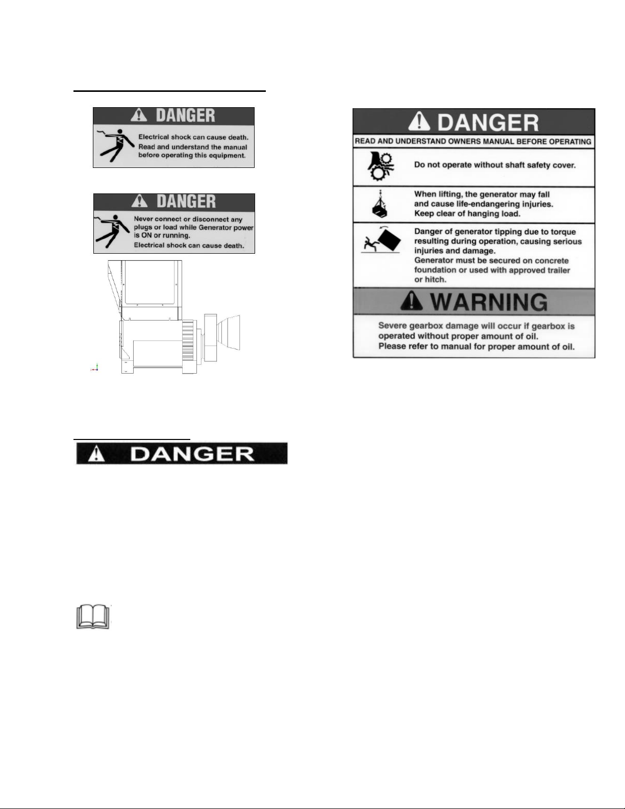
This is the safety alert symbol. It is used to alert you to potential personal injury
hazards. Obey all safety messages that follow this symbol to avoid possible injury or
death.
Wherever the Danger sign appears in this manual it indicates an imminently hazardous
situation which, if not avoided, will result in death or serious personal injury.
The Warning sign indicates a potentially hazardous situation which, if not avoided, could
result in death or serious personal injury.
Ground (earth) terminal - Be sure to ground (earth) the generator.
This symbol tells you to read the operating instructions of the tractor manufacturer
and the PTO shaft manufacturer.
IMD LLC_____________________________________________________ 7
10011-12 04/15
General Safety Instructions
Mechanical danger
Operate the generator and tractor only when all protective devices have been installed
properly and correctly.
Before starting up the tractor, make sure that no one is standing in close proximity to
the tractor or generator, particularly children.
Watch out for children in particular because they tend to be attracted to machinery in
operation.
Read and understand the operating instructions from the tractor manufacturer.
The power take-off shaft (PTO) represents extreme danger. Fatal injuries may result if
protective devices are not used properly and at all times.
Never stand near the PTO shaft while it is in operation.
Always make sure that all safety devices are correctly in place.

IMD LLC_____________________________________________________ 8
10011-12 04/15
Replace any damaged safety devices immediately and do not operate the equipment
until such replacement is made.
The PTO shaft safety guard must be able to rotate freely.
Always wear close-fitting clothing, and tie back long hair.
Avoid any contact of your hair or clothing with the rotating PTO shaft.
Switch off the tractor engine and wait until all moving parts are stationary before
performing maintenance or adjustment work on the generator or the PTO shaft.
Read the operating instructions from the PTO shaft manufacturer.
The PTO shaft which connects the tractor and the generator transmits torque to the
generator during normal operation. The generator can tip over, causing serious personal
injury and damage. And therefore the generator must be secured on a concrete foundation
or device approved in writing by IMD LLC.
Danger from exhaust fumes
Tractor engines emit poisonous carbon monoxide gas through their exhaust systems.
Carbon monoxide gas, if breathed in by a human in sufficient concentrations, can very
rapidly lead to unconsciousness and death.
Never operate the tractor inside any barn or other enclosed area where exhaust fumes
might accumulate and endanger people or possibly farm animals.
Operate the tractor only in open areas where sufficient ventilation is available.
Danger from electrical power
Extremely high and dangerous voltage is present at the power terminals.
Contact with power terminals will result in extremely dangerous - possibly lethal -
electric shock.
Do not open the cover and touch the modular connector receptacle when the generator
is in operation or switched on.
Use extreme caution!
Avoid contact with power terminals.
Never handle any kind of electrical device while standing in water, while barefoot, or
while hands or feet are wet. Dangerous electric shock causing severe personal injuries
or death can result.

IMD LLC_____________________________________________________ 9
10011-12 04/15
Never permit any unqualified person to install, operate or service this equipment.
Authorized and trained personnel only!
The installation and use of this generator must comply with all applicable codes and local,
state and federal laws.
Make sure to comply with the National Electric Code (NEC), Occupational Safety and
Health Administration (OSHA) regulations, local industrial codes and local inspection
requirements.
Have a competent, qualified and licensed electrician who is familiar with applicable
codes and laws pertaining to such equipment install and connect the generator.
Electrical wiring used with this and related equipment must be in good condition, have
approved insulation qualities, be properly supported and be of the correct wire gauge to
handle the maximum anticipated load current as set forth in the technical specifications.
Always verify that the generator is properly grounded before use.
In case of accident caused by electric shock, shut down the source of electrical power at
once.
If you cannot do this, free the victim from the live conductor, but AVOID DIRECT
CONTACT WITH THE VICTIM.
Use dry board, dry rope, or other non-conducting objects to free the victim from the live
conductor.
If the victim is unconscious, first aid will be critically necessary.
Dial 911 immediately.
Danger from explosion
Do not smoke around the generator and tractor.
Wipe up all fuel and oil spills immediately.
Do not leave oily rags on the generator.
Keep the area around the generator clean and free of debris at all times.

IMD LLC_____________________________________________________ 10
10011-12 04/15
Preparing for use - Delivery conditions
The power take-off generator is delivered fully assembled on a pallet.
Before using the generator for the first time, fill the gearbox with gear oil according to
specifications (see page 24) and fit the guard for the PTO shaft according to the
instructions of the PTO manufacturer.
Before lifting or moving the PTO generator, secure it safely against falling.
Do not stand immediately beside or beneath the suspended PTO generator.
Mounting onto a concrete slab
*Two spacing bars are included with your 10KW PTO generator. These must be mounted
underneath your generator to provide ground clearance for the PTO gearbox.
The PTO shaft which connects the tractor and the generator transmits torque to the
generator during normal operation.
Persons standing immediately beside the PTO generator may suffer serious personal
injuries unless the generator is securely mounted onto a concrete slab per instructions on
the following pages.
Serious damage may also be caused to the generator and the tractor, unless the generator is
properly installed and all other safety precautions and operating instructions have been
observed.
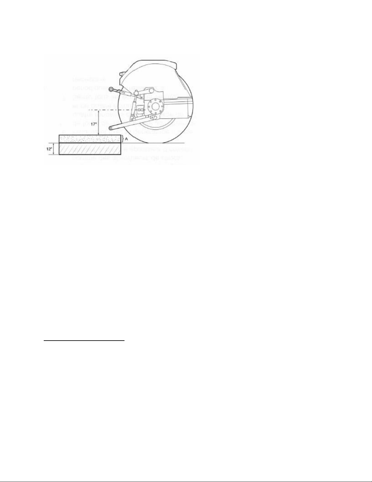
If the PTO is not mounted on a 3 point hitch or trailer: For safe operation the PTO
generator must be mounted onto a concrete slab with dimensions set forth in diagram
above.
Concrete slab construction
1. PTO generator mounting base (base
frame)
2. ½” masonry anchor bolt 8” long
3. Concrete slab
4. ½” thick rubber pad (will reduce
vibration)
5. ½” lock washer
6. ½” nut
IMD LLC_____________________________________________________ 11
10011-12 04/15
1. Choose a location and excavate the ground for a slab of the dimensions set forth in the
diagram above. Excavate at least one foot = 12 inches (30.4 cm) deep and frame above
ground sufficiently high enough that the height of the slab above the ground level is 17
inches (43.2 cm) below the centerline of the tractor’s PTO shaft (see dimension A in
the diagram above).
2. Reinforce with steel rods or steel grid or as otherwise recommended or required by
local building codes or applicable laws, to increase the strength and stability of the
concrete slab.
3. Pour the concrete and install four 1/2” x 8” masonry bolts according to the diagram
above.
4. Let the concrete cure until the slab has fully dried.
5. Install thick rubber pads for the generator mounting base to rest on. The pads, which act
as vibration absorbers, should be about ½” (1.27 cm) thick.
6. Install and secure PTO generator firmly using four ½” lock washers and four ½” – 13
nuts.
7. Tighten all nuts securely and check periodically and re-tighten as necessary.
Optional 3-point hitch
A 3-point hitch frame can be ordered from IMD if the PTO generator needs to be moved
frequently. This hitch frame will be connected to the tractor’s three-point hydraulic system
(see Accessories section page 27).
The hitch will be shipped disassembled. Basic tools are required for assembly.
Mounting the unit on the hitch frame and using the three-point attachment to the tractor
hydraulics makes the PTO generator secure against tipping over during power generation,
and yet allows it to be moved easily.

IMD LLC_____________________________________________________ 12
10011-12 04/15
Optional Heavy Duty Trailer
Using an IMD trailer is another option for increasing the stability and mobility of the PTO
generator (see Accessories section page 27).
Mounting the PTO generator on the trailer will give it sufficient stability so that it does not
tip over during service and also allows it to be easily moved from one location to another.
The trailer will be shipped disassembled. Basic tools are required for assembly.
Only use an IMD trailer or 3-point hitch that is specifically designed for mounting your
particular generator set, or the generator may tip during operation.
Electrical Installation
The generator is powerful enough to deliver a fatal electric shock. Extreme caution is
required.
All work on the power circuit and the electrical components must be carried out by an
experienced and licensed electrician.
Use only cables of the correct length, wire gauge and insulation depending on the
specific application.
Do not connect this generator to the electrical circuits of any house or building unless
an isolation switch has been installed by a licensed electrician according to the
manufacturer’s specifications and all applicable building codes and other laws and
regulations.
IMD LLC_____________________________________________________ 13
10011-12 04/15
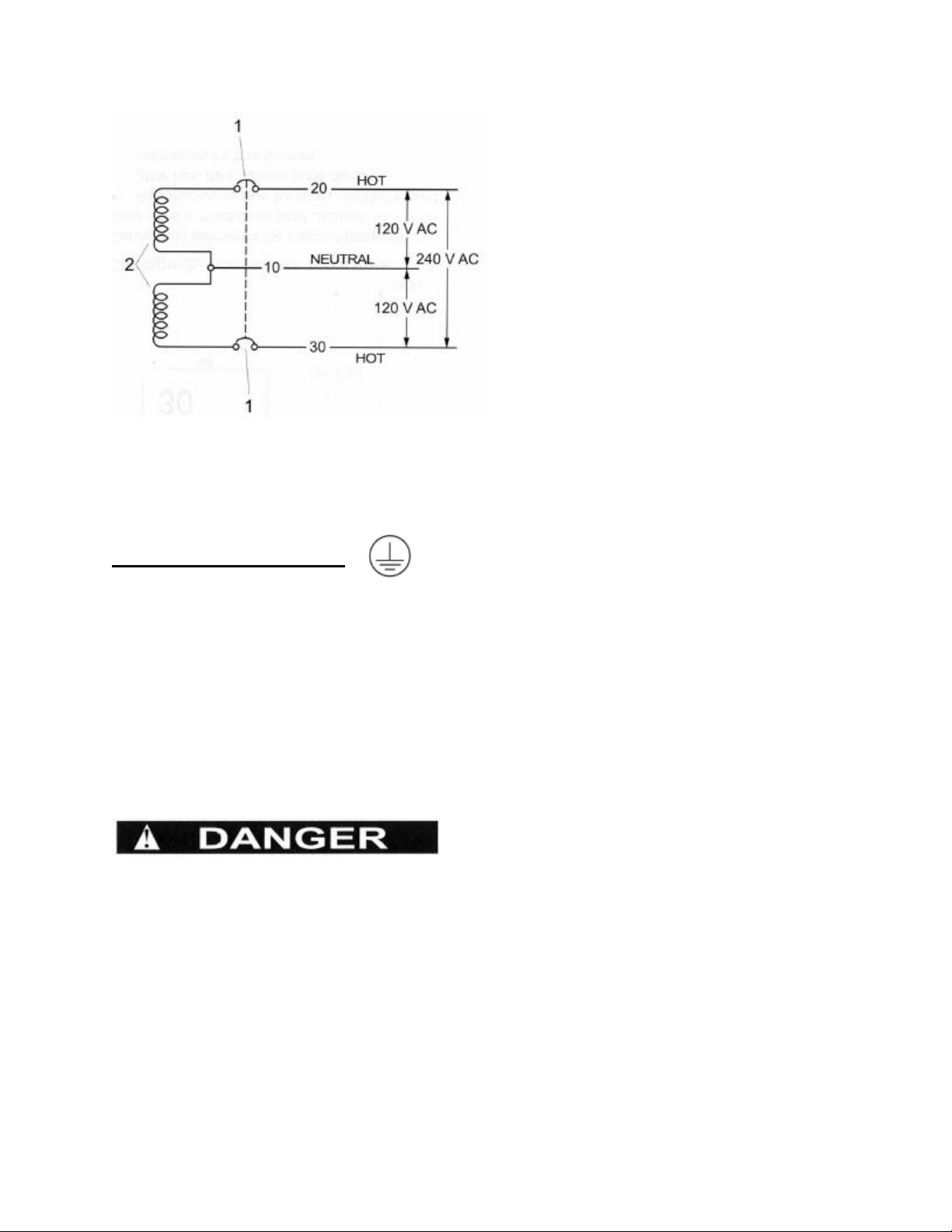
The generator employs a stator assembly having a dual set of AC power windings and a 3-
wire AC connection system. Each stator AC power winding supplies 120 volts AC. When
the two windings are connected in series, a 240 volt AC output results.
Grounding the generator
Make sure that the generator is properly grounded at all times!
Proper grounding of the generator will help prevent electric shock in the event of a ground
fault condition in the generator or in electrical devices connected to the generator.
Proper grounding also helps to dissipate static electricity, which often builds up in
ungrounded devices.
Do not connect the ground wire to any pipe that carries flammable or explosive
substances. Fire or an explosion may result.
The National Electrical Code requires that the frame and external electrically
conductive parts of this generator be properly connected to an approved earth ground.
Local electrical codes may also require proper grounding of generator.
However, local codes may vary widely. Consult with a local licensed and experienced
electrician for grounding requirements in your area.
Generator 3 wire AC Diagram
1. Main circuit breaker
2. Dual stator AC power windings
IMD LLC_____________________________________________________ 14
10011-12 04/15
Installing PTO shaft
If the guard for the power take-off shaft is not factory installed when the generator is
shipped:
The PTO shaft guard must be properly attached to the generator gearbox before the
generator is started up.
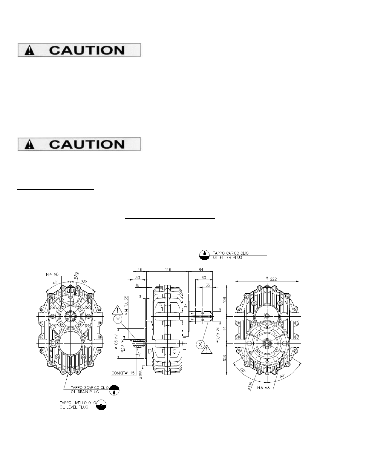
The PTO shaft end from the gearbox has a diameter of 1-3/8 inch and a 6-spline fitting
(6-spline drive shaft).
Push the PTO shaft onto the PTO shaft ends of the gearbox and tractor respectively,
and engage.
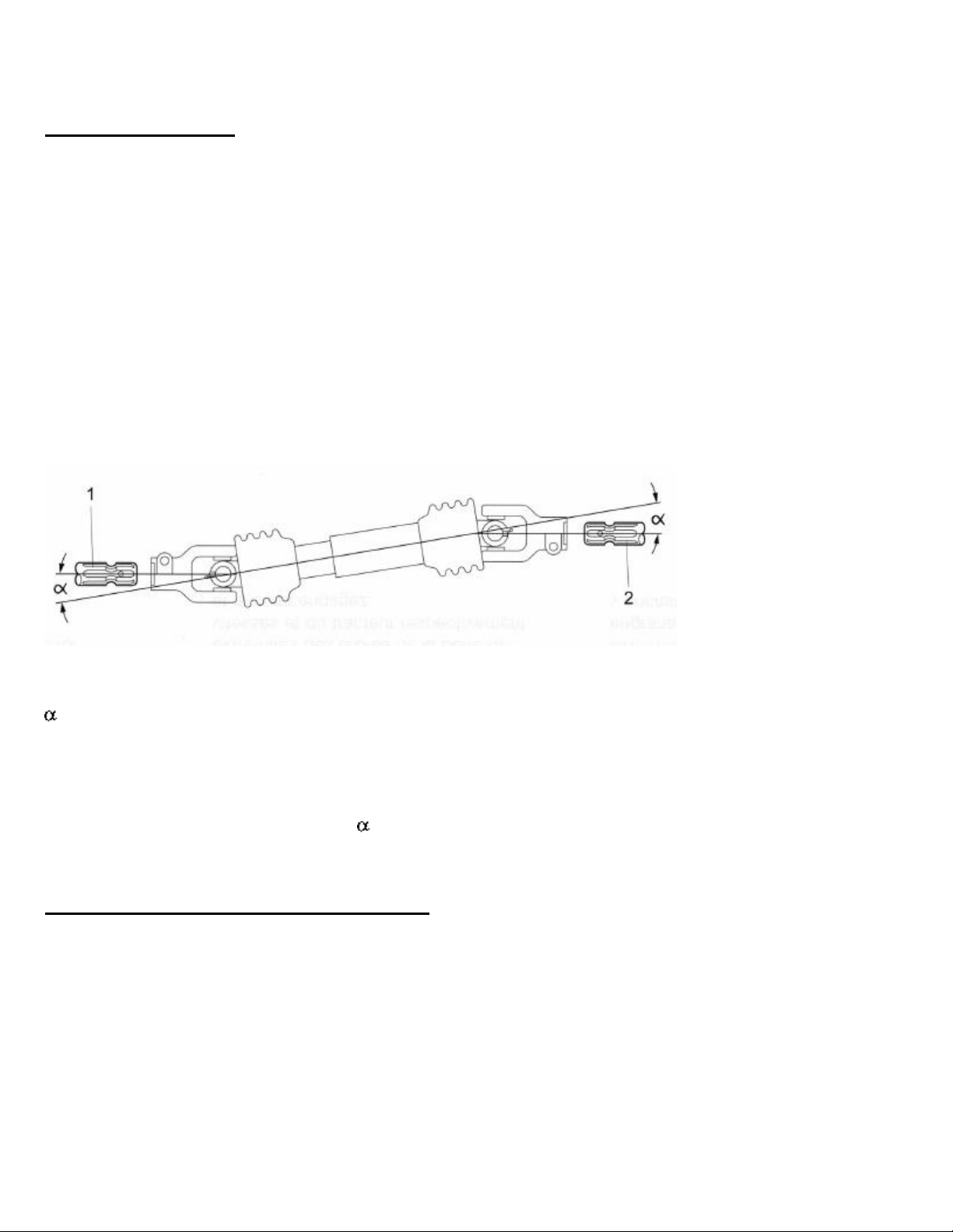
1 Generator PTO shaft end
2 Tractor PTO shaft end
PTO shaft joint angles
Keep generator PTO shaft end (1) and tractor PTO shafts (2) parallel as viewed from
above and from the sides of the shafts.
Maintain PTO shaft joint angles equal and as small as possible.
Checking the gearbox, oil level inspection
Be sure the gearbox is filled with the correct amount of gear oil before the generator is
used for the first time (see the “Maintenance section” for instructions).

IMD LLC_____________________________________________________ 15
10011-12 04/15
Operation
Switching ON
Check the following every time before use:
Is the generator securely attached to its concrete foundation or an approved device?
Is the generator properly grounded?
Are all safety devices fitted correctly?
Is the PTO shaft fitted correctly between the tractor and the generator?
Is there enough oil in the gearbox?
Have the power cords of all electrical loads been disconnected from the generator?
When operating stationary PTO-driven equipment, always apply the tractor parking brake,
and block the rear wheels on both sides in front and back with wedges or other appropriate
objects.
Starting the generator
Never start the generator with the main circuit breaker set to ON or closed position.
Plug in the desired electrical loads.
This may be done in the following ways:
1. Connect power cord set to the 120 Volt, 20 amp receptacles.
2. Connect power cord set to the 120/240 Volt, 50 amp receptacles.
Only run the generator at a PTO shaft speed of 540 rpm. Higher PTO shaft speeds will
damage the generator and may cause personal injury.
Start the tractor.
Set the PTO shaft lever to 540 rpm.
Only close circuit (turn breaker ON), when the panel frequency meter indicates 60 Hz.
If the frequency or the voltage is too low or high, adjust speed accordingly.
The correct operating frequency is 60 Hz.
Switch the main circuit breaker to ON or to the closed position.
Switch ON the electrical loads (e.g. appliances).

IMD LLC_____________________________________________________ 16
10011-12 04/15
The generator supplies its power to the electrical loads.
Check the frequency and/or Volt reading.
If the frequency and/or voltage have fallen below their correct operating range:
CAREFULLY Increase the tractor engine speed until the Hz meter indicates correct
range again.
Switching OFF
Turn OFF the electrical loads (appliances).
Set the generator Main Circuit Breaker to the OFF or OPEN position.
Let the generator and tractor engine run for a few minutes at no-load, to cool internal
parts.
Set the PTO shaft lever in the tractor to OFF.
Wait until the PTO shaft and generator have stopped moving and are stationary.
Switch off the tractor.
Disconnect and remove the PTO shaft.
Electrical connections can now be unplugged.
Maintenance, Cleaning, Care
Regular maintenance and cleaning are crucial for optimum performance and safe operation
of the generator.
Before starting maintenance and cleaning work:
Switch the main circuit breaker to OFF or to the opened position.
Disconnect and remove the PTO shaft
On completion of maintenance work:
Re-install all safety devices correctly

IMD LLC_____________________________________________________ 17
10011-12 04/15
Visual Inspection
Before switching on:
Check all components of the unit for visible external damage or leakage.
Check all electrical cables for loose contacts, broken insulations or signs of scorching
Functional test
After standing idle for long periods of time, the generator winding may corrode, reducing
the efficiency.
It is necessary to run the system regularly to ensure that the PTO generator will still
function properly in case of an emergency.
A monthly functional test is recommended for damp conditions.
A quarterly functional test is sufficient for dry conditions.
Regular operation of the system avoids:
1. Deterioration of the insulation resistance.
2. Build-up of deposits on the winding.
3. Corrosion.
4. Loss of performance.
Keeping the generator clean
The generator housing has openings for ventilation purposes. If dirt clogs these ventilation
openings the generator might overheat, get damaged and even catch fire. Dirt particles on
the hot surface of the generator might catch fire.
For these reasons the following precautions should be taken:
Keep the generator clean and free of foreign materials and objects.
In dustier environments frequent cleaning, even daily cleaning, may be necessary.
Remove dirt with compressed air (do not blow the dirt inside the generator) or a brush.
IMD LLC_____________________________________________________ 18
10011-12 04/15
Do not hose down the generator with water. Water can penetrate the generator stator and
rotor windings, which could reduce insulation resistance. Possible generator failure may
result.
Clean the interior of the generator control panel in extreme harsh environmental
conditions.
The voltage regulator and electrical terminals especially must be kept clean.
Check voltage regulator wires.
Make sure all circuit boards are fully plugged in to their receptacles.
Dirt and other deposits may form in loose connections and cause resistance and lack of
conductivity. These conditions, if not corrected by regular cleaning, may lead to a short
circuit and equipment failure.
Changing the gear oil
The generator is shipped from the factory without oil in the gearbox. It is therefore
necessary for the gearbox to be filled with the proper amount of gear oil:
27 ounces SAE90 gear oil
Drain the gear oil after the first 25 hours of use and refill with fresh oil as specified. Then
change after every 250 hours of use or every six months, whichever is earlier. After each
oil change, check that the correct amount of oil has been poured into the gearbox.**
Check Oil every 8 hrs: Oil level is correct if the lower edge of the inspection hole is nearly
covered with oil. **If your gearbox differs from the one above, contact IMD.
IMD LLC_____________________________________________________ 19
10011-12 04/15
Long-term storage
If the PTO generator is not used for a long period of time, do NOT store it outside or leave
it exposed to the elements.
The PTO generator should be stored in a dry clean environment protected from dust (e.g.
warehouse).
Observe the directions given for storage, because the air in barns may contain high levels
of moisture or high concentrations of dust, or sometimes aggressive gases (e.g. ammonia).
These factors result in an increased soiling of the generator and can lead to corrosion on
the alternator winding.
Before storing the PTO generator clean it thoroughly (see chapter Keeping the
generator clean).
For dust protection cover the PTO generator with a tarp while stored.
In order to keep the generator ready for emergency use, please make regular operation
checks (see chapter Functional Test).

IMD LLC_____________________________________________________ 20
10011-12 04/15
Technical specifications
Generator
PTO 10-2S Spec 10011-10012
Rated Maximum Cont. Wattage
10,000 watts
Power Factor
1
Rated AC Volts
120/240 V
Rated Maximum Load Current
80/40 A
Rated Frequency
60 Hz
PTO Power Needed (for rated output)
20 HP
PTO Drive Speed
540 RPM
PTO Shaft
1-3/8”,6-spline
Gearbox Reduction Type
Single stage
Gearbox Ration
1 to 6.66
Gearbox Oil
27 oz SAE 90
Approx. weight
156 lbs
Approx. dimensions l x w x h
26 x 9 x 16 inch
Receptacles
-Nema 14-50 R (120/240V 50A)
-Nema 5-20R duplex (120V 20A)
Circuit Breaker
-40 amps 2-pole
-20 amps 1-pole
Exploded view, alternator
1. Capacitor 25mF 450V (2pc) E140096 OR AVR BOARD (see below)
2. Rear grid P000069 Units with AVR:
3. Front grid (2pc) E130854 -AVR Board E140065
4. Electronic Kit P130856 -Fuse for AVR E140066
5. Fan (30mm) E130855
1
2
3
4
5
This manual suits for next models
2
Table of contents
Other IMD Portable Generator manuals

Popular Portable Generator manuals by other brands


Tektronix
Tektronix AWG510 Service manual

Generac Power Systems
Generac Power Systems 86640 Service manual

Champion Power Equipment
Champion Power Equipment 200972 quick start guide

Wallenstein
Wallenstein WHS12000 Operator's manual

Clarke
Clarke G900 Operation & maintenance instructions

Rato
Rato RV550 Service manual


