imenco SubVIS Orca II Subsea Camea User manual

SubVIS Orca II - User Manual
IMENCO AS Visiting Address: Stoltenberggata 1, 5527 Haugesund, Norway Office: +47 52 86 41 00 imenco@imenco.com
Org No: 923 005 749 MVA Mail Address: PO. Box 2143, 5504 Haugesund, Norway Fax: +47 52 86 41 01 www.imenco.com
1
SubVIS Orca II Subsea Camea
USER MANUAL
R1.0

SubVIS Orca II - User Manual
IMENCO AS Visiting Address: Kophaug 3, 5570 Aksdal, Norway Office: +47 52 86 41 00 imenc[email protected]
Org No: 923 005 749 MVA Mail Address: PO. Box 2143, 5504 Haugesund, Norway Fax: +47 52 86 41 01 www.imenco.com
2
Revision History
Rev.No
Description
Date of Rev
1.0
Issued for use
26.08.19
1.1
Standard connector changed
29.10.20
Contents
Contact.............................................................................................................................................................4
Warranty..........................................................................................................................................................4
1 General Description ................................................................................................................................5
1.1 Regarding these Instructions for Use.............................................................................................5
1.2 The SubVIS Orca II camera ..............................................................................................................5
1.3 Main Features...................................................................................................................................5
1.4 Definitions.........................................................................................................................................6
1.5 Typical use case................................................................................................................................6
1.5.1 Remote display and control station ........................................................................................7
2 Technical Specification............................................................................................................................8
3 Functional Description ............................................................................................................................9
3.1 Camera communication ..................................................................................................................9
3.1.1 Format of HTTP-API ............................................................................................................... 10
3.1.2 Video streaming..................................................................................................................... 10
3.2 Minimum Working Distance and Zoom ...................................................................................... 10
3.3 Cabling and Networking Hardware ............................................................................................. 11
3.4 Electrical Terminals inside the camera........................................................................................ 12
3.4.1 Power (always used) .............................................................................................................. 12
3.4.2 GPIO........................................................................................................................................ 13
3.4.3 RS232 ...................................................................................................................................... 13
3.4.4 RS485 ...................................................................................................................................... 13

SubVIS Orca II - User Manual
IMENCO AS Visiting Address: Kophaug 3, 5570 Aksdal, Norway Office: +47 52 86 41 00 imenc[email protected]
Org No: 923 005 749 MVA Mail Address: PO. Box 2143, 5504 Haugesund, Norway Fax: +47 52 86 41 01 www.imenco.com
3
4 Installation Instructions ....................................................................................................................... 15
4.1 Unpacking and testing.................................................................................................................. 15
4.2 Function test.................................................................................................................................. 15
4.3 Mechanical Installation................................................................................................................. 16
4.4 Electrical installation ..................................................................................................................... 16
4.4.1 Camera subsea connector .................................................................................................... 16
4.4.2 Subsea connector type and pin-out..................................................................................... 17
4.4.3 Connector and Cable to a host system................................................................................ 18
4.5 Adding the camera to a computer network................................................................................ 19
4.5.1 Quality of Service ................................................................................................................... 19
4.5.2 Network load and Data recording capacity ......................................................................... 19
4.5.3 Network address.................................................................................................................... 20
4.5.4 IP address discovery.............................................................................................................. 20
4.5.5 Multicast ................................................................................................................................. 20
4.5.6 Video streaming..................................................................................................................... 20
5 Operational Instructions...................................................................................................................... 21
5.1 Hazards and protective measures............................................................................................... 21
5.2 Over-temperature precautions.................................................................................................... 21
5.3 HTTP APIs....................................................................................................................................... 21
5.3.1 Temperature .......................................................................................................................... 21
5.3.2 Bandwidth setting.................................................................................................................. 21
6 Maintenance ......................................................................................................................................... 22
6.1 General maintenance ................................................................................................................... 22
6.2 Service and Repair ........................................................................................................................ 22
7 Packing & Shipping............................................................................................................................... 22
Appendix A, HTTP APIs ................................................................................................................................ 23
Appendix B, Dimension drawing ................................................................................................................ 24

SubVIS Orca II - User Manual
IMENCO AS Visiting Address: Kophaug 3, 5570 Aksdal, Norway Office: +47 52 86 41 00 imenc[email protected]
Org No: 923 005 749 MVA Mail Address: PO. Box 2143, 5504 Haugesund, Norway Fax: +47 52 86 41 01 www.imenco.com
4
Contact
for assistance / clarification on any of the contents of this manual, please contact:
Imenco AS
Subsea Electronics
Kophaug 3
5570 Aksdal NORWAY
Tel: +47 52 86 41 00
E-mail: electronics@imenco.com
www.imenco.co
Safety information
IMPORTANT! The Imenco SubVIS Orca II camera is a technically advanced product. Please make sure
to read and understand all sections of this manual before installing or operating this product.
Installation of this product should only be performed by qualified personnel.
WARNING! This product contains no user serviceable parts.
Do not open, alter or disassemble this product.
Failure to comply with this warning can result in damage to equipment and void of warranty. The
camera is filled with inert gas at manufacture.
WARNING!
The housing is NOT connected to any Protective Earth circuits.
The metal housing has no electrical contact with any of the circuits inside the camera. This is to
isolate the camera housing from other equipment that includes dangerous high voltage and to
minimize corrosion that otherwise might be intensified by electrical contact to other nearby metal
equipment or structures exposed to the sea water.
Warranty
Be sure to read and comply with Imenco’s Terms & Conditions that the SubVIS Orca II camera
product was sold under.

SubVIS Orca II - User Manual
IMENCO AS Visiting Address: Kophaug 3, 5570 Aksdal, Norway Office: +47 52 86 41 00 imenc[email protected]
Org No: 923 005 749 MVA Mail Address: PO. Box 2143, 5504 Haugesund, Norway Fax: +47 52 86 41 01 www.imenco.com
5
1General Description
1.1 Regarding these Instructions for Use
The intended use of these instructions is to provide and guide the operator/user of the equipment
with instructions on the technical specifics of the product, how it functions, the safety aspects of its
use, how to prepare, operate and maintain the product.
All information in this document is provided commercial in confidence and shall not be published or
disclosed, wholly or in part to any other party without Imenco’s written permission.
Copyright © 2019 IMENCO. All Rights Reserved.
1.2 The SubVIS Orca II camera
Figure 1, SubVIS Orca II camera
1.3 Main Features
•HD 1080p/60fps Video Streaming over Ethernet
•Low latency glass to glass: ≈100 ms
•Horizontal view angle 65° through a water corrected Fused Silica viewport
•HTTP protocol for configuration and control
•Embedded Computer “Imenco SmartBrain”
•Optional interfaces to peripherals: RS232, RS485, GPIO
View port
Camera
module
Imenco
Smart
Brain
Subsea
connector
Actual camera:
Camera block diagram:
DC power
Ethernet

SubVIS Orca II - User Manual
IMENCO AS Visiting Address: Kophaug 3, 5570 Aksdal, Norway Office: +47 52 86 41 00 imenc[email protected]
Org No: 923 005 749 MVA Mail Address: PO. Box 2143, 5504 Haugesund, Norway Fax: +47 52 86 41 01 www.imenco.com
6
1.4 Definitions
SubVIS
Subsea Visual Intelligence System
Orca II
This camera
SubVIS SmartBrain
Embedded computer included in Orca II
SmartView
Imenco software for control, viewing and recording of live
streaming video from up to four Imenco IP cameras
1.5 Typical use case
Figure 2, System example
Each camera in Figure 2 is connected to the rest of the world, for control and video streaming,
through a 1000BASE-T compliant cable. In a minimum system this cable could go directly to the
Network port of a suitable computer that has software (e.g. SmartView) installed for decoding and
using the received video.
The Ethernet communication of the two Orca IIs in Figure 2 are combined in a Switch and routed
through various other Networking hardware before connected to the client computer. Beware that
the network infrastructure and other network hosts between the Orca II camera and the Client
computer could potentially impose heavy traffic and delays in the video, which is unacceptable for
the operator. The installer must take measures to avoid that. The Orca II camera is designed to
Network Infrastructure
Network switch
Orca II
Light
100/1000 Mbps Ethernet
DC Power
100BASE-TX/1000BASE-T
Computer, Display and/or Data storage
Orca II

SubVIS Orca II - User Manual
IMENCO AS Visiting Address: Kophaug 3, 5570 Aksdal, Norway Office: +47 52 86 41 00 imenc[email protected]
Org No: 923 005 749 MVA Mail Address: PO. Box 2143, 5504 Haugesund, Norway Fax: +47 52 86 41 01 www.imenco.com
7
minimize latency in the video stream between the camera lens and the operator screen but cannot
compensate for delays that are introduced by other equipment in the network.
Figure 2 includes one computer display yet two cameras. The SmartView in its current version
supports streaming video from up to four cameras and can tile the display screen for live video
simultaneously from all.
The system could be configured with multiple computers receiving video from one single camera.
The Orca II camera itself is a live video stream server that can stream Unicast or Multicast and the
rest of the system is versatile Internet technology.
Cameras pinned out, on customer's request, with only 2 Ethernet pairs could encounter connection
problems when connected to Gigabit Ethernet switches. Appropriate settings must be altered in the
switches to accommodate for this.
1.5.1 Remote display and control station
Video Streaming and User Interface in the camera is realized with Internet protocols over Ethernet.
A computer with sufficient graphics performance and network interface can be used to operate and
view/record video from the Orca II camera.
Imenco provides “SmartView”; a software application that comes with basic control of the Orca II
camera, live video displaying, frame snapshots and video recording. Please refer to a separate
manual for the description of SmartView.

SubVIS Orca II - User Manual
IMENCO AS Visiting Address: Kophaug 3, 5570 Aksdal, Norway Office: +47 52 86 41 00 imenc[email protected]
Org No: 923 005 749 MVA Mail Address: PO. Box 2143, 5504 Haugesund, Norway Fax: +47 52 86 41 01 www.imenco.com
8
2Technical Specification
Weight
5.3 kg
Weight in sea water
3.7 kg
Greatest diameter
140 mm
Body diameter
117 mm
Length (excl. connector)
226 mm
Housing material
Titanium
View port material
Fused Silica
Connector
SubConn® DBCR13M + DLSA-M
(other connectors available)
Power input
24 VDC (18-75V), max 20 W
Maximum Depth
6 000 m sea water
Maximum internal temperatures
60°C
View Angle
Horizontal:
Diagonal:
64° in water
71° in water
Minimum Working Distance
(Increases, not linear, with Zoom)
0.1 m in water @ Zoom 1x
Video resolutions/frame rates
1080p@60/50/30/25
720p@60/50
576p@60/50/25
480p@60/50/30
Minimum Latency
≈100 ms
(Requires Low Latency mode and Frame Rate 60 fps)
Light sensitivity (High Sensitivity mode Off)
0,1 Lux
Communication & video interface
Ethernet 100BASE-TX / 1000BASE-T
Bitrate of encoded video stream
Configurable: 256 kbps to 40 Mbps
Recommended: >24 Mbps
Camera control protocols
HTTP
Video streaming protocols
RTSP/RTP, TCP/UDP, Unicast/Multicast
Video compression
H.264 AVC
Optical Zoom
30x
General purpose binary (0-5V) isolated IO
[Option] One input, one output and GND
RS232 isolated interface to peripherals
[Option] TxD, RxD, RTS#, CTS#, GND
RS485 isolated interface to peripherals
[Option] Half duplex or Full duplex

SubVIS Orca II - User Manual
IMENCO AS Visiting Address: Kophaug 3, 5570 Aksdal, Norway Office: +47 52 86 41 00 imenc[email protected]
Org No: 923 005 749 MVA Mail Address: PO. Box 2143, 5504 Haugesund, Norway Fax: +47 52 86 41 01 www.imenco.com
9
3Functional Description
3.1 Camera communication
Figure 3, Communication paths
The Smart Brain computer in the Orca II camera uses two communication paths of importance to the
operator: Real time video streaming from the Orca II and two-way control.
The video streaming features several configurations that should be set for optimal performance
adapted to the given installation.
The control communication is based on HTTP GET messages where the request is sent from the
Client computer and the response is sent in return from the Orca II camera.
The contents of a request and response are defined by Imenco as a “HTTP API”.
A range of such HTTP APIs are defined for the Orca II camera for various tasks such as configuring
the video streaming, controlling the video camera and system setup/monitoring.
Figure 3 shows the path of data related to HTTP APIs (Dashed lines in indigo color). Some of the
requests are directed to the Smart Brain itself while others are reshaped and forwarded to the video
camera module or even to optional external interfaces.
Digital video
RTSP or RTP
video stream
HTTP Get
Request / Response
Optional
RS232
RS485
GPIO
Camera control
UART/RS232

SubVIS Orca II - User Manual
IMENCO AS Visiting Address: Kophaug 3, 5570 Aksdal, Norway Office: +47 52 86 41 00 imenc[email protected]
Org No: 923 005 749 MVA Mail Address: PO. Box 2143, 5504 Haugesund, Norway Fax: +47 52 86 41 01 www.imenco.com
10
3.1.1 Format of HTTP-API
Each HTTP API defines a specific query part of the URL to the Orca II camera HTTP server.
The Client must send a HTTP GET request to the camera in this general format:
http://<IP address>/hsc?<query>
This could be entered in the address field of a Web browser and the Orca II camera would respond
with a message that would show up in the Browser window.
Here is an example of reading out an internal temperature from the camera
(assumed at address 192.168.1.2):
http://192.168.1.2/hsc?get_temperature=1
The HTTP GET Response would be a text string including the actual temperature in °C:
$31^
Some useful HTTP APIs are listed in APPENDIX A, HTTP APIS.
3.1.2 Video streaming
Streaming video can be received with a third party streaming media player such as VLC media player:
“rtsp://<Orca II IP address>:<port>/<name of video stream>
Note that such players may not be optimized for low latency.
Imenco’s SmartView is developed with lowest possible latency as a design requirement.
3.2 Minimum Working Distance and Zoom
Figure 4, Minimum Working Distances
1x
2x
3x

SubVIS Orca II - User Manual
IMENCO AS Visiting Address: Kophaug 3, 5570 Aksdal, Norway Office: +47 52 86 41 00 imenc[email protected]
Org No: 923 005 749 MVA Mail Address: PO. Box 2143, 5504 Haugesund, Norway Fax: +47 52 86 41 01 www.imenco.com
11
The camera needs to keep a minimum distance to be able to focus on an object. This is known as the
Minimum Working Distance and is measured from the front of the camera to the object.
Figure 4 illustrates the relationship between zoom and minimum working distance. The Minimum
Working Distance increases with Zoom so the object (green disk in the figure) has to be farther away
from the camera. (The figure is not to correct scale)
Figure 5, Minimum Working Distance vs Zoom
Figure 5 shows a crude graph of the Minimum Working Distance plotted versus Zoom values. Notice
that it grows rapidly above 6x and levels out above 10x to a maximum of 2.8 meter between the
camera and the object in water.
3.3 Cabling and Networking Hardware
The standard connector on the Orca II camera is from SubConn® Ethernet Series type Power
Ethernet Circular 13 pins.
Imenco offers customer specified connectors and cabling with the Orca II camera. Contact Imenco to
work out a solution for other than standard connectors.
The IEEE standards 100BASE-TX and 1000BASE-T defining 100Mb/s and 1000Mb/s data rates over
twisted pair copper cables recognize up to 100 m length between nodes. Pay special attention to the
choice of connectors, cable and method of wire termination in an actual Orca II installation and make
sure it performs to the above standards. Test the solution before committing to work.
The distance from the camera to the network port is usually just a few meters, such as when the
camera is installed on an ROV. The equipment behind that network port may include fiber optic
segments (through the umbilical of the ROV) that extend to the remote station on surface. Signal
transmission and networking hardware after the first network port is outside the scope of this

SubVIS Orca II - User Manual
IMENCO AS Visiting Address: Kophaug 3, 5570 Aksdal, Norway Office: +47 52 86 41 00 imenc[email protected]
Org No: 923 005 749 MVA Mail Address: PO. Box 2143, 5504 Haugesund, Norway Fax: +47 52 86 41 01 www.imenco.com
12
manual. This is left to qualified personnel who are competent to install, configure and diagnose
computer networks. Imenco does not support installation of such equipment.
3.4 Electrical Terminals inside the camera
NOTE: The Subsea connector is wired to these terminals when manufacturing the Camera. The
connector may not include sufficient number of conductors to cover all the terminals mentioned as
“Peripherals”.
3.4.1 Power (always used)
Name
Pin No
POWER IN N (0 V)
J12 PWR −
POWER IN P (24-48 VDC)
J12 PWR +
Table 1, Power terminals
The camera is powered by a DC voltage applied to the two power input terminals. The circuit
includes reverse polarity protection and the polarity must be correct for the camera to power up.
The camera housing is not connected to any conductor in the subsea connector or any terminal of
the electrical circuits inside the camera.
IMPORTANT! The camera housing is not connected to Protective Earth.
3.4.1.1
Ethernet (always used)
Transceiver ports:
RJ45:
1000BASE-T
100BASE-TX
Pin No
BI-DA +
Transmit +
1
BI-DA -
Transmit -
2
BI-DB +
Receive +
3
BI-DC +
4
BI-DC -
5
BI-DB -
Receive -
6
BI-DD +
7
BI-DD -
8
Table 2, Ethernet RJ45 Port
The Smart Brain includes an RJ45 port as in Table 2.
IMPORTANT! The Ethernet wiring must comply with IEEE 1000BASE-T all the way through subsea
connectors and cabling to the next network node.

SubVIS Orca II - User Manual
IMENCO AS Visiting Address: Kophaug 3, 5570 Aksdal, Norway Office: +47 52 86 41 00 imenc[email protected]
Org No: 923 005 749 MVA Mail Address: PO. Box 2143, 5504 Haugesund, Norway Fax: +47 52 86 41 01 www.imenco.com
13
3.4.1.2
Peripherals (optional)
Name
Pin No
Name
Pin No
RS232 RxD
J13-1
RS485 TxD-N (B)
J14-1
RS232 TxD
J13-2
RS485 TxD-P (A)
J14-2
RS232 CTS#
J13-3
RS485 RxD-N (B)
J14-3
RS232 RTS#
J13-4
RS485 RxD-P (A)
J14-4
GPIO IN (5V)
J13-5
GPIO OUT (5V)
J14-5
ISO GND
J13-6
ISO GND
J14-6
Table 3, Isolated RS232, RS485, GPIO
Table 3 includes some interfaces that all are galvanic isolated from the rest of the camera
electronics. All these share the same isolated ground which is present at two of the terminals.
The Orca II camera software includes HTTP APIs to read /write data over these interfaces. The RS232
and RS485 interfaces are however not used to control the Orca II camera functions.
Installation of the GPIO, RS232 and RS485 interfaces, if included in the Orca II camera subsea
connector, must be carried out by qualified personnel to avoid unreliable communication or
equipment failure.
3.4.2 GPIO
The two General Purpose Input/Output (GPIO) terminals operate at
levels nominally 5V or 0V with reference to ISO GND (digital ports that
are translated to logical high or low). The figure to the right shows the
output driver circuit of the GPIO Output.
A 1.69 k Ohm pull-up resistor limits the output current.
3.4.3 RS232
The RS232 interface includes the signals RxD, TxD, RTS# and CTS# all referenced to ISO GND.
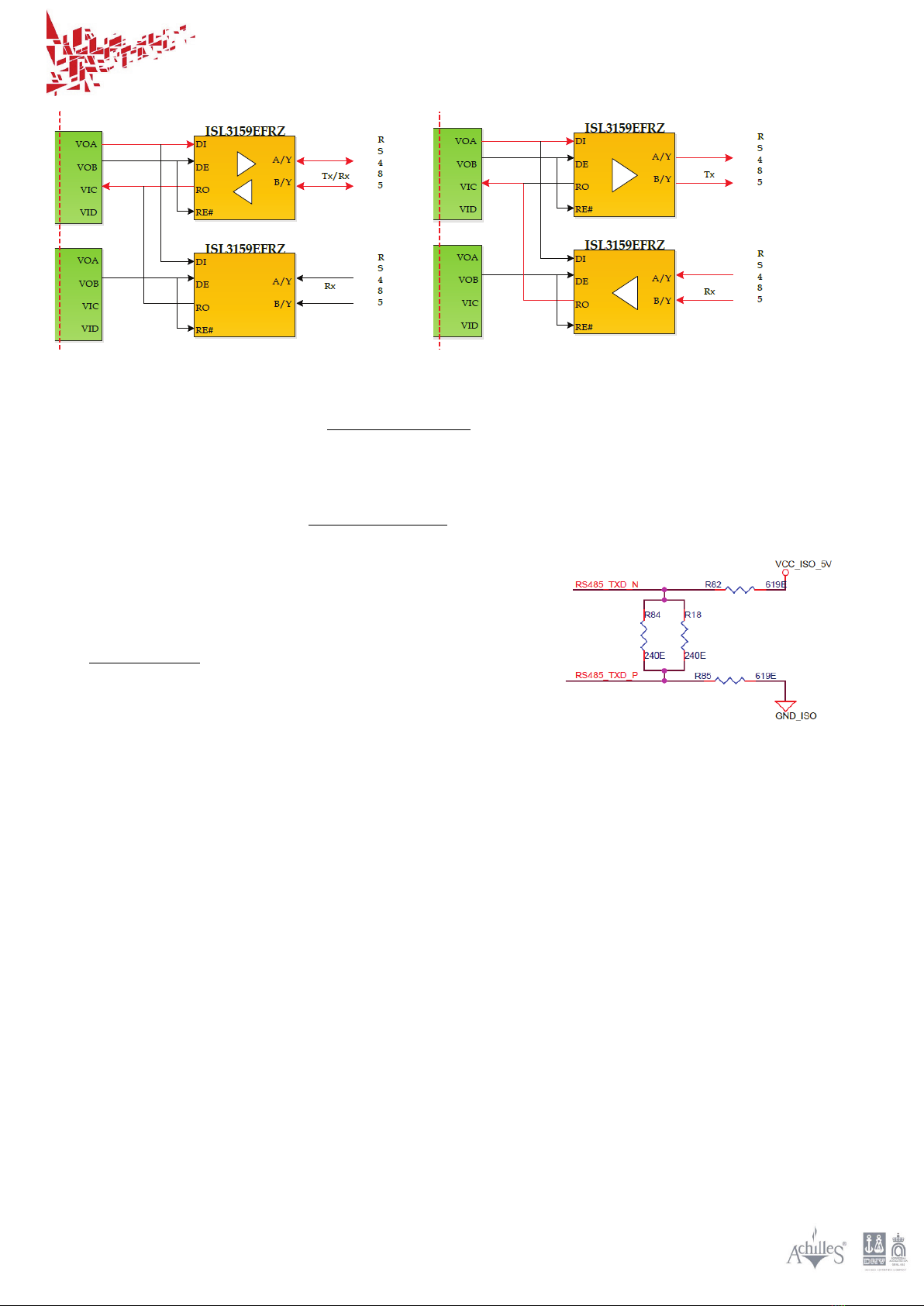
3.4.4 RS485
The RS485 interfaces include two Intersil® ISL3159E transceivers which enable the camera for either
Full duplex or Half duplex modes.
SubVIS Orca II - User Manual
IMENCO AS Visiting Address: Kophaug 3, 5570 Aksdal, Norway Office: +47 52 86 41 00 imenc[email protected]
Org No: 923 005 749 MVA Mail Address: PO. Box 2143, 5504 Haugesund, Norway Fax: +47 52 86 41 01 www.imenco.com
14
Figure 6, RS485 Half Duplex (left) and Full Duplex (right) modes
The left part of Figure 6 illustrates Half Duplex mode where the data path is highlighted with red
arrows. The bottom transceiver is not used in this mode, whereas the top transceiver alternates
between transmitting and receiving data.
The right half of Figure 6 shows Full Duplex mode with two transceivers in action. As indicated with
red arrows, the topmost takes care of transmitting and the bottom one receives data.
Each transceiver has an external 120 Ohm resistor across
terminals A and B (line termination resistor).
The Tx transceiver (topmost in Figure 6) has additional
resistors from A to VCC-ISO_5V and from B to GND_ISO as can
be seen in the figure to the right:

SubVIS Orca II - User Manual
IMENCO AS Visiting Address: Kophaug 3, 5570 Aksdal, Norway Office: +47 52 86 41 00 imenc[email protected]
Org No: 923 005 749 MVA Mail Address: PO. Box 2143, 5504 Haugesund, Norway Fax: +47 52 86 41 01 www.imenco.com
15
4Installation Instructions
Make sure that Imenco’s Terms & Conditions are followed when using this product.
4.1 Unpacking and testing
When having received the camera do a visual inspection for
damage of the packet or any of the parts.
The packet should include:
•Orca II camera
•User manual
•Memory stick with SmartView
•SmartView user manual
•Pressure test certificate
•Quality control certificate
•Optional test Cable
4.2 Function test
A preliminary function test should be performed prior to full scale installation. This is to familiarize
the user with the control functions and to verify that the system is fully operational after shipment.
Follow these steps to power up and check the proper functioning of the camera:
1) Acquire a cable that is terminated in one end with a connector compatible with the Orca II
camera connector as specified in 4.4.2 SUBSEA CONNECTOR TYPE AND PIN-OUT and the other end is
split into a Cat5e network cable with RJ45 termination for the computer as well as a DC-power
cable. Example of such cable is shown in FIGURE 9, MINIMAL TEST CABLE
2) Clear necessary space on your working desk and gather the
a. Orca II camera
b. Power supply providing DC anywhere between 24V and 48V and minimum 20W
c. Computer with SmartView installed
d. The test cable mentioned above
3) Do not power up the camera yet.
Lubricate the subsea connector as specified in section 6.1 and mate it properly.
4) Connect the network cable and start the computer.
5) Now turn on the DC power to the Orca II.
Indications that the Orca II has been properly powered up are:

SubVIS Orca II - User Manual
IMENCO AS Visiting Address: Kophaug 3, 5570 Aksdal, Norway Office: +47 52 86 41 00 imenc[email protected]
Org No: 923 005 749 MVA Mail Address: PO. Box 2143, 5504 Haugesund, Norway Fax: +47 52 86 41 01 www.imenco.com
16
a. The lens as seen through the front window moves back and then forward when the
video camera module powers up and initializes itself.
b. If an amp-meter is connected it should measure around 0.35A@48V or 0.7A@24V
6) Start SmartView and follow its instructions for use and connect to the camera.
7) Start streaming the video and check its quality and the camera control functions.
Understand that view angles in air are not as in water.
4.3 Mechanical Installation
Installation of this product should only be performed by qualified personnel.
Do not open the camera when carrying out the installation.
Mount the camera on a secure and vibration free surface and strap the cable for stress relief to the
supporting structure.
The camera should be electrically isolated from the mounting base in order to minimize any
corrosion current between the relatively noble Titanium housing of the camera and surrounding
metal structures.
A reference mark at the rear top of the camera housing can be used for alignment.
4.4 Electrical installation
IMPORTANT!
•Installation of this product should only be performed by qualified personnel.
•Verify that the connector pin assignments match with the system where the camera is being
installed. Mind the connector pin numbers and wire colors as necessary.
•Do not connect/disconnect the subsea connector when the power is ON.
4.4.1 Camera subsea connector
Imenco delivers the camera with a standard connector of type SubConn® DBH13M unless the
customer specifies otherwise. A connector & cable that has not been tested before should be verified
to meet all system specifications before the camera can be used.

SubVIS Orca II - User Manual
IMENCO AS Visiting Address: Kophaug 3, 5570 Aksdal, Norway Office: +47 52 86 41 00 imenc[email protected]
Org No: 923 005 749 MVA Mail Address: PO. Box 2143, 5504 Haugesund, Norway Fax: +47 52 86 41 01 www.imenco.com
17
4.4.2 Subsea connector type and pin-out
Figure 7, Orca II camera - standard connector and RJ45 plug with T568B colors
The Orca II camera standard subsea connector is SubConn® DBCR13M + DLSAM
The wires from this connector internally in the camera are color coded and connected to terminals of
the camera electronics as indicated in Table 4. The Ethernet twisted pairs are terminated according
to T568B as shown with an image of a RJ45 plug in Figure 7 and color names in Table 4.
Orca II camera
Internal electronics
SubConn® DBCR-13-M:
Terminal Description
Number
Internal Wire color
Conductor
Power in Minus
J12 PWR −
Black
1
DC Power
Not connected
Orange (screen)
2
Power in Plus
J12 PWR +
White
3
BI-DA + / Transmit +
RJ45-1
White/Orange
9
Twisted
pairs
T568B
color
scheme
BI-DA - / Transmit -
RJ45-2
Orange
8
BI-DB + / Receive +
RJ45-3
White/Green
11
BI-DC +
RJ45-4
Blue
6
BI-DC -
RJ45-5
White/Blue
7
BI-DB - / Receive -
RJ45-6
Green
10
BI-DD +
RJ45-7
White/Brown
5
BI-DD -
RJ45-8
Brown
4
RS232 TxD *
J13-2
Red
12
Optional
use
RS232 GND *
J13-6
Green
13
Table 4, Orca II camera standard subsea connector pinout (Ethernet connected as T568B)
The Orca II camera is powered by an adequate DC source (24 V, minimum 20W)connected with
polarity and pin numbers as indicated in Table 4.
*) The galvanic isolated RS232 output is optional and could be replaced with RS485 or GPIO(0-5V).

SubVIS Orca II - User Manual
IMENCO AS Visiting Address: Kophaug 3, 5570 Aksdal, Norway Office: +47 52 86 41 00 imenc[email protected]
Org No: 923 005 749 MVA Mail Address: PO. Box 2143, 5504 Haugesund, Norway Fax: +47 52 86 41 01 www.imenco.com
18
4.4.3 Connector and Cable to a host system
Figure 8, Cable and connector
The SubConn® range includes a cable that has been successfully used with the Orca II camera:
The product name is: D-P-P4TP24#4C18#
Its cross section view is presented in FIGURE 8, Suggested cable and connector and some
characteristics from the datasheet are: Diameter 14 mm, Blue polyurethane jacket, minimum
bending radius 130 mm, maximum depth 6000 m.
MacArtney specify that SubConn® Ethernet series connectors and cables are capable of data
transfer rates up to 1Gbit/s over 75 m.
The connector compatible with the Orca II standard connector is pictured also in FIGURE 8, Suggested
cable and connector. Some characteristic are: Chloroprene rubber, sockets gold plated brass, pins in
gold plated beryllium copper. Locking sleeves are Red POM.
Inquire a Subconn® sales contact for current details and parts availability.
Figure 9, Minimal test cable
A short cable direct to the computer can come in handy for testing and configuration of an Orca II
system. The cable in FIGURE 9, Minimal test cable has a Power input plug and a RJ45 plug for the
computer network port.

SubVIS Orca II - User Manual
IMENCO AS Visiting Address: Kophaug 3, 5570 Aksdal, Norway Office: +47 52 86 41 00 imenc[email protected]
Org No: 923 005 749 MVA Mail Address: PO. Box 2143, 5504 Haugesund, Norway Fax: +47 52 86 41 01 www.imenco.com
19
Notice that this one has a black Locking Sleeve which was found to be not quite secure when mixed
with the original Locking Sleeve from SubConn showed in FIGURE 7.
4.5 Adding the camera to a computer network
The camera must be connected to a computer that functions as the remote control and video
viewing station.
4.5.1 Quality of Service
The latency that has been specified is based on a reasonable Quality of Service, through the network
from end to end, so that the video data packets get transmitted according to their priority. If the
network is congested and includes suboptimal network hardware, then the latency beyond the
specified max delay may be experienced.
4.5.2 Network load and Data recording capacity
The camera will load the network with a significant stream of data as long as the video is streaming.
Adding multiple cameras will add to this stream. The network administrator should check that the
network has sufficient capacity for the number of cameras that are added, considering the bitrate
setting of each camera.
Resolution
Framerate
Quality
Storage
Low
Typical
High
Min/Max
Typical
PAL/NTSC
25p/30p
1
3
8
0.5 - 3.6
1.3
PAL/NTSC
50i/60i
2
3.5
8
0.9 - 3.6
1.5
720p
25p/30p
2.5
6
15
1.1 - 6.6
2.6
720p
50p/60p
3
8
24
1.3 - 10.6
3.6
1080p
25p/30p
5
15
24
2.2 – 10.6
6.6
1080p
50i/60i
8
15
24
3.6 – 10.6
6.6
1080p
50p/60p
10
24
28
4.4 – 12.3
8.8
All quality rates in Mbit/sec, storage in GByte/hour
Table 5, Data rates and storage size
The camera bandwidth consumption can be reduced by lowering the demand for picture quality.
This is done by sending a control message to the camera as explained in the camera operation
section.
The bandwidth consumption will vary slightly by the variation of information in the image. A still
image results in less data traffic than one with many variations in details and colors and when the
camera or objects in the picture is moving. This is the nature of the video compression.
The recommended bandwidth for each camera is minimum 24 MBits/s for 1080p/60

SubVIS Orca II - User Manual
IMENCO AS Visiting Address: Kophaug 3, 5570 Aksdal, Norway Office: +47 52 86 41 00 imenc[email protected]
Org No: 923 005 749 MVA Mail Address: PO. Box 2143, 5504 Haugesund, Norway Fax: +47 52 86 41 01 www.imenco.com
20
4.5.3 Network address
The camera can obtain its network address automatically through DHCP, but the client that wants to
connect to the camera may have difficulty to find which address the camera was assigned.
If the camera is connected to the DHCP service in a private network, then its host number (xxx, yyy in
this table) will be unknown for a potential camera client on the same network:
10.
0-255.
xxx.
yyy
172.
16-31.
xxx.
yyy
192.
168.
xxx.
yyy
The default setting of the camera is therefore a fixed network address selected by the user.
The fixed network address configuration of one device is not recommended in a DHCP controlled
network since it can cause address conflicts with other devices on the same network.
Running the camera on your office network is not advised because of the large and constant data
output. The intended use of the Orca II camera is to assign each camera a fixed network address
within a closed network.
4.5.4 IP address discovery
The camera includes a feature for clients to discover its address. The camera is listening to multicast
group 224.73.xx.xx, port <yyy> and looks for “IMCN_ENQ” in the 8 byte header received on that port.
On having received one such message the camera will output a response message to the same
group and port containing its name and identities as well as it current IPv4 address.
Contact Imenco for details on this feature.
The SmartView can detect cameras on the network using this mechanism.
4.5.5 Multicast
Video streaming is set to multicast mode by default. Some older network hardware might not
support this. The camera can be set to stream the video in unicast mode.
4.5.6 Video streaming
The protocols involved are RTSP, RTP and RTCP. The bulk of video data is sent in the RTP protocol.
Streaming can be started without using the session control protocol RTSP when the client has prior
knowledge of the camera details.
Table of contents
Other imenco Digital Camera manuals

Popular Digital Camera manuals by other brands


Eickemeyer
Eickemeyer EICKVIEW user manual

CIS
CIS VCC-5CL1M Product specification & operational manual

Panasonic
Panasonic LUMIX DMC-FS12 operating instructions

Canon
Canon Powershot SD1400 IS user guide

Canon
Canon Leather Soft Case 70 Advanced user's guide

GoPro
GoPro Hero 5 Motorsports HERO Wide instructions


