IMI Hydronic TA-SCOPE User manual

310 297-02 EN
08.2017
TA-SCOPE


TA-SCOPE
3
Contents
End User License Agreement.......................................................................................................................5
Introduction .................................................................................................................................................7
Instrument and Measuring Equipment..........................................................................................................8
Guide to Manual and Instrument..................................................................................................................9
Handheld 9
Abbreviations 9
Display and Keypad...................................................................................................................................10
Handheld...................................................................................................................................................10
Display Information Bar Icons 10
Keypad Keypad Icons 10
Functional Contents 11
DpS-Visio ..................................................................................................................................................12
Measuring Preparations .............................................................................................................................14
Prerequisites for Balancing with TA-SCOPE 14
Switch on/off the units 14
Wireless Communication 14
Connect / Disconnect Measuring Equipment 15
Calibration of Dp Sensor 16
Handwheel 16
Connections for Cables 16
Hydronic Functions....................................................................................................................................17
Quick Measure ..........................................................................................................................................18
Measure Flow 18
View Saved Measurements 19
Flow Adjustment – Computer Method 19
Measure Differential Pressure (∆p) 20
Measure Temperature 20
Measure Power 21
Hydronic Networks ....................................................................................................................................23
Navigate Hydronic Networks 23
Edit Existing Network 23
Delete Network 24
Create a Hydronic Network 24
Balancing...................................................................................................................................................25
Balance a Hydronic Network with TA-Diagnostic 25
Balance a Hydronic Network with TA-Wireless 26
Modify or Define New Module 28
Troubleshooting .........................................................................................................................................29
Diagnose a Hydronic Network with TA-Diagnostic 29
Use the Required Dp on Circuit Troubleshooting Wizard 29
Data Logging.............................................................................................................................................30
Start a New Logging 30
Download Loggings 31
View Loggings 31
Support Functions .....................................................................................................................................33
Fluid ..........................................................................................................................................................34
Change Fluid 34
Hydronic Calculator ...................................................................................................................................35
Calculate Flow/Kv/Dp (∆p)/Power/DT (∆T) 35
Calculate Valve Opening 35
Recommend Pipe Dimension 35
Recommend Valve Dimension 36
Unit Conversion 36
Contents

TA-SCOPE
4
Settings .....................................................................................................................................................37
Information ................................................................................................................................................39
PC Communication ...................................................................................................................................40
Transfer of Data 40
Software Upgrade 40
Instrument Care and Service......................................................................................................................41
Batteries – Capacity & Charging 41
Filter Cleaning 42
Calibration Certificates 42
Guarantee..................................................................................................................................................43
FCC Notification and ETL Markings ...........................................................................................................44
Technical Specifications .............................................................................................................................45
Accessories ...............................................................................................................................................46
Note! The products, texts, photographs, graphics and diagrams in this brochure may be subject to alteration by
IMI Hydronic Engineering without prior notice or reasons being given. For the most up to date information about
our products and specifications, please visit www.imi-hydronic.com.
IMI Hydronic Engineering AB, 524 80 Ljung, Sweden.
!
TA-SCOPE includes software licensed from OMRON SOFTWARE Co., Ltd.
Advanced Wnn©OMRON SOFTWARE Co., Ltd. 2002 – 2010.
All rights reserved.
Contents
Warning! Beware of hot fluid in the valve. Always follow the sequence described in the manual
when connecting and disconnecting the measuring equipment.
!
Water temperature over 52°C (125°F) can cause severe burns instantly or death from scalds. Always consider
the risks of injury from hot water before starting any measurement on a heating system and follow relevant local
legislation, regulations, standards and good industry practice for working with pressurised hot water systems.
Always use appropriate personal safety equipment when working on a heating system. Examples of appropriate
safety equipment include (but are not limited to) a face shield, heat resistant rubber gloves and boots and a long
sleeved apron (long enough to cover the tops of the boots). Always wear your boots inside your trouser legs to
prevent/minimise any hot water flowing into your boots. IMI Hydronic Engineering will not take any responsibility
for injury howsoever caused by hot water during measurement.
Warning! The surface on the Dp Sensor can be hot while measuring on hot media.
Always use suitable safety equipment.
!
Warning! Both Handheld and Dp Sensor contain batteries which require charging. The supplied
multi-charger from IMI Hydronic Engineering must be used!
Warning! Do not open the instrument. This can damage the instrument and void your guarantee!
See page 43 for further information.
!
!
CAUTION! Read the user manual before using the product.
!

TA-SCOPE
5
End User License Agreement
By using TA-SCOPE or the Software, you acknowledge that you have read this agreement (“Agreement”),
understood the content of it and agree to be bound by the terms of this Agreement. If you do not agree to the
terms of this Agreement, you are not permitted to use TA-SCOPE or the Software.
This Agreement is entered into between IMI Hydronic Engineering and the “End User”.
1. Definitions
“Documentation” means the manual, the tutorial and other materials related to the Software, provided to the End
User.
“End User” means any person or company who is entitled to use the Software according to this Agreement.
“Software” means the software, Documentation, including any updates and upgrade thereto, for the TA-SCOPE
which is provided to an End User under this Agreement.
“TA-SCOPE” means the instrument manufactured and sold by IMI Hydronic Engineering used for hydronic
balancing and troubleshooting of HVAC systems, currently named TA-SCOPE.
2. License grant
2.1 Subject to the terms and conditions set forth in this Agreement and the payment of all applicable fees
charged by IMI Hydronic Engineering for TA-SCOPE, IMI Hydronic Engineering grants End User a non-exclusive,
non-transferrable license to use the Software on a single TA-SCOPE devise, provided however that this
Agreement does not grant End User any title or right of ownership in or to the Software.
2.2 The Software shall be used only for End User’s own computing requirements in accordance with the terms and
conditions set forth herein, and only in combination with the TA-SCOPE.
3. Restricted use
3.1 End User shall not use the Software for any purposes other than the use specified in Section 2.2.
3.2 End User shall not make, have made or permit its employees or third parties to make, any copies or
verbal or media translations of the Software, in whole or part, for any reason. End User shall not use or allow the
Software to be used, directly or indirectly, in any manner that would enable any person or entity to copy or use the
Software or part thereof.
3.3 End User shall not use the Software on any TA-SCOPE that End User does not own or control, and End
User may not distribute or make the Software available to any third party. End User may not assign, transfer, rent,
lease, lend, sell, redistribute or sublicense the Software.
3.4 In case End User permanently transfers all of its rights to the TA-SCOPE device, End User may include
the license granted hereunder in such transfer, provided, however, that End User retains no copies of the
Software, End User transfers all of the Software (including all component parts, the media and printed materials,
any upgrades, all platforms, this Agreement, the serial numbers, and, if applicable, all other software products
provided together with the Software), and End User ensures the recipient to agree and be bound by the terms of
this Agreement.
3.5 END USER SHALL NOT MODIFY, DISASSEMBLE, DECOMPILE, RECREATE OR GENERATE ANY
SOFTWARE OR ANY PORTION OR VERSION THEREOF UNLESS AND TO THE EXTENT PERMITTED UNDER
APPLICABLE MANDATORY LAW.
3.6 End User shall not remove, erase or hide from view any copyright, trademark, confidentiality notice, mark or
legend appearing on TA-SCOPE or in the Software or any form of output produced by the Software.
3.7 IMI Hydronic Engineering reserves its right to continuously without notification: (i) verify the validity of each
license used by an End User; (ii) evaluate the Software; and (iii) to automatically update the Software.
End User License Agreement

TA-SCOPE
6
4. No warranties
4.1 THE SOFTWARE IS PROVIDED “AS IS” WITH NO WARRANTIES WHATSOEVER. IMI HYDRONIC
ENGINEERING DOES NOT, EITHER EXPRESSED, IMPLIED OR STATUTORY, MAKE ANY WARRANTIES,
CLAIMS OR REPRESENTATIONS WITH RESPECT TO THE SOFTWARE, INCLUDING, WITHOUT LIMITATION,
WARRANTIES OR CONDITIONS OF QUALITY, PERFORMANCE, NON-INFRINGEMENT, MERCHANTABILITY,
OR FITNESS FOR USE FOR A PARTICULAR PURPOSE. IMI HYDRONIC ENGINEERING FURTHER DOES
NOT REPRESENT OR WARRANT THAT THE SOFTWARE WILL ALWAYS BE AVAILABLE, ACCESSIBLE,
UNINTERRUPTED, TIMELY, SECURE, ACCURATE, COMPLETE AND ERROR-FREE.
4.2 THE ENTIRE RISK ARISING OUT OF THE USE OR PERFORMANCE OF THE SOFTWARE REMAINS WITH
END USER, E.G. END USER ASSUMES FULL RESPONSIBILITY FOR ITS USE OF THE SOFTWARE AND ANY
INFORMATION ENTERED, USED AND STORED THEREON. END USER ASSUMES FULL RESPONSIBILITY FOR
ENSURING THAT DATA IS NOT INADVERTENTLY MODIFIED, DELETED, DESTROYED OR DISCLOSED.
4.3 TO THE EXTENT NOT PROHIBITED BY APPLICABLE LAW, IN NO EVENT SHALL IMI HYDRONIC
ENGINEERING BE LIABLE FOR ANY PRODUCT LIABILITY, LOSS OF OR DAMAGE TO REVENUES, PROFITS
OR GOODWILL OR OTHER SPECIAL, INCIDENTAL, INDIRECT OR CONSEQUENTIAL DAMAGES OF ANY KIND,
RESULTING FROM IMI HYDRONIC ENGINEERING’S PERFORMANCE OR FAILURE TO PERFORM PURSUANT
TO THE TERMS OF THIS AGREEMENT, OR RESULTING FROM THE FURNISHING, PERFORMANCE, OR
USE OR LOSS OF USE, LOSS OF DATA OR LOSS OF ANY SOFTWARE OR OTHER MATERIALS DELIVERED,
INCLUDING, WITHOUT LIMITATION, ANY INTERRUPTION OF BUSINESS, EVEN IF END USER HAS BEEN
ADVISED OF THE POSSIBILITY OF SUCH DAMAGES.
5. Intellectual Property rights
5.1 IMI Hydronic Engineering is the owner of all copyright, trademarks, patents, trade secrets and any other
intellectual property rights which subsist in or relate to the Software and these properties shall always remain
vested in IMI Hydronic Engineering.
5.2 Nothing in this Agreement shall be construed as a sale of the Software. Any and all rights not expressly
granted by this Agreement to the End User are reserved by IMI Hydronic Engineering.
6. Term and termination
6.1 The license granted hereunder shall commence upon the execution of the agreement between IMI Hydronic
Engineering and the End User’s acceptance of the terms and conditions herein contained, and shall continue in
effect unless terminated earlier pursuant hereto.
6.2 The license granted hereunder is effective until terminated by End User or IMI Hydronic Engineering. IMI
Hydronic Engineering has the right to terminate the Agreement immediately if End User fails to comply with any
term of this Agreement. Upon termination of the Agreement, End User shall cease all use of the Software, and
destroy all copies, full or partial, thereof.
7. Disputes and governing law
7.1 Any dispute, controversy or claim arising out of, or in connection with, this Agreement, or the breach,
termination or invalidity thereof, shall be finally settled by arbitration administered by the Arbitration Institute of
the Stockholm Chamber of Commerce. The Rules for Expedited Arbitrations of the Arbitration Institute of the
Stockholm Chamber of Commerce shall apply, unless the institute – taking into account the complexity of the
case, the amount in dispute and other circumstances – determines, in its discretion, that the Arbitration Rules of
the Arbitration Institute of the Stockholm Chamber of Commerce shall apply. In the latter case, the institute shall
also decide whether the arbitral tribunal shall be composed of one or three arbitrators. The seat of arbitration shall
be Gothenburg, Sweden. The language of the arbitration shall be English.
7.2 This Agreement shall be governed by and construed in accordance with the laws of Sweden, excluding its
conflict of laws principles providing for the application of the laws of any other jurisdiction.
End User License Agreement

TA-SCOPE
7
Introduction
TA-SCOPE is a tough, effective balancing instrument for accurate measuring and documenting of differential
pressure (∆p), flow, temperature and power in hydronic systems.
Wireless functionality and an easy-to-use interface ensure quicker and more cost-efficient balancing and trouble
shooting.
TA-SCOPE links effortlessly to the PC software – HySelect – gaining the maximum benefit from recorded data and
enabling professional report writing and automatic software upgrades.
TA-SCOPE consists of two main components:
Handheld unit – computer based unit programmed with the IMI TA valve characteristics. Straightforward functions
with easy-to-follow instructions on the colour display.
Differential Pressure Sensor unit – the DpS-Visio communicates wirelessly with the Handheld and has an OLED
display for showing its status, measured data and other information.
Introduction

TA-SCOPE
8
Instrument and Measuring Equipment
23 24 25 26 27
1 Handheld unit (Hh)
2 Dp Sensor unit (DpS-Visio)
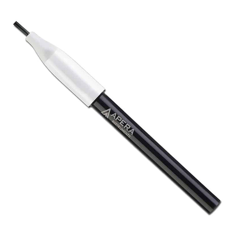
3 Digital Temperature Sensor (DTS)
4 Measuring hoses, 500 mm, red/blue
5 Safety pressure and temperature probe
(SPTP)
6 Safety pressure probes (SPP)
7 Measuring hoses with twin needle,
150 mm
8 Flashlight
9 Mirror
10 Chucks for older valves, red/blue
11 Allen Keys 3 mm/5 mm
12 Spanner for measuring points on older
valves
13 Presetting tool TBV-C,-CM, (-CMP)
14 Spare filters (4 pcs)
15 Chain for mounting
16 Neckstrap
17 USB-cables for connection;
A. Hh-PC
B. Hh-DpS-Visio / PC - DpS-Visio
18 Multi-charger for Handheld, Dp Sensor(s)
and TA-SCOPE Relays
19 DC cables (2 pcs; 1 Ø2,35 for Hh,
1 micro USB for DpS-Visio)
20 AC cable (EU, UK, US or AU/NZ)
21 Cable wrapping
22 Case
23 USB stick with manual and HySelect
software
24 Calibration certificates for DpS-Visio,
DTS and SPTP
25 Quick Guide
26 SPTP/SPP stickers
27 Guarantee/Service/Calibration form
Instrument and Measuring Equipment

TA-SCOPE
9
Guide to Manual and Instrument
Guide to Manual and Instrument
General Instrument Instructions
TA-SCOPE facilitates effortless performance of all hydronic functions through easy to navigate menus.
Handheld
The display is divided into three areas, the Information bar, the Main display and the Function keys.
1 – Information bar
Icons on the Information bar display details of battery status, connection type and
intensity.
2 – Main display
Instructions on how to carry out hydronic functions are shown on the Main display.
3 – Function keys
The three top keys on the key board are used for selecting options shown in the lower
part of the Main display. The options vary depending on which menu is currently shown.
Keypad
• The keypad has alphanumeric keys. Select a letter by repeatedly pressing the key
until the desired letter appears. Prolonged press enters a digit.
• Dot key works as caps lock. For a dot keep the key pressed until a dot appears.
• The zero key works as a space bar.
Entering Information in Menus
• When entering values to an input field in a menu, navigate to the desired row and start typing.
• Cycle the options in the input fields.
• Change units from the menu for any of the hydronic functions by navigating to the desired row and cycle
the units.
• Increase/decrease values like valve size, time, date direct from the input field by cycling the options.
• To prevent entering a too high or too low value TA-SCOPE automatically corrects values in the input fields. The
maximum/minimum value will appear in red, accompanied by a beep.
Tips! The numbers 1-9 can be used to shortcut the menus in the main display.
!
Special Menu Features
If multiple temperature sensors are connected when measuring, cycle the
sensors by navigating to the temperature row and press enter. An icon
on the display indicates which of the sensor is currently showing temperature
reading.
The temperature to be considered for fluid properties can be taken either from
one of the connected temperature sensors or from direct input in the fluid
screen. Navigate to the icon beside the fluid field and press enter to cycle
amongst the available options.
Abbreviations
Hh Handheld unit
DpS-Visio Differential Pressure Sensor unit
DTS Digital Temperature Sensor
SPTP Safety Pressure and Temperature Probe
SPP Safety Pressure Probe
Dp / ∆p Differential Pressure
DT / ∆T Differential Temperature
q Flow
P Power
T Temperature

TA-SCOPE
10
Display and Keypad
Handheld
Display Information Bar Icons
Keypad Keypad Icons
Information Bar Icons
Keyboard Icons
Function key
Options depend on text in display
On/Off
Flow adjustment (Computer method)
Short cut button
Return/Escape
Enter
Navigation up/down
Navigation right/left
Alphanumeric
0-9, A-Z plus symbols
Battery status bar
Charging of battery
Battery symbol
Handheld
Dp sensor DpS-Visio
Wireless communication
Intensity of wireless signal
Wireless signal set to Off
Connection by cable
Dp sensor (older version)
Display and Keypad

TA-SCOPE
11
Functional Contents
Quick Measure
Page 18
Measure Flow
Measure Differential Pressure (∆p)
Measure Temperature
Measure Power
View Saved Measurements
Hydronic Networks
Page 23
Navigate Hydronic Networks
Add New Network
Edit Network
Delete Network
Measure, Balance & Log Functionality
Balancing
Page 25
Prerequisites for Balancing
Balance a Hydronic Network with TA-Diagnostic
Balance a Hydronic Network with TA-Wireless
Modify or Define New Module
Troubleshooting
Page 29
Diagnose a Hydronic Network with TA-Diagnostic
Use the Required Dp on Circuit Troubleshooting Wizard
Data Logging
Page 30
Set Parameters for Logging
Perform Logging
Download logging from Dp Sensor
View Loggings in Handheld
Display Logging as Graph/List
Fluid
Page 34
Fluid Type
Temperature
Select Additive
Additive Concentration
Define Other Fluid
Hydronic Calculator
Page 35
Calculate Flow-Kv-Dp
Calculate Power-Flow-DT
Calculate Valve setting
Select Pipe / Valve
Conversion of Units
Settings
Page 37
Instrument Setup
Wireless Signal
Language
Power Saving
Information
Page 39
Instrument Information
Software Version
Battery Capacity
Display and Keypad

TA-SCOPE
12
Display and Keypad
DpS-Visio
The display is divided into three areas, the Information bar, the Main display and the Function keys.
LED for battery status
Information bar
Icons on the Information bar display details of battery status, connection
type and intensity.
Main display
Shows status and measurement, page 13, 22 and 38.
Function keys
Arrow button
- Press button to start measurement or change settings
On/Off button
- Long press for switching unit on or off
- Short press for display on or off
Navigate button
- Jump between menus
Note! Never leave water in the Dp Sensor unit when risk of freezing exists (i.e., in the car during
winter).
!

TA-SCOPE
13
DpS-Visio – Main screen sequences
Navigate button
Short press: Browse between menus described here.
Long press: Entering setting menu. See page 38.
Home
DpS-Visio type (5 or 10 bar)
Software version number
Battery level
Logging progress (Replaced by when a logging is waiting to start)
Logging
Logging progress (Replaced by when a logging is waiting to start)
Progress in time versus Total logging time
Time-step
Last logged values
Info
Software version number
Wireless software version number
Serial number
Battery
Battery level
Battery installation date
Battery voltage
Battery current (+ when charging)
Calibration
Dp range
Date of last factory calibration
Date of next recommended factory calibration
Display and Keypad

TA-SCOPE
14
Measuring Preparations
Prerequisites for Balancing with TA-SCOPE
TA-SCOPE is one of the components in the powerful IMI TA methodology for balancing of hydronic systems.
The ultimate goal of every heating and cooling installation is to provide the desired indoor climate at the lowest
possible energy cost. This requires a fully controllable hydronic system. Achieving full hydronic control depends on
meeting three key conditions:
• Design flow must be available at all terminals.
• Differential pressure (∆p) across control valves must not vary too much.
• Flows must be compatible at system interfaces.
The best way to attain these conditions is to perform a balancing procedure using TA-SCOPE. Balancing ensures
that the plant actually performs as specified by the designer and operates the way the designer intended.
Switch on/off the units
The Handheld and Dp Sensor units are switched on and off individually.
The Handheld Information bar displays details on intensity of wireless signal and battery status for the connected
units.
Handheld
Press on the keypad during 1 second to switch on/off.
Dp Sensor
Press during 1 second to switch on/off.
Sleep Mode
Once the screen has dimmed and been set to sleep mode the Handheld unit is still active, touch any key to return
directly to the last screen used.
If a unit is switched off whilst in sleep mode and then started again the start position is the main menu and
previous actions are interrupted.
If a Dp Sensor is actively performing a logging function, it will automatically go into sleep mode after 15 minutes.
The logging process will then continue whilst in sleep mode.
If a Dp Sensor is not actively performing a logging function, the unit will automatically switch off if it does not
detect its paired handheld within 30 minutes.
Adjustments of display settings and sleep mode are performed in the Settings menu, see page 37.
Wireless Communication
On delivery TA-SCOPE is prepared for wireless communication.
No adjustments of settings or other actions are required.
If required the Handheld and Dp Sensor units can be connected via cable.
Wireless communication uses radio frequency and is therefore not
allowed in areas where other vital electronic devices can be disturbed,
i.e., near medical equipment and implanted cardiac pacemakers, in health
care facilities, aircrafts, blasting areas, areas with potentially explosive
atmospheres and other areas posted “turn off two-way radio”.
Cut the wireless connection from the Settings menu. is displayed on the
antenna icon in the Information bar and the antenna led of the Dp Sensor
stops flashing.
When reactivating the wireless function the units should initially be
connected with the cable to establish radio communication. If wireless
communication stops due to the units being out of radio range, they will
automatically reconnect when back within radio range as long as the
Wireless Signal option is set to On.
Measuring Preparations

TA-SCOPE
15
Connect Alternative Dp Sensor
Any Handheld and Dp Sensor can become a wireless pair. This may be particularly useful in companies with
several TA-SCOPE instruments. Establish communication between your Handheld unit and the Dp Sensor you
currently wish to work with.
1 Connect the units with the cable and check that wireless option in Settings menu is set to On.
2 Wait until the wireless icon is displayed on the Information bar.
3 Disconnect the cable and wireless communication is established.
Connect / Disconnect Measuring Equipment
The measuring equipment is colour coded to ensure valid data is collected, red indicates high pressure and blue
indicates low pressure.
First – connect the Safety Pressure Probes (SPP) to the measuring hoses which shall be connected to the Dp
Sensor, pay attention to the colour indications.
Second – connect the Safety Pressure Probes to the measuring points on the valve,
which are also colour coded.
Make sure the safety catches lock behind the thread on the measuring point.
When disconnecting, press the safety catches at the Safety Pressure Probe and pull to
release.
Each hydronic function in TA-SCOPE requires a specific set-up of
measuring hoses and temperature sensors.
On screen diagrams will be displayed on the Handheld for guidance.
The Dp Sensor can either be hanged by the hoses or by the accessory
(15) chain in the pipes.
Tips! Wireless range Handheld – Dp Sensor. Range in open space – approximately 70 meters.
Range inside a building – approx. 20-30 meters.
!
Measuring Preparations
Note! When using the combined Safety Pressure and Temperature Probe (SPTP), do not forget
to connect the data cable to one of the two temperature probe connections on the Dp Sensor.
Warning! Beware of hot fluid in the valve. Always follow the sequence described here when
connecting and disconnecting the measuring equipment.
!
Warning! The surface on the Dp Sensor can be hot
while measuring on hot media. Always use suitable safety
equipment.
!
!

TA-SCOPE
16
Calibration of Dp Sensor
To achieve correct measuring values calibration of the Dp Sensor is always required prior to measurements of
flow and differential pressure (∆p).
Air pockets might be left in the hoses and these are vented through calibration to maintain optimal accuracy.
TA-SCOPE automatically performs calibration when needed.
Handwheel
Each IMI TA balancing valve has a handwheel for determining valve
opening. The digital read out displays the number of turns.
Below the valve to the left is completely shut and displays 0.0 and
the valve to the right is open by 2.3 turns.
Connections for Cables
Handheld connections
1 Charger
2 USB to PC
3 Temperature probe (SPTP or DTS)
4 USB to Dp Sensor
Dp Sensor Connections
1 Temperature probe 1 (SPTP or DTS)
2 Temperature probe 2 (SPTP or DTS)
3 Charger and USB to Handheld
Measuring Preparations
123 4
123

TA-SCOPE
17
Hydronic Functions
Overview of Hydronic Functions
TA-SCOPE enables various alternatives for exploring and diagnosing hydronic systems. On screen diagrams will
guide you through the physical set up of the measurement equipment as required for the hydronic function you
would like to perform.
The hydronic functions then enable the system data to be used effortlessly in many flexible and useful ways.
The main hydronic functions of TA-SCOPE, where system data can be collected and applied, are as follows:
Quick Measure – Straightforward function to measure flow, differential pressure (∆p), temperature and
power. To be used when only one or a few valves are of interest. The function does not require any
predefinition of network or module.
Hydronic Networks – Complex networks created in HySelect are easily downloaded to TA-SCOPE.
Use a network for measuring and balancing at any time; during commission, for control and inspection.
All hydronic functions can be applied to a selected valve from a Hydronic Network.
Balancing – The powerful TA-Wireless and TA-Diagnostic methods for balancing hydronic systems.
TA-Wireless makes use of two Dp Sensors with wireless technology to easily perform balancing of a
hydronic module. With TA-Diagnostic, you measure all valves in a module. The method calculates a Dp
diagnostic for the module and correct valve openings to attain design flows.
Troubleshooting – Software wizards take you step-by-step through the process of locating and
diagnosing problems and errors in hydronic systems, e.g., Dp (∆p) analysis.
Data Logging – Measurement during a predetermined period of time to analyse any fluctuations in flow,
differential pressure (∆p), temperature and power. The logged data is stored and listed or displayed as a
graph, both in TA-SCOPE and HySelect.
Hydronic Functions

TA-SCOPE
18
Quick Measure
Explanation of Function
Use Quick Measure for measuring flow, differential pressure (∆p) and temperature in a waterborne heating/cooling
system. The function also provides a measuring method for estimating power.
Quick Measure is the preferred method for separate measurements on a few selected valves. For example when
performing control or inspection of a balanced system.
Measure Flow
1 Connect measuring equipment depending on desired measurement.
The Measure Flow function enables a combined measurement of
differential pressure (∆p), flow and temperature. More connecting details on
page 15.
2 Navigate to Quick Measure in the main menu and press enter.
3 Navigate to Measure Flow and press enter.
4 Optionally input Design Flow. Navigate to and type the given design
flow for the terminal. While measuring the deviation is given in percent besides
the entered design flow.
5 Define valve. Navigate to and press enter.
6 Select input field for Type and press enter.
7 Navigate to desired valve type and press enter.
8 Continue by defining Family and Valve in the same way.
9 Make valve settings valid by pressing the function key Done. Valve settings are
visible in the Measure Flow menu. Valve size can easily be changed from here,
navigate to and cycle the options. Type and family stays the same.
10 Input Valve Opening. Navigate to and type the number of turns stated
at the digital read-out at the handwheel, more handwheel details on page 16.
11 Define fluid in . Press enter and navigate to input fluid temperature and properties. Press enter.
12 Freezing point is stated below the temperature input field and the auto correction function indicates if the allowed
limits are exceeded. More Fluid details on page 34.
13 Press function key Done to make fluid definition valid.
14 Press function key Measure to start measuring.
15 After the calibration cycle is done the measurement begins and values are displayed for Differential Pressure (∆p),
Flow and optional Temperature if the temperature sensor(s) is connected.
16 If multiple temperature sensors are connected, cycle the sensors by navigating to the temperature row and
press enter. An icon indicates which of the sensors is currently showing a temperature reading.
17 Press function key Hold to pause the measuring, and press Continue to resume.
18 Save measurements
• Press function key Save to store the measured data for future needs.
• Enter a name for performed measurement. Date and time is automatically added.
• If the name entered is already used, an overwrite request is displayed.
• Optionally enter a description.
• Press function key Save, the measurement is saved and measuring menu appears again.
19 End measurement by exiting the menu, press and disconnect the measuring points according to page 15.
Note! Remember to always update fluid properties according to the system currently being
measured.
!
Tips! Short cut to increase/decrease valve size and valve turns from the measuring menu
– press when the input field is in focus.
!
Quick Measure

TA-SCOPE
19
View Saved Measurements
1 Select View Saved Measurements from the Quick Measurements main menu, press enter.
2 Measurements are displayed in a list showing reference i.e., the entered name, type of measurement and date/time.
3 Press function key View to open up details on the measurement in focus.
4 Delete measurements one by one using the function key Delete.
5 Delete all saved measurements from the function key Options and navigate to Delete all quick
measurements, press enter.
Flow Adjustment – Computer Method
TA-SCOPE enables a method for correcting the flow to attain desired flow for terminals with a given design flow.
TA-SCOPE will lead you through the process.
1 Whilst measuring on a valve press or function key Option and navigate to Flow Adjustment (Computer
Method), press enter.
2 Shut the valve and press function key Done.
3 Measurement will continue and display differential pressure (∆p) for the closed valve.
4 TA-SCOPE automatically calculates a new handwheel position in order to attain design flow.
5 Adjust handwheel accordingly and press function key Recalculate.
6 If needed, perform further calculations and handwheel adjustments to reach the desired flow.
7 Finish the adjustment by pressing function key Quit.
Kv-mode for non-IMI TA valves
TA-SCOPE is supplied containing an up-to-date database of IMI TA valves. However measurements on non-IMI
TA valves are also possible. Instead of selecting a IMI TA valve the Kv-value can be used.
1 Press function key Options, navigate to Switch to Kv-mode, press enter.
2 icon is shown instead of and the valve properties can not be adjusted.
3 Once in Kv-mode, quick measurement operations are continued in Kv-mode until you switch back to IMI TA valve
mode.
Change Units
Default units in TA-SCOPE are automatically preset according to your market. However all units can be changed
depending on your personal preferences.
1 Press function key Units to change any of the units.
2 Navigate up and down in the list.
3 Cycle the alternatives or press enter to display the alternatives and enter to select.
4 The function key Reset will bring back the default unit for the one in focus.
5 Press function key Reset all to set the default units for all parameters.
6 Return to measuring menu by pressing function key Quit or from the keypad.
Quick Measure
Tips! Easily change units directly from the measuring menu – navigate to the measurement
row e.g., Flow and press repeatedly to cycle available units.
!

TA-SCOPE
20
Measure Differential Pressure (∆p)
1 Connect the measuring equipment according to page 15.
2 Navigate to Quick Measure in the main menu and press enter.
3 Navigate to Measure Dp and press enter.
4 After the calibration cycle is done the measurement begins and the
Differential Pressure (∆p) is displayed.
5 It is possible to save measured data, see item 18 (page 18) in the Measure
flow section.
6 End measurement by exiting the menu, press and disconnect the
measuring points according to page 15.
Measure Temperature
TA-SCOPE enables three ways to connect the temperature sensors. The
Dp Sensor has two connections and Handheld one. The icons to the left
indicates for each row on the display which sensor the data comes from.
1 Connect the required temperature sensors.
2 Navigate to Quick Measure in the main menu and press enter.
3 Navigate to Measure Temperature and press enter.
4 The temperature sensor(s) begins to measure directly.
5 If two sensors are measuring, the temperature difference – DT (∆T) is
displayed. DT (∆T) can optionally be set as hidden. Press function key
Options.
6 Possible to save measuring data, see item 18 (page 18) in the Measure
Flow section.
7 End measurement by exiting the menu, press and disconnect the
temperature sensors from the test points.
Quick Measure
Table of contents
