SAFETY – INSPECTION – DISASSEMBLING – DISPOSAL prescriptions
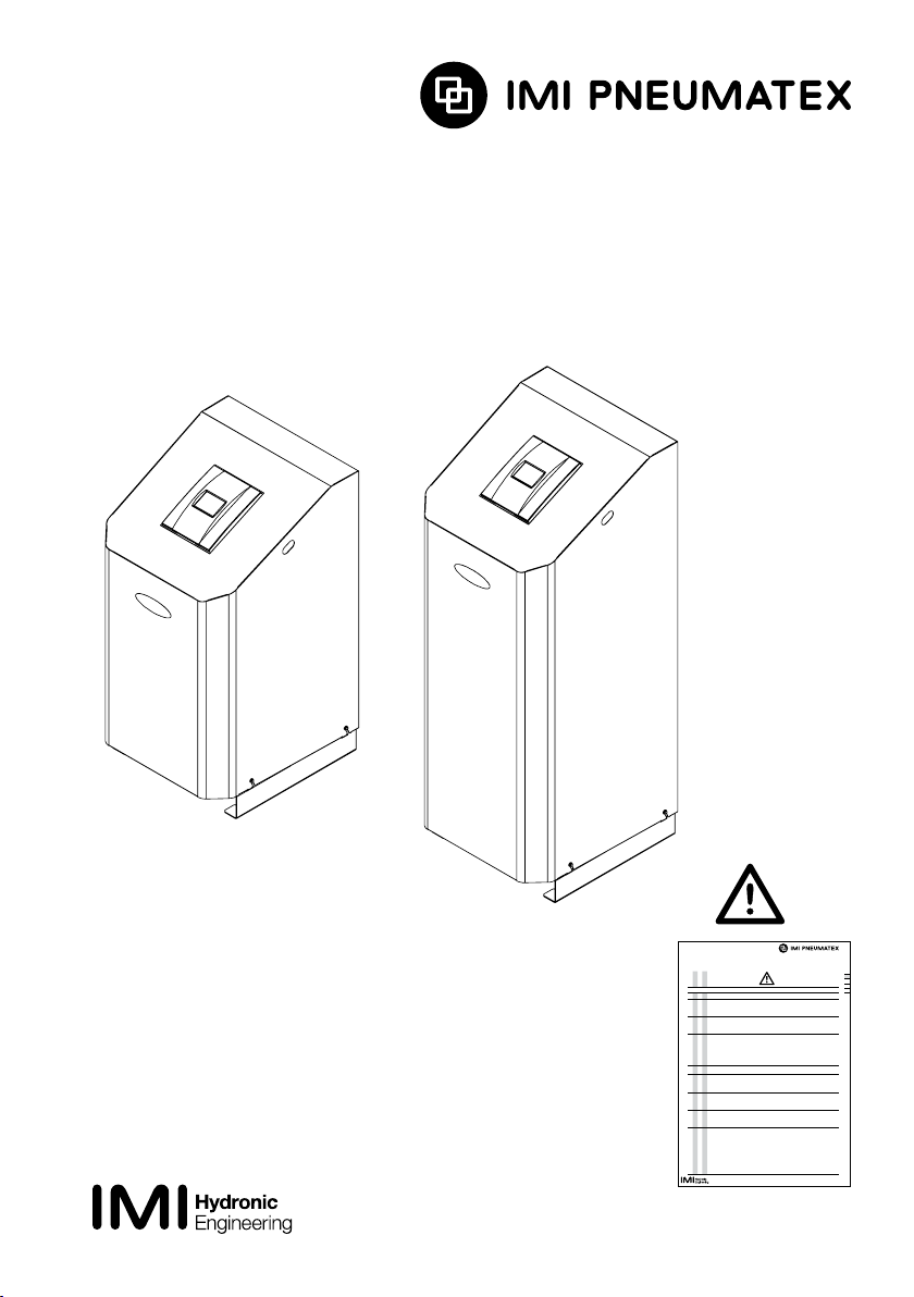
Compresso
Transfero
Vento
Pleno
Rell
SAFETY – INSPECTION
•••••Personnel
Installing and operating personnel must possess the appropriate knowledge and training.
•••••Follow the instructions
Installation, operation, maintenance and disassembly must be carried out as stated and showed in the dierent instruction
manualsmaking integral part of the delivery and in accordance with best practice. In addition to the IMI Hydronic Engineering
instructions, additional instructions from other companies may be included for the components used (e.g. backow preventers)
.
Youmust follow these instructions in the same way as the IMI Hydronic Engineering instructions.
Ifanything is unclear, please contact IMI Hydronic Engineering customer service.
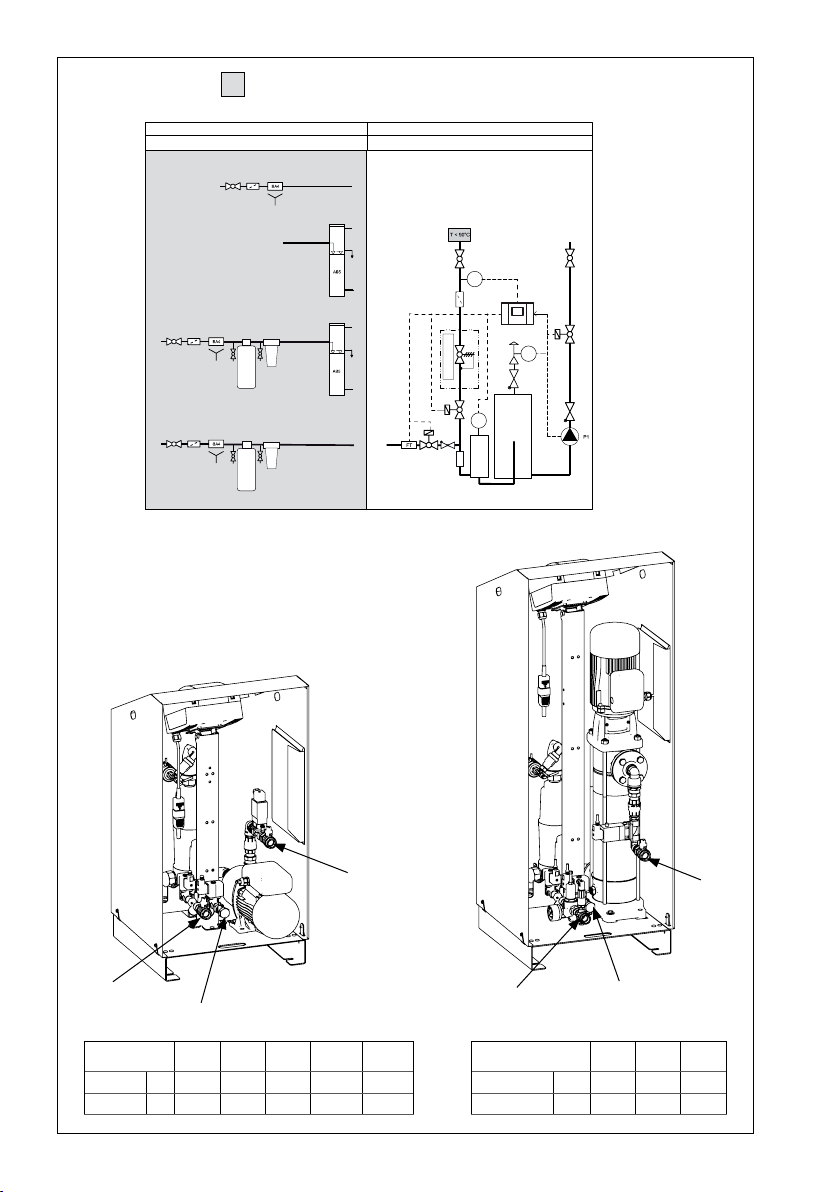
•••••Testsfor commissioning and periodic inspections
Testrequired for commissioning and periodic inspections must be performed according to the regulations in the country
where the device is installed and operated. There are no unied international regulations for the acceptance test prior to
commissioning and periodic inspections. It is usually the vessels that determine how the installation is classied.
These are CE type-tested in accordance with guideline PED/2014/68/EU for pressurised equipments. Forperiodic
inspections, openings are provided for ange-type or endoscope inspections.
•In Switzerland, Compresso does not require autorisation from the SVTI if the installation is protected in such a way that
psCH is not exceeded. Vesselswith psv x V up to 3000 bar*litres do not require inspection by the SVTI.
Following combinations withTecBox are recommended:
Primary vessel (2) TecBoxsafety valve (SV)
C 10 C15
≤ 1000 litres 3 bar on request
≤ 800 litres 3.75 bar on request
≤ 700 litres 4.2 bar on request
≤ 600 litres 5 bar on request
≤ 500 litres 6 bar 6 bar
≤ 300 litres – 10 bar
•ForTransfero as many extension vessels as required can be connected to the primary vessel. The CE-approved 2 bar
safety valve protects the vessels from inadmissible pressures. In Switzerland, SVTI inspection is not required for these
types of vessels.
•Backow preventer BA: Perform inspection and maintenance in accordance with EN 1717 and the rules in the operator’s
country. Functional testing, with documentation, must normally be carried out annually. Dirt trap (SF): Inspect and clean if
necessary after a drop in the water make-up capacity or before functional testing of the backow preventer BA. We recommend
including the Pleno P / P R / P CR / BA4R in the maintenance cycle of the connected pressure-maintaining or degassing station.
Follow the maintenance instructions for Rell softening modules. The Pleno P / P R / P CR / BA4R can work as an accessory in
systems requiring technical inspections (Compresso | Transfero) and can be included as part of the inspection.
•••••Place of installation
The access to the place of installation must be restricted to trained and specialised personnel. The oor statics must be able
to support the maximum operating and installation conditions. Connections for electricity,communication, main water and
waste water must correspond to the requirements of the device.The room must be thouroughly ventilated. Do not store
ammable, explosive materials near the pressure vessel. Pressurized containers (eg Compresso expansion vessels) must
be protected against external re, at least according to national regulations.
•••••Waterquality
IMI Hydronic Engineering devices are designed to maintain pressure, to degass or to make-up and/or treat water in closed
heating, solar and cooling systems with water that contains no aggressive or toxic agents.The entire system must be
dimensioned and operated in such a way as to minimise the amount of oxygen admitted through the make-up water or
through permeable components. Water treatment systems are to be dimensioned, installed and operated according to the
current state of the art.
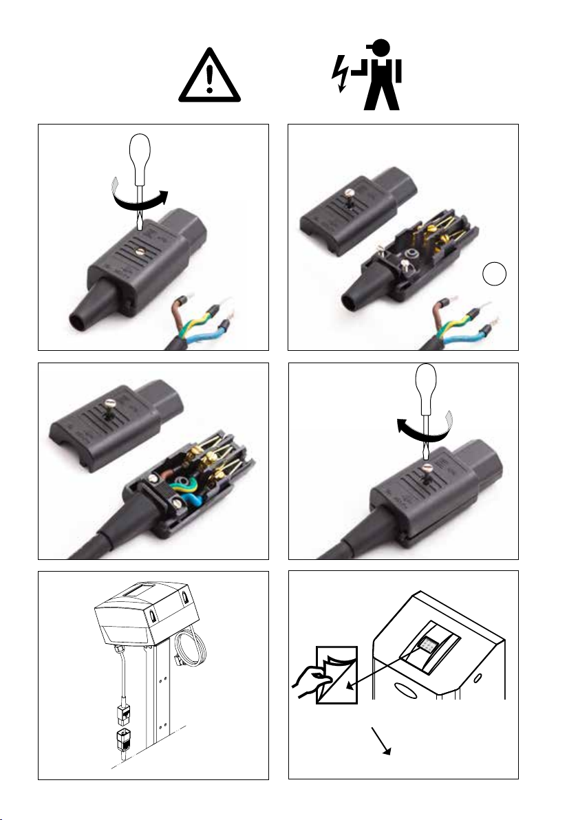
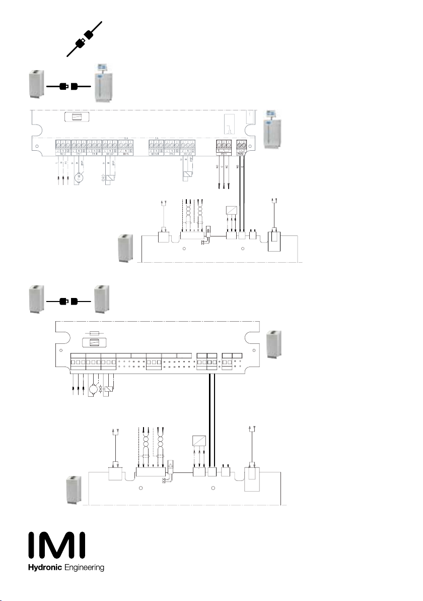
•••• Electrical connection
The electrical and the communication wiring and connections should be carried out by a qualied electrician, in accordance
with current local regulations.The devices and the potential free outputs must be disconnected from the electrical supply
before working on electrical components.
Protection on the supply to be done by the contractor:
Compresso C2.1, C10.1; C10.2; C15; CX: 10 A
Compresso C15.2: 16 A
Transfero range 4, 6, 8, 10, 14 = 1 x 230 V: T.1: 10 A
T.2: 16 A
Transfero 19, 25 = 3 x 400 V: 10 A
Vento range 2, 4, 6, 8, 10, 14 = 1 x 230V: 10 A
Vento range 19, 25 = 3 x 400 V: 10 A
Pleno PI9.1; PI6.1; PIX: 10 A
Pleno PI9.2; PI6.2: 16 A
Pleno P BA4R: not applicable
Residual current device (RCD) following local regulation.
If installed in residential building we recommend a commercially available line lter to the junction box.
07.2019
fr
WVMOIN0005
10.2019
Vento Connect
V 4 - 14
INSTALL
www.imi-hydronic.com