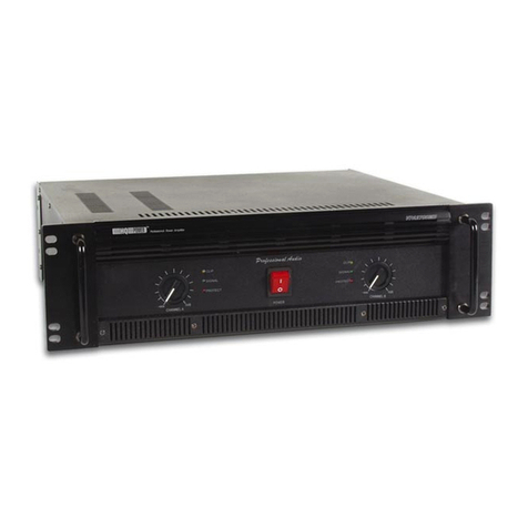
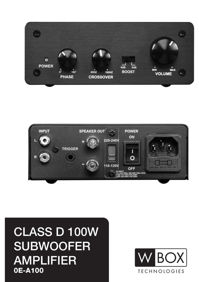
Impact Acoustics HC 75.2 User manual

Owner manual
HC Series ampliers
HC 75.2 - HC 150.2 - HC 250.2 - HC 550.2

2
INTRODUCTION
Congratulation on your purchase of a new Impact
High Current amplier.
We, at Impact, are aware of the fact that your
choice of an HC series amp has been deeply
thought out and that your expectations are high;
be sure that this product will fulll them all.
This HC amp is a sum of technology and good
sense that join sound reproduction quality with
the extraordinary capability to drive 1 Ohm
stereo as well as 2 Ohm mono loads.
This amp’s performances are unequalled and can
match any installation needs.
IMPORTANT
Impact HC ampliers are advanced units, pro-
vided with a sophisticated control system that
guarantees superior performances.
HC ampliers will give you a life of uncompro-
mised musical service under the strict condition
of a perfect installation; this requires car audio
installation knowledge and technique as well as
proper installation tools and equipment.
For this reason, we highly recommend you to ap-
ply to professional Impact Authorized Installers to
be sure of the absolute guarantee in terms of best
performances and safe installation.
If you decide to install your HC amplier by
yourself, we recommend you to read this owner’s
manual very carefully and to follow strictly all in-
structions inside.
INDEX
Introduction pag 2
Important pag 2
Warning pag 2
Main Features pag 3
Specications pag 3
Controls pag 4
Control Panel pag 4-5
Installation pag 6
Wiring System Nr. 1 pag 7
Wiring System Nr. 2 pag 8-9
Wiring System Nr. 3 pag 10-11
Mach Impact HC ampliers
to Impact subwoofer pag 12-13
Troubleshooting pag 14
WARNING
Impact HC ampliers can reproduce high sound
pressure levels that can cause permanent dam-
ages to your hearing system by long exposures.
The human hearing system is so deceiving as it
gets used to high sound pressure levels very soon;
as a consequence, a high sound level, which is
perceived as «ordinary», can be really dangerous.
We want you to take care of your ears so, in order
to avoid any inconvenience, state a safe sound
level.
State it before your hearing get used to extreme
loud volumes, just acting as follows:
1. Start listening at the lowest volume
2. Increase slowly your volume level by steps till
the sound is clear and pleasant without distor-
tion.
3. Once you have stated the comfort volume lev-
el, take due notice of it and do not overcome
it.

3
SPECIFICATIONSMAIN FEATURES
• Stereo, Bridged and Tri-Mode System
application Compatible
• Full Mos-Fet Circuitry
• 1 Ohm Stable Stereo Operation
• 2 Ohm Stable Mono Operation
• Variable input level controls
• Built-in excludible Low Pass/High Pass
Crossover
• Switchable low pass crossover slope
• 24 dB/Oct Variable subsonic Filter
• Built-in adjustable Bass-Boost
• Bass boos remote control phone jack
• High Temperature Thermal Management
System Circuitry
• Overload Protection System
• Output Short Circuit Protection
• DC Offset Circuit Protection
• RCA Line Output
HC 75.2 HC 150.2 HC 250.2 HC 550.2
RMS Power @ 4 Ohm - 13,8 V
W2 x 75 2 x 150 2 x 250 2 x 500
RMS Power @ 2 Ohm - 13,8 V
W2 x 150 2 x 270 2 x 400 2 x 700
RMS Power @ 1 Ohm - 13,8 V
W2 x 225 2 x 325 2 x 500 2 x 900
Mono Bridged RMS Power @ 4 Ohm - 13,8 V
W1 x 300 1 x 540 1 x 800 1 x 1.400
Mono Bridged RMS Power @ 2 Ohm - 13,8 V
W1 x 450 1 x 650 1 x 1.000 1 x 1.800
Total Harmonic Distortion
%0,03 0,03 0,03 0,03
Input Sensitivity
V0,2 ÷ 9 0,2 ÷ 9 0,2 ÷ 9 0,2 ÷ 9
Input Impedance
Kohm 47 47 47 47
Frequency Response
Hz 10 ÷ 30.000 10 ÷ 30.000 10 ÷ 30.000 10 ÷ 30.000
Signal to Noise Ratio
dB > 95 > 95 > 95 > 95
Damping Factor
250 250 250 250
High Pass Crossover Range
Hz 10 ÷ 4.000 10 ÷ 4.000 10 ÷ 4.000 10 ÷ 4.000
Low Pass Crossover Range
Hz 40 ÷ 4.000 40 ÷ 4.000 40 ÷ 4.000 40 ÷ 4.000
Subsonic Filter Range (24 dB/Oct)
Hz 10 ÷ 150 10 ÷ 150 10 ÷ 150 10 ÷ 150
Bass Boost 45 Hz
dB 0 / +18 0 / +18 0 / +18 0 / +18
Bass Boost Remote Control Jack
Yes Yes Yes Yes
Line Output
Yes Yes Yes Yes
Dimensions (W x H x D)
mm 260x60x345 260x60x390 260x60x450 260x60x855

4
CONTROLS
The Impact HC ampliers feature an extremely
exible set of input and output controls
which permit the widest range of installation
opportunities. In order to ensure best
performance, any adjustment should be made
after the amplier is installed and all input,
speaker and power connections are completed.
CONTROL PANELS
1. RCA LINE INPUT JACKS
It allows left and right inputs to be
connected to the amplier using RCA plugs.
2. SUBSONIC FILTER FREQUENCY CONTROL
Adjust crossover frequency of the subsonic
lter only, from 10 Hz to 150 Hz.
3. LOW PASS FILTER FREQUENCY CONTROL
Adjust crossover frequency of the low pass
output only, from 40 Hz to 4.000 Hz.
4. STEREO/MONO SWITCH
When set in MONO mode, the low pass signal
is mono with a 24 dB/Oct crossover slope.
When set in STEREO mode, the low pass signal
is stereo with a 12 dB/Oct crossover slope.
5. AMPLIFIER X-OVER SELECT SWITCH
a. LOW position: crossover operates in low-
pass mode
b. FULL position: crossover off
c. HI position: crossover operates in high-pass
mode
6. HIGH PASS FILTER FREQUENCY CONTROL
Adjust the crossover frequency of the high pass
output only, from 10 Hz to 4.000 Hz.
7. INPUT LEVEL CONTROL
Provides input level adjustment from 200 mV
to 9 V.
8. BASS EQ CONTROL
Adjust the 45 Hz frequency output from + 0 to
+18 dB.
11
9
8
7
56
4
3
2
1
10
12

5
CONTROL PANELS
9. POWER LED (green)
Illumination of this led indicates that
the amplier is operating normally.
10. PROTECTION LED (red)
Illumination of this led indicates that a short
circuit exist somewhere in your system. The
amplier turns off.
11. RCA LINE OUTPUT JACKS
Line out signal is automatically set by the
position of the amplier crossover select switch
(5).
When amplier crossover switch is in LOW
position (i.e. 150 Hz), line output signal is
automatically set in HIGH PASS mode at 150
Hz.
When amplier crossover switch is in Full
position line output signal is Full Range
When amplier crossover switch is in HI position
(i.e. 200 Hz), line output signal is automatically
set in LOW PASS mode at 200 Hz
12. BASS BOOST REMOTE CONTROL PHONE
JACK
Connecting the optional remote controller
(HC-R2) to this plug, you can set the bass boost
while driving

INSTALLATION
Please read Installation Precaution before
installing your Impact HC amplier, and then
refer to the diagrams provided to connect
power, speaker and audio input connections
according to your own system design.
Installation Precaution
• For safety, disconnect the battery during
installation. Conrm that your head-unit
or other equipment is turned off while
connecting the input jacks and speaker
terminals.
• Select a location inside your vehicle which
has adequate ventilation and protected from
dust and moisture
• Before drill or cut any holes, investigate your
car’s layout very carefully. Take care when
you work near gas tank, hydraulic and fuel
lines, electrical wiring.
• Do not operate the amplier when un-
mounted. Fix all audio system components
securely within your car to prevent shorts
and damage especially in case of an
accident.
• Do not mount this amplier so that the wire
connections are unprotected or likely to be
damaged by nearby objects.
• If you need to replace a fuse, only replace it
with a fuse of exactly same type and rating.
• Use proper sized wires to prevent electrical
re, system damages and to obtain peak
performance.
Amplier Installation
• Bolt the amplier to the mounting surface.
Do not mount the amplier upside down, as
it will restrict airow over the heat sink.
• Using a 2 AWG, or larger, wire, run a ground
wire from the GND terminal of the amplier
to the nearest chassis ground. Make sure
that the connection to the chassis is rust free
and cleared of all paint.
• Run a wire (same gauge of ground wire)
from the positive terminal of the battery to
the + 12 V terminal of the amplier. Install
an in-line fuse holder at about 45 cm. (18”)
from the positive (+) terminal of the battery.
• If multiple ampliers are to be run, and
a distribution block is used, then run the
largest gauge wire from the battery (+)
to the location in the vehicle where the
distribution block is located. Install a fuse
holder (or a circuit breaker) at about 45 cm.
(18”) from the positive (+) terminal of the
battery. This fuse/circuit breaker must be
able to handle the total current of ampliers
being used. Now, individually fuse each
amplier after the distribution block at the
amplier location.
• Using a 12 AWG wire, run the Remote wire
from the REM terminal of the amplier to
the remote output of head-unit.
• Connect the RCA input terminals of the
amplier to the signal source using top
quality interconnect.
Set ampliers controls as described in the
system you choose and according to the
wiring diagrams that follow in this manual.
to output
of Head Unit

Connections:
• Power (+ 12 V, GND, REM) connections: refer
to the above diagram
• Input and speaker connections: as shown in
above diagram
WIRING SYSTEM Nr. 1
2 channel stereo conguration
Left Speaker Right Speaker
to Remote Control
from Head Unit
FUSE
to Battery
to output
of Head Unit
Settings:
• Adjust the Input Level control to suit the sig-
nal output from the source.
• For Full Range Speaker System set the selec-
tor AMPLIFIER X-OVER to the FULL position
• For Low Pass Speaker System (i.e. HC used as
a subwoofer amplier) set the selector AM-
PLIFIER X-OVER to the LOW position. Then
set the Low Pass Frequency control (LOW
PASS) to suit the speakers.
• For High Pass Speaker System (i.e. front sys-
tem, tweeter driving) set the selector AMPLI-
FIER X-OVER to the HI position. Then set the
High Pass Frequency control (HIGH PASS) to
suit the speakers.
• You can adjust the bass response setting the
BASS EQ control to an increase up to + 18
dB.
WARNING: an increase of 3 dB means the dou-
ble of power: use the BASS EQ control with care
and moderation since you may cause damages to
the subwoofer (not covered by warranty) .

8
WIRING SYSTEM Nr. 2
Simultaneous Stereo and Mono Conguration
to Remote Control
from Head Unit
FUSE
to Battery
to output
of Head Unit
Right Satellite Speaker
Left Satellite Speaker
Mono Speaker
High Pass Passive Crossover
Low Pass Passive Crossover

9
WARNING !
This wiring requires a minimum speaker
impedance of 2 Ohm or more (both front system
and subwoofer)
Connections:
• Connect a stereo signal source to amplier
inputs
• Connect the speakers as shown on the above
diagram. NOTE MINIMUM IMPEDANCES!!!
Settings
• Adjust the Input Level control to suit the
signal output from the source.
• Set the Crossover switch selector (AMPLIFIER
X-OVER) to the FULL position.
• You can adjust the bass response setting the
BASS EQ control to an increase up to + 18
dB.
WARNING: an increase of 3 dB means the double
of power: use the BASS EQ control with care and
moderation since you may cause damages to the
subwoofer (not covered by warranty).

10
WIRING SYSTEM Nr. 3
Two ampliers in a Bi-amp System
(front system + mono subwoofer)
AMP A - rear
AMP B - rear
AMP B - front
to output
of Head Unit
AMP A - front
Left Satellite
Speaker
Right Satellite
Speaker
to Remote Control
from Head Unit
FUSE
to Battery
to Remote Control
from Head Unit
FUSE
to Battery
Mono Speaker

11
Amplier A Input and Speaker Connections
• Connect the Input signal to amplier A as
shown in above diagram
• Connect the mono subwoofer as shown in
above diagram
Amplier A Settings
• Adjust the LEVEL control to suit the signal
output from the source.
• Set the Crossover switch selector
(AMPLIFIER X-OVER) to the LOW position.
Then set the Low Pass Frequency control
LOW PASS to suit the Subwoofer.
• Select the STEREO/MONO switch to MONO
-24 dB position.
• Set the SUBSONIC lter frequency to desired
position (we suggest a 20 to 40 Hz setting)
• You can adjust the bass response setting the
BASS EQ control.
WARNING: an increase of 3 dB means the
double of power: use the BASS EQ control
with care and moderation since you may cause
damages to the subwoofer (not covered by
warranty).
Amplier B Input and Speaker Connections
• Connect the LINE OUT of Amplier A to
the LINE INPUT of Amplier B. Be careful to
maintain polarity for correct imaging.
• Connect the front speakers to the speaker
connector terminals as shown on left of
above diagram.
Amplier B Settings
• Adjust the LEVEL control to suit the signal
output from the source.
• Set the Crossover switch selector
(AMPLIFIER X-OVER) to the FULL position.

12
Mach Impact HC ampliers to Impact subwoofer
Great power handling and High Current
capabilities make Impact HC ampliers the best
choice for powering a subwoofer system.
Here are some 2 Ohm subwoofer system mono
wiring conguration for the best performance.
Subwoofer 67 serie Subwoofer 57 serie

13
Subwoofer 37-47 serie Subwoofer 27 serie

14
TROUBLESHOOTING
Amplier will not power up
• Check fuse
• Check all power connections (+ 12 V, Ground
and Remote)
• Check for at least 3 V on remote wire
Amplier powers up, but then go into
Protection mode
All HC ampliers are equipped with a diagnostic
device that turns the amp off immediately in case
of
shorted speaker wire (or shorted speaker) or
faulty amplier.
To evaluate, disconnect all speaker wires and
re-power the amplier: if it doesn’t go into
protection mode the problem is in the speaker
or in the speaker wire. If the amplier goes into
protection mode with speaker leads disconnected,
the amplier is faulty.
The amplier can be restarted by turning the
remote power OFF and ON again.
Overheating
HC ampliers feature a built-in thermal control
device that turns them off in case of extreme
temperature conditions. If this case occurs, allow
the amplier to cool down before attempting to
restart it.
Thermal overload conditions are caused by a
lack of reasonable airow over the heat sink or
by driving speaker of lower impedance than
recommended.
No sound
• Check radio volume and fader control
• Check speaker wires for loose or disconnect
• Check RCA input cable for defective, loose or
disconnect
• Check speaker wires for loose or disconnect
Weak output
• Check head unit volume and fader control
• Check amplier level control setting
• Check that the correct crossover type has
been selected for the speaker being used
• Check RCA cables
• Check the head unit with another amplier in
good working condition.
Only one channel works
• Check the balance control on the head-unit
• Conrm that all terminal strip connections are
secure and tight
• Reverse the input RCA plugs at the amplier.
If the channel which is silent switches to the
other side the problem is either in the head-
unit or in the RCA interconnect
Hiss noise
• Check Input Level control of the amplier
• Check head unit and disconnect input RCA
cable. If the hiss disappears RCA cable or
head-unit are faulty
Alternator whine in speakers
• Conrm that the amplier and any other
signal sources are properly grounded.
• Remove RCA input from amplier. If the whine
disappear, check input cable and head-unit
This manual suits for next models
3
Table of contents
Other Impact Acoustics Amplifier manuals
Popular Amplifier manuals by other brands

PowerAcoustik
PowerAcoustik Razor RZ4-1200D manual
Phase Technologies
Phase Technologies A-BUS ABR-40 installation instructions
Phase Technologies
Phase Technologies P3-35 Install instructions
Gtec
Gtec g.USBamp Instructions for use

Triton Audio
Triton Audio Fethead Germanium user guide

Clear One
Clear One Converge PA 4160 datasheet
