Impact Subsea ISS360 User manual
IMPACT SUBSEA
INNOVATIVE UNDERWATER PRODUCTS www.impactsubsea.com
T. +44 (0) 1224 460 850
I
mpact Subsea Ltd, Company umber: SC498003, Registered in Scotland, Registered
Office: Unit 10, Castle Street, Castle Road Industrial Estate, Ellon, AB41 9FR, UK
E. info@impactsubsea.co.uk
W. www.impactsubsea.com
ISS360
Imaging Sonar
Installation & Ope ation Manual
Revision Number:
1.5
Date
24
th
Septembe 2020

IMPACT SUBSEA
INNOVATIVE UNDERWATER PRODUCTS www.impactsubsea.com
Document No: 0000.1991 | Version No: 1.5 | 24
th
Septembe 2020
2
Contents
1.0 Int oduction ................................................................................................................................................. 4
2.0 Specification ................................................................................................................................................ 5
2.1 Ove view ................................................................................................................................................. 5
2.2 Dimensions .............................................................................................................................................. 5
2.3 Acoustic, Heading & Attitude .................................................................................................................. 6
2.4 Communication, Powe & Physical .......................................................................................................... 6
3.0 Installation ................................................................................................................................................... 7
3.1 Elect ical Installation ............................................................................................................................... 7
3.1.1 Connecto Pin Out............................................................................................................................ 7
3.1.2 Powe ............................................................................................................................................... 8
3.1.3 Se ial Inte face ................................................................................................................................. 8
3.1.4 RS232 Wi ing .................................................................................................................................... 8
3.1.5 RS485 Wi ing .................................................................................................................................... 9
3.1.6 Ethe net Wi ing ................................................................................................................................ 9
3.1.7 Establishing Communications ........................................................................................................ 10
3.1.8 Connecto Mating .......................................................................................................................... 10
3.1.9 Connecto Cleaning ........................................................................................................................ 10
3.2 Installation Location .............................................................................................................................. 11
3.2.1 Acoustics (Image Pe fo mance) ..................................................................................................... 11
3.2.2 Alignment with Vehicle .................................................................................................................. 12
3.2.3 Magnetic Distu be s (Heading Pe fo mance) ................................................................................ 12
3.3 Mounting ............................................................................................................................................... 13
4.0 Ope ation ................................................................................................................................................... 14
4.1 Use with seaView Softwa e ................................................................................................................... 14
4.1.1 Initial Connection ........................................................................................................................... 15
4.1.2 ISS360 Sona Application ............................................................................................................... 16
4.1.3 ISS360 Ope ational Settings ........................................................................................................... 19
4.1.4 ISS360 Senso Settings ................................................................................................................... 21
4.1.6 Othe Settings & Logging ............................................................................................................... 24
4.1.7 Hot Keys ......................................................................................................................................... 25
5.0 Maintenance & Se vicing ........................................................................................................................... 26
6.0 Theo y of Ope ation .................................................................................................................................. 27
6.1 Sona – Basic P inciples ......................................................................................................................... 27
6.2 The Sona Equation ............................................................................................................................... 29
6.2.1 Sou ce Level (SL) ............................................................................................................................ 29
6.2.2 T ansmission Loss (TL) .................................................................................................................... 30

IMPACT SUBSEA
INNOVATIVE UNDERWATER PRODUCTS www.impactsubsea.com
Document No: 0000.1991 | Version No: 1.5 | 24
th
Septembe 2020
3
6.2.3 Noise Level (NL) ............................................................................................................................. 30
6.2.4 Di ectional Index (DI) ..................................................................................................................... 31
6.2.5 Detection Th eshold (DT) ............................................................................................................... 31
7.0 Wa anty .................................................................................................................................................... 32
8.0 Technical Suppo t ...................................................................................................................................... 33

IMPACT SUBSEA
INNOVATIVE UNDERWATER PRODUCTS www.impactsubsea.com
Document No: 0000.1991 | Version No: 1.5 | 24
th
Septembe 2020
4
1.0 Introduction
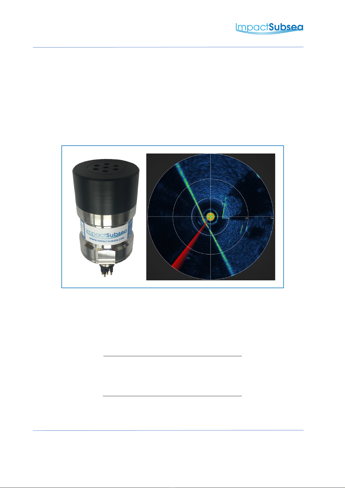
The ISS360 Imaging Sona p ovides excellent image cla ity with a ange capability of up to 90
mete s / 295 feet.
The ISS360 is a new gene ation of imaging sona , p oviding exceptionally fast scanning speeds
which we e p eviously unseen. This allows image y to be p oduced mo e quickly and is ideal fo
obstacle avoidance and navigation.
As a ve y compact imaging sona , the ISS360 is an ideal navigation and obstacle avoidance sona
fo the smallest to the la gest unde wate vehicles.
P ovided with a titanium housing the ISS360 is depth ated to 4,000 mete s / 13,123 feet.
Optionally, the ISS360 can be p ovided with an integ ated Attitude and Heading Refe ence System
(AHRS). This p ovides highly stable Heading, Pitch and Roll eadings.
The ISS360 imaging sona utilises a b oadband composite t ansduce coupled with CHIRP acoustics
to p ovide excellent image cla ity and ange capability.
The sona p ovides a full 360° field of vision p oduced by a mechanically scanned t ansduce . The
t ansduce utilises inductive coupling to the sona elect onics which enables ope ation without the
use of slip ings. This ensu es excellent longevity in ope ation.
All sona settings a e fully softwa e configu able using the seaView softwa e. The ISS360 sona
application within seaView is highly intuitive; ensu ing ange, esolution and othe settings can
quickly and easily be adjusted.
As an alte native to the seaView softwa e, a softwa e development kit is available fo thi d pa ty
integ ation and inte face development.
ISS360 Sonar (Titanium)

IMPACT SUBSEA
INNOVATIVE UNDERWATER PRODUCTS www.impactsubsea.com
Document No: 0000.1991 | Version No: 1.5 | 24
th
Septembe 2020
5
2.0 Specification
2.1 Overview
Above: ISS360 (Titanium)
2.2 Dimensions
The dimensions of the ISS360 sona a e shown below:
All dimensions are in mm.

IMPACT SUBSEA
INNOVATIVE UNDERWATER PRODUCTS www.impactsubsea.com
Document No: 0000.1991 | Version No: 1.5 | 24
th
Septembe 2020
6
2.3 Acoustic, Heading & Attitude
Acoustic Attitude
F equency 700kHz Cent e
650 to 750kHz Optimal Bandwidth
600 to 900kHz Bandwidth Available
Pitch Range ± 90°
Roll Range ± 180°
Range 0.15 to 90 mete s Accu acy 0.2°
Range Resolution 7.5mm
2.5mm achievable at lowe anges
Resolution 0.1°
Beam Angle 23° Ve tical
2.2° Ho izontal
Headin
Signalling CHIRP & Continuous Wave Accu acy ± 1°
Step Size 0.225°, 0.45°, 0.9°, 1.8°, 3.6° & 7.2° Resolution 0.1°
Scan Angle 360° Continuous o Secto Scan
2.4 Communication, Power & Physical
Communications & Power Physical
Digital RS232, RS485 & Ethe net Weight
(Ai /F esh
Wate )
0.38/0.3kg
Depth Rating 4,000m
P otocol 9600 to 115,200 baud Tempe atu e Ope ating: -10°C to 40°C
Sto age: -20°C to 60°C
Input Voltage 12 to 65V DC Connecto Subconn MCBH8M-SS
(othe options available)
Powe (Standby) 110mA @ 24V DC
Powe (Scanning)* 150mA @ 24V DC
* Based on maximum powe level and scanning speed

IMPACT SUBSEA
INNOVATIVE UNDERWATER PRODUCTS www.impactsubsea.com
Document No: 0000.1991 | Version No: 1.5 | 24
th
Septembe 2020
7
3.0 Installation
3.1 Electrical Installation
The ISS360 Sona is fitted with a SubConn MCBH8M-SS connecto as standa d. This will
mate to a SubConn MCIL8F connecto /cable assembly.
3.1.1 Connector Pin Out
The standa d connecto pinout is p ovided below:
Male Connector on ISS360 Sonar
Pin
Func
tion
Mating Wire Colour
1
0VDC
(Power)
Black
2
12
-
65
V
DC
White
Ethernet TX
-
Red
4
Ethernet TX+
Green
5
Ethernet RX
-
/ Serial 0V
Orange
6
Ethernet RX+ / Serial 0V
Blue
7
RS2 2 TX & RS485 A+
White/Black
8
RS2 2 RX & RS485 B
-
Red/Black
IMPACT SUBSEA
INNOVATIVE UNDERWATER PRODUCTS www.impactsubsea.com
Document No: 0000.1991 | Version No: 1.5 | 24
th
Septembe 2020
8
3.1.2 Power
The ISS360 Sona powe input is pola ity p otected and can accept a DC voltage f om 12 to
65V.
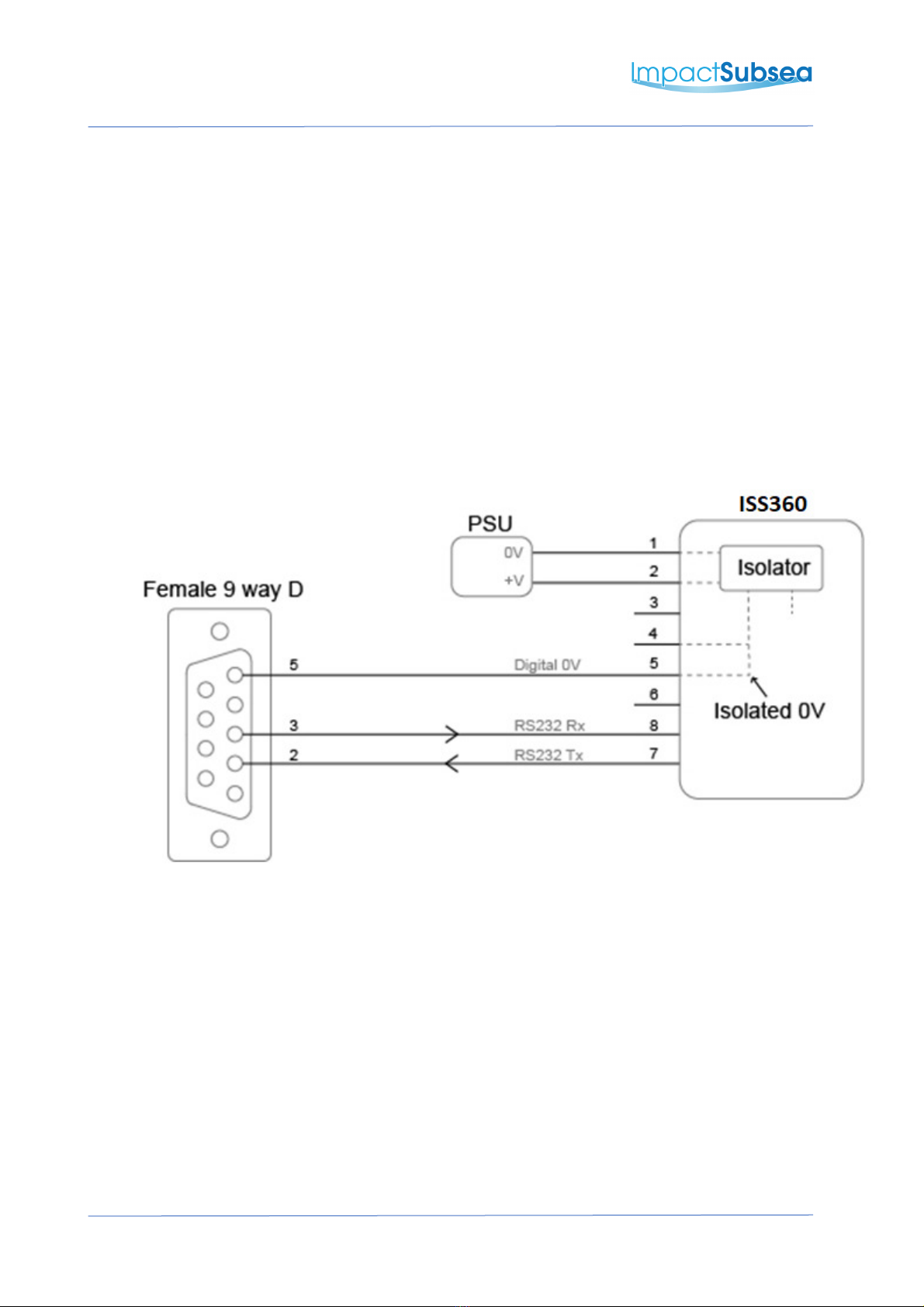
3.1.3 Serial Interface
Both the RS232 and RS485 inte faces a e isolated f om the supply and the sona has in-line
fused p otection on the se ial lines. A p olonged t ansient voltage on these lines will blow
the su face mount fuses which will equi e eplacement by Impact Subsea o an app oved
se vice agent.
3.1.4 RS232 Wiring
Note: RS232 will not function if the digital 0V pin is not used as the RS232 ground
IMPACT SUBSEA
INNOVATIVE UNDERWATER PRODUCTS www.impactsubsea.com
Document No: 0000.1991 | Version No: 1.5 | 24
th
Septembe 2020
9
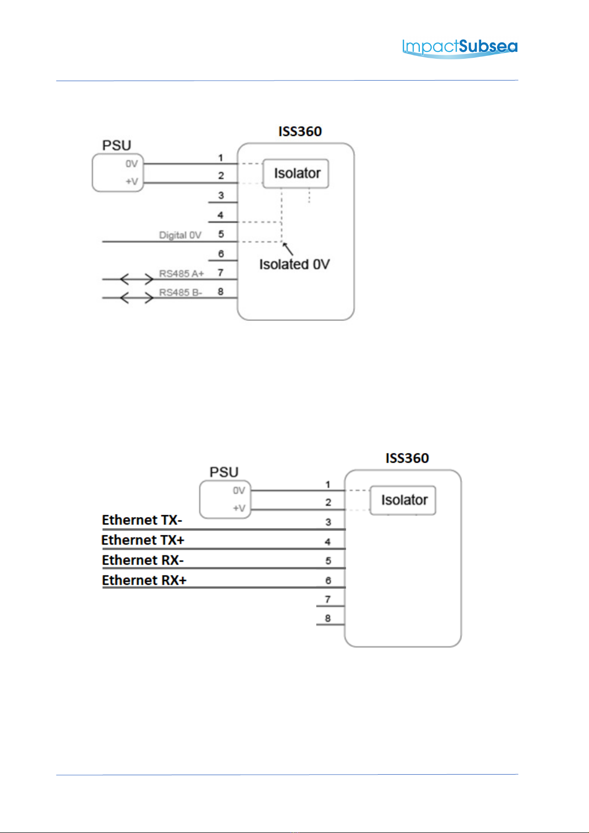
3.1.5 RS485 Wiring
The digital 0V must be connected on an RS485 inte face, othe wise the voltage potential
between one of the A+ o B- lines to g ound could each a damaging level.
3.1.6 Ethernet Wiring
IMPACT SUBSEA
INNOVATIVE UNDERWATER PRODUCTS www.impactsubsea.com
Document No: 0000.1991 | Version No: 1.5 | 24
th
Septembe 2020
10
3.1.7 Establishing Co unications
The default se ial settings a e RS232, 9600, N81.
If the ISS360 is tilted f om ve tical to upside down 3 times within the fi st 10 seconds of
powe up then it will tempo a ily configu e the se ial inte face to the default (RS232, 9600,
N81) and output an ASCII message displaying the settings.
Note: When the sona is powe cycled following this p ocess the se ial inte face setting will
eve t back to the last saved configu ation.
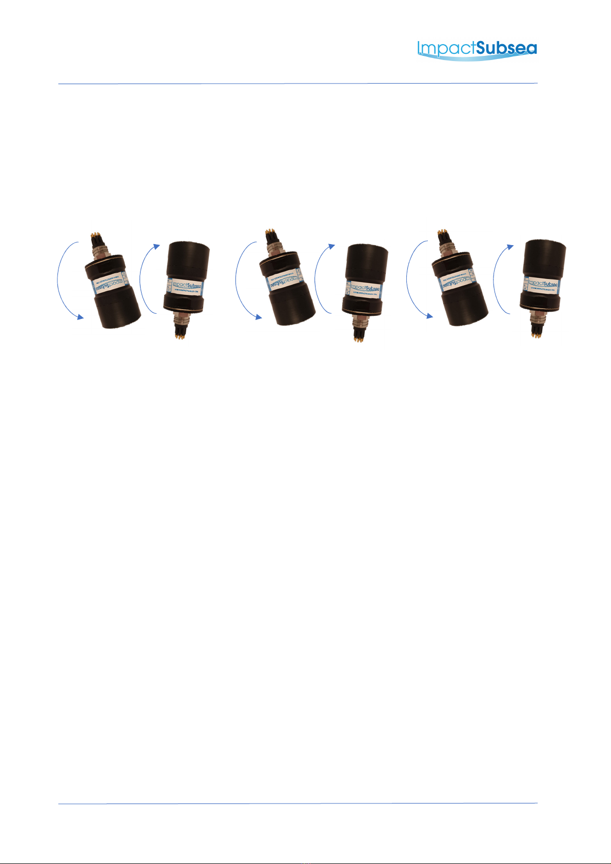
3.1.8 Connector Mating
When mating the cable to the SubConn connecto , to maximise the life of the connecto , it
is impo tant to obse ve the following:
•Always apply g ease befo e mating, Molykote 44 Medium g ease must be used.
•Disconnect by pulling st aight, not at an angle.
•Do not pull on the cable and avoid sha p bends at cable ent y.
•Do not ove -tighten the bulkhead nut.
Do not expose the connector to extended periods of heat or direct sunli ht. If a connector
becomes very dry, it should be soaked in fresh water before use.
3.1.9 Connector Cleaning
Gene al cleaning and emoval of any accumulated sand o mud on a connecto should be
pe fo med using sp ay based cleane (fo example Isop opyl Alcohol).
New g ease must be applied again p io to mating.

IMPACT SUBSEA
INNOVATIVE UNDERWATER PRODUCTS www.impactsubsea.com
Document No: 0000.1991 | Version No: 1.5 | 24
th
Septembe 2020
11
3.2 Installation Location
When evaluating the installation location of the ISS360 sona , the e a e seve al facto s to conside
to achieve optimum pe fo mance:
•Acoustics (Fo Imaging)
•Magnetic Distu be s (Fo Heading)
•Alignment with Vehicle (Fo Pitch/Roll)
3.2.1 Acoustics (Image Performance)
Of p ima y impo tance is the location of the sona to achieve good image y. The boot end
of the sona (see diagram in section 2 1) equi es to have a full 360° field of vision.
The boot end of the sona contains a single t ansduce mounted to a steppe moto . This
t ansduce otates th ough a 360° otation in o de to p ovide a 360° image of the sona ’s
su oundings.
When ope ating with a cent al f equency of 700kHz, the sona has a 23° ho izontal beam.
It is the efo e impo tant to ensu e that no pa t of the sona mount/vehicle passes within
this 23° beam. If it does, the pa t will be shown on the sona image and may educe ange
pe fo mance.
Ideally the ISS360 should not be ope ated in close p oximity to othe acoustic equipment
with the same ope ational f equency (650 to 750kHz). Othe acoustic equipment within
this f equency ange may cause acoustic i egula ities in the sona image.
If equi ed, the ISS360 ope ational f equency can be adjusted to move it out of band with
othe equipment.
IMPACT SUBSEA
INNOVATIVE UNDERWATER PRODUCTS www.impactsubsea.com
Document No: 0000.1991 | Version No: 1.5 | 24
th
Septembe 2020
12
3.2.2 Alignment with Vehicle
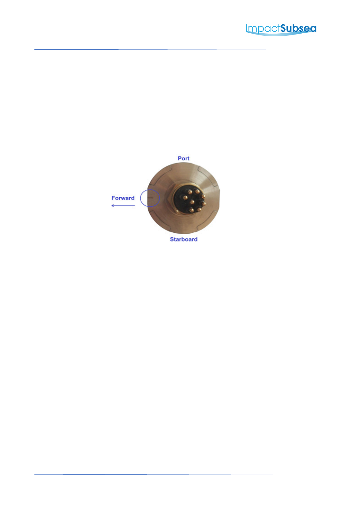
The standa d installation is to install the ISS360 sona with the boot end facing upwa ds,
connecto facing downwa ds.
The sona should be installed so that the top of the boot is pe fectly level.
The indentation on the connecto endcap should be installed pointing fo wa d, in the
di ection of the vehicle’s t avel:
The sona can also be installed with the connecto facing upwa ds and the boot end facing
downwa ds. In this installation o ientation, ensu e that the ‘Sonar is Inverted’ box is ticked
in the seaView ISS360 O ientation settings window. This will automatically co ect the
image y to compensate fo the inve ted sona installation.
3.2.3 Magnetic Disturbers (Heading Performance)
When the heading output is used, the ISS360 should be mounted as fa as possible f om
sou ces of magnetic inte fe ence.
Elect ical items which can cause magnetic inte fe ence include moto s, t ansfo me and
valve packs. Fe ous metals o any othe magnetically active mate ials will also have
influence on the heading eading.
Thus, whe e possible, the sona should be installed as fa away f om magnetically active
mate ials as is possible.

IMPACT SUBSEA
INNOVATIVE UNDERWATER PRODUCTS www.impactsubsea.com
Document No: 0000.1991 | Version No: 1.5 | 24
th
Septembe 2020
13
3.3 Mounting
The ISS360 should be mounted using clamps a ound the mid-section of the body. The body has a
20mm ecess to allow a clamp to be tightened secu ely a ound the unit.
When mounting the Acetal ve sion of the ISS360, ensu e excessive mounting fo ce is not used.
A non-metallic clamp should be used. In the event this is not possible, effo t should be made to
elect ically isolate the clamp f om the ISS360 housing.
This can be achieved by using ubbe o plastic st ips a ound the body of the ISS360.
The ISS360 has two flats on eithe side of the connecto endcap end of the body. These a e to
enable the unit to sit tightly against anothe flat su face if available. These flats also help p event
the sona moving when on the wo kbench fo testing.

IMPACT SUBSEA
INNOVATIVE UNDERWATER PRODUCTS www.impactsubsea.com
Document No: 0000.1991 | Version No: 1.5 | 24
th
Septembe 2020
14
4.0 Operation
4.1 Use with seaView Software
Shown above: seaView ISS360 Sonar Application
The ISS360 Sona is supplied with the intuitive Impact Subsea seaView softwa e on USB. The latest
ve sion of seaView can be downloaded f om www.impactsubsea.com
seaView softwa e wo ks with all of the Impact Subsea ange of unde wate senso s. Single senso s
can be ope ated o multiple senso s togethe .
The ISS360 sona will ope ate with seaView ve sion 2.0 o newe . seaView is designed fo use with
a PC unning the Windows 7, 8 o 10 ope ating system.
The ISS360 application within the seaView softwa e has been designed to be highly intuitive and
easy to use. Fo this eason, this manual only cove s the co e a eas of the softwa e to help the
use obtain familia ity with the application upon fi st use.

IMPACT SUBSEA
INNOVATIVE UNDERWATER PRODUCTS www.impactsubsea.com
Document No: 0000.1991 | Version No: 1.5 | 24
th
Septembe 2020
15
4.1.1 Initial Connection
Shown above: Initial seaView launch screen
To begin, ensu e the sona is connected to the compute via RS232, RS485 o Ethe net
communications and is powe ed on.
Upon launch of seaView, the softwa e will automatically scan the available communication
po ts to detect the imaging sona .
Once detected, the sona will be displayed in the ‘Devices’ section in the cent e of the
display. In the above example, the ISS360 sona with se ial numbe 1660.0015 has been
detected via an Ethe net connection and had an IP add ess of 192.168.1.200
Should a sona be connected afte unning the softwa e, the sea ch button should
be p essed to sea ch fo the newly connected sona .
Left click once on the sona then click on the ‘ISS360’ app at the left-hand side of the
sc een.
This will open the ISS360 sona application and the sona will automatically sta t to scan.
IMPACT SUBSEA
INNOVATIVE UNDERWATER PRODUCTS www.impactsubsea.com
Document No: 0000.1991 | Version No: 1.5 | 24
th
Septembe 2020
16
4.1.2 ISS360 Sonar Application
Shown above: ISS360 Application
P ovided in this section is an ove view of the key featu es of the application:
Colour Pallet:
To the left of the sc een is the colou pallet selecto , clicking on this will allow you to select
va ious colou pallet options fo the sona data to be ende ed in.
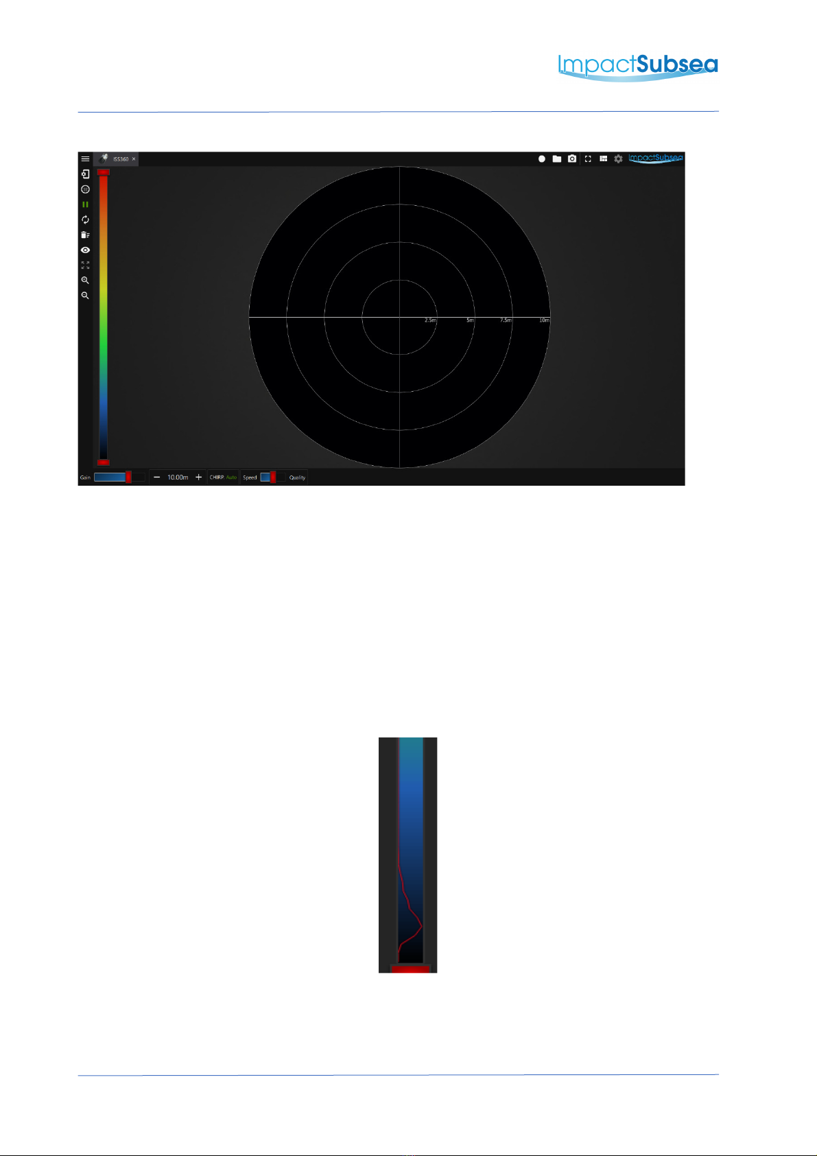
Raw Data:
The aw data etu ning f om the sona is p esented as a ed line ove laid onto the colou
pallet:
To ensu e all data is plotted on sc een, the colou pallet should cove all of the aw data
being shown.

IMPACT SUBSEA
INNOVATIVE UNDERWATER PRODUCTS www.impactsubsea.com
Document No: 0000.1991 | Version No: 1.5 | 24
th
Septembe 2020
17
Ima e Threshold & Contrast:
Using the ed handle on the uppe and lowe pa t of the colou pallet allows the data
th eshold and cont act to be adjusted.
This allows the sona image to be adjusted to suit the equi ements of the application at
hand:
•Weake ta gets can be emoved f om sc een by aising the lowest ed handle.
•Highe cont ast can be p ovided by lowe ing the uppe most ed handle.
Seve al examples of adjusting these va iables on the same image a e shown below:
Standa d setting – all data shown
Uppe Red Handle lowe ed - inc easing
cont ast
Lowe Red Handle aised – emoving
weake ta gets

IMPACT SUBSEA
INNOVATIVE UNDERWATER PRODUCTS www.impactsubsea.com
Document No: 0000.1991 | Version No: 1.5 | 24
th
Septembe 2020
18
Re ular Access Controls:
Along the lowe pa t of the sc een, the cont ols which equi e most egula access a e p ovided:
•Gain Slider
oThe amount of amplification of the aw signal can be adjusted he e
•Ran e
oThe distance the sona is to look ove can be adjusted
•CHIRP
oTu n CHIRP signalling On, Off o set to Auto based on ange input
•Speed/Quality Slider
oThe esolution and scanning speed of the sona can be set he e
oSpeed: Moving towa ds ‘Speed’ will enable a la ge step size and lowe bins. This
will inc ease the scan ate of the sona and educe the esolution – ideal fo
navigation & obstacle avoidance
oQuality: Moving towa ds ‘Quality’ will enable a smalle step size and highe bins.
This will inc ease the esolution of the sona image and dec ease the scan ate –
ideal fo ta get identification o su vey wo k

IMPACT SUBSEA
INNOVATIVE UNDERWATER PRODUCTS www.impactsubsea.com
Document No: 0000.1991 | Version No: 1.5 | 24
th
Septembe 2020
19
4.1.3 ISS360 Operational Settings
Shown above: ISS360 Setup
Clicking the Setup icon will allow access to the ope ational settings of the sona .
Shown above: ISS360 Setup
In this tab, featu es such as the scan angle of the sona (full 360 o use defined secto scan) can
be configu ed.
Flyback can be used to speed up secto scans. Instead to scanning ight to left then left to ight; in
this mode, the sona will p oduce image y one way then quickly flyback to the sta t position and
sta t again.

IMPACT SUBSEA
INNOVATIVE UNDERWATER PRODUCTS www.impactsubsea.com
Document No: 0000.1991 | Version No: 1.5 | 24
th
Septembe 2020
20
Note:
Bins a e the numbe of samples that the sona sends to the seaView softwa e fo each ‘Ping’ that
is makes.
When set to ‘Auto’ seaView will ead the numbe of pixels p esent on you display sc een and
equest the sona to send one sample pe pixel. This sends the maximum numbe of values which
can physically be shown on sc een at any one time.
If ope ating on a low baud ate se ial connection and also using a ve y high- esolution monito , you
may wish to disable the ‘Auto’ featu e and manually input a lowe numbe of bins. Alte natively,
ensu e that you move the Speed/Quality ba towa ds ‘Speed’ on the egula access cont ols (see
p evious page).
This will ensu e that the sona scans quickly and no latency is int oduced.
Elements of the sona display can be enabled o disabled (such as the heading, image smoothing
etc) by clicking the Display Options icon .
Shown above: ISS360 isplay Options
Table of contents
Other Impact Subsea Sonar manuals


Popular Sonar manuals by other brands

Furuno
Furuno FSV-35S Operator's manual

Simrad
Simrad Simrad SP70 Operator's manual

Eagle
Eagle FISHEASY ST - Installation and operation instructions

Sonavision
Sonavision 2392 mercury user manual

Lowrance
Lowrance X-55 Installation and operation instructions

Lowrance
Lowrance LCG-2400 Install and operation instructions


