Impact Subsea ISS360HD User manual
IMPACT SUBSEA
INNOVATIVE UNDERWATER PRODUCTS www.impactsubsea.com
T. +44 (0) 1224 460 850
Impact Subsea Ltd, Company Number: SC498003, Registered in Scotland, Registered
Office: Unit 10, Castle Street, Castle Road Industrial Estate, Ellon, AB41 9FR, UK
W. www.impactsubsea.com
ISS360 & ISS360HD
Imaging Sonar
Installation & Operation Manual
Revision Number:
2.1
Date
26th September 2022

IMPACT SUBSEA
INNOVATIVE UNDERWATER PRODUCTS www.impactsubsea.com
Document No: 0000.1991 | Version No: 2.1 | 26th September 2022 2
Contents
1.0 Introduction ...................................................................................................................................4
2.0 ISS360 Specification .......................................................................................................................5
2.1 Overview ....................................................................................................................................5
2.2 Dimensions.................................................................................................................................5
2.3 Acoustic & Attitude ....................................................................................................................6
2.4 Communication, Power & Physical ............................................................................................6
2.5 Acoustic Beam Pattern...............................................................................................................7
3.0 ISS360HD Specification ..................................................................................................................8
3.1 Overview ....................................................................................................................................8
3.2 Dimensions.................................................................................................................................8
3.3 Acoustic & Attitude ....................................................................................................................9
3.4 Communication, Power & Physical ............................................................................................9
3.5 Acoustic Beam Pattern.............................................................................................................10
4.0 Installation....................................................................................................................................10
4.1 Electrical Installation................................................................................................................10
4.1.1 Connector Pin Out.............................................................................................................11
4.1.2 Power ................................................................................................................................11
4.1.3 Serial Interface ..................................................................................................................12
4.1.4 RS232 Wiring.....................................................................................................................12
4.1.5 RS485 Wiring.....................................................................................................................13
4.1.6 Ethernet Wiring.................................................................................................................13
4.1.7 Establishing Communications ...........................................................................................14
4.1.8 Connector Mating .............................................................................................................14
4.1.9 Connector Cleaning...........................................................................................................15
4.2 Installation Location.................................................................................................................15
4.2.1 Acoustics (Image Performance) ........................................................................................15
4.2.2 Alignment with Vehicle .....................................................................................................16
4.3 Mounting..................................................................................................................................17
5.0 Operation .....................................................................................................................................18
5.1 Use with seaView Software......................................................................................................18
5.1.1 Initial Connection..............................................................................................................19
5.1.2 ISS360 Sonar Application ..................................................................................................20
5.1.3 ISS360 Operational Settings..............................................................................................23
5.1.4 ISS360 Sensor Settings ......................................................................................................25

IMPACT SUBSEA
INNOVATIVE UNDERWATER PRODUCTS www.impactsubsea.com
Document No: 0000.1991 | Version No: 2.1 | 26th September 2022 3
5.1.6 Other Settings & Logging ..................................................................................................28
5.1.7 Hot Keys ............................................................................................................................29
6.0 Maintenance & Servicing .............................................................................................................30
7.0 Theory of Operation.....................................................................................................................31
7.1 Sonar – Basic Principles............................................................................................................31
7.2 The Sonar Equation..................................................................................................................33
7.2.1 Source Level (SL) ...............................................................................................................33
7.2.2 Transmission Loss (TL).......................................................................................................34
7.2.3 Noise Level (NL).................................................................................................................34
7.2.4 Directional Index (DI) ........................................................................................................35
7.2.5 Detection Threshold (DT)..................................................................................................35
8.0 Warranty ......................................................................................................................................36
9.0 Technical Support.........................................................................................................................37
IMPACT SUBSEA
INNOVATIVE UNDERWATER PRODUCTS www.impactsubsea.com
Document No: 0000.1991 | Version No: 2.1 | 26th September 2022 4
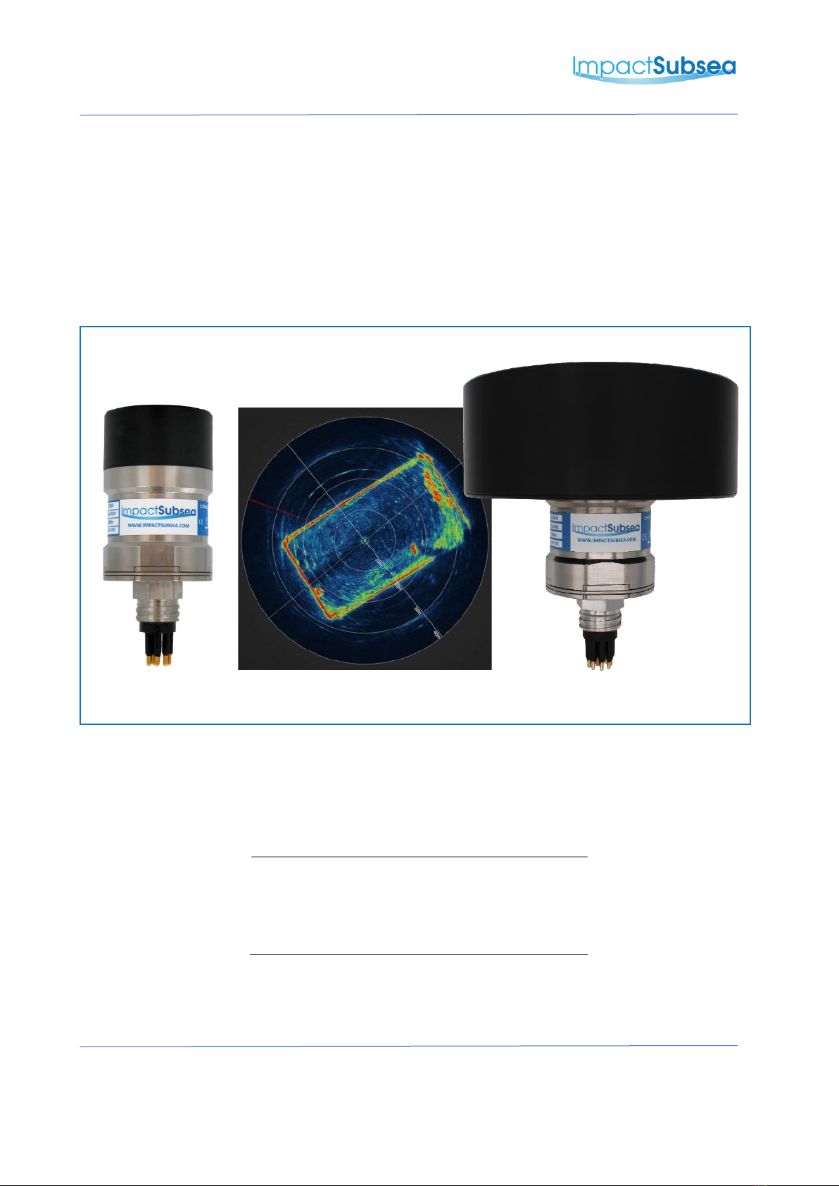
1.0 Introduction
The ISS360 family of imaging sonars provide excellent image clarity and range performance.
The ISS360 is a new generation of imaging sonar, providing exceptionally fast scanning capability.
As a very compact imaging sonar, the ISS360 is an ideal navigation and obstacle avoidance sonar
for the smallest to the largest underwater vehicles. The ISS360HD offers a further enhancement on
image quality and range capability.
Provided with a titanium housing the ISS360 is depth rated to 4,000 meters / 13,123 feet.
Optionally the sonar can also be provided depth rated to 6,000 meters / 19,685 feet. The
ISS360HD is rated to 6,000 meters / 19,685 feet as standard.
The ISS360 & ISS360HD can be provided with an integrated Attitude Reference System (ARS). This
provides highly stable Pitch and Roll readings.
Both ISS360 imaging sonars utilise a broadband composite transducer coupled with CHIRP
acoustics to provide excellent image clarity and range capability.
Each sonar provides a full 360° field of vision produced by a mechanically scanned transducer. The
transducer utilises inductive coupling to the sonar electronics which enables operation without the
use of slip rings. This ensures excellent longevity in operation.
All sonar settings are fully software configurable using the seaView software. The ISS360 sonar
application within seaView is highly intuitive; ensuring range, resolution and other settings can
quickly and easily be adjusted by the user.
As an alternative to the seaView software, a software development kit is available for third party
integration and interface development.
ISS360 ISS360HD
IMPACT SUBSEA
INNOVATIVE UNDERWATER PRODUCTS www.impactsubsea.com
Document No: 0000.1991 | Version No: 2.1 | 26th September 2022 5
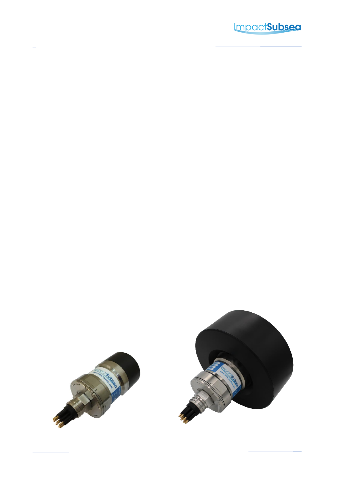
2.0 ISS360 Specification
2.1 Overview
Above: ISS360 Sonar
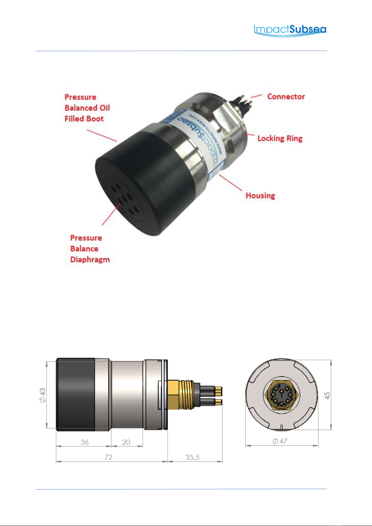
2.2 Dimensions
The dimensions of the ISS360 sonar are shown below:
All dimensions are in mm.

IMPACT SUBSEA
INNOVATIVE UNDERWATER PRODUCTS www.impactsubsea.com
Document No: 0000.1991 | Version No: 2.1 | 26th September 2022 6
2.3 Acoustic & Attitude
Acoustic
Attitude
Frequency
700kHz Centre
650 to 750kHz Optimal Bandwidth
600 to 900kHz Bandwidth Available
Pitch Range
± 90°
Roll Range
± 180°
Range
0.15 to 90 meters (4,000m depth rated unit)
0.15 to 80 meters (6,000m depth rated unit)
Accuracy
0.2°
Range
Resolution
7.5mm
2.5mm achievable at lower ranges
Resolution
0.1°
Beam Angle
23° Vertical
2.2° Horizontal
Signalling
CHIRP & Continuous Wave
Step Size
0.225°, 0.45°, 0.9°, 1.8°, 3.6° & 7.2°
Scan Angle
360° Continuous or Sector Scan
2.4 Communication, Power & Physical
Communications & Power
Physical
Digital
RS232, RS485 & Ethernet
Weight
(Air/Fresh
Water)
0.38/0.3kg (4,000m Rated)
0.37/0.3kg (6,000m Rated)
Depth Rating
4,000m or 6,000m
Protocol
9600 to 115,200 baud
Temperature
Operating: -10°C to 40°C
Storage: -20°C to 60°C
Input Voltage
12 to 65V DC
Connector
Subconn MCBH8M-SS
(other options available)
Power (Standby)
110mA @ 24V DC
Power (Scanning)*
150mA @ 24V DC
* Based on maximum power level and scanning speed
IMPACT SUBSEA
INNOVATIVE UNDERWATER PRODUCTS www.impactsubsea.com
Document No: 0000.1991 | Version No: 2.1 | 26th September 2022 7
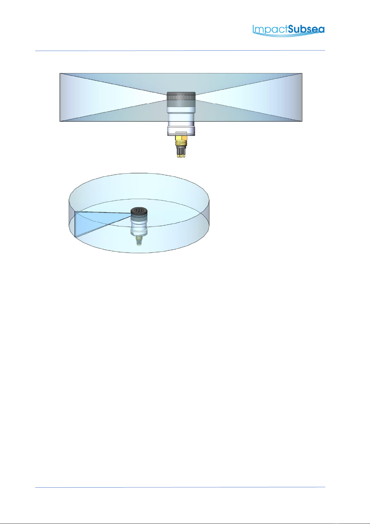
2.5 Acoustic Beam Pattern
The ISS360 sonar produces an acoustic fan beam which has been configured to provide
optimal coverage for the purposes of ROV navigation, obstacle avoidance and identification.

IMPACT SUBSEA
INNOVATIVE UNDERWATER PRODUCTS www.impactsubsea.com
Document No: 0000.1991 | Version No: 2.1 | 26th September 2022 8
3.0 ISS360HD Specification
3.1 Overview
Above: ISS360HD Sonar
3.2 Dimensions
The dimensions of the ISS360HD sonar are shown below:
All dimensions are in mm.

IMPACT SUBSEA
INNOVATIVE UNDERWATER PRODUCTS www.impactsubsea.com
Document No: 0000.1991 | Version No: 2.1 | 26th September 2022 9
3.3 Acoustic & Attitude
Acoustic
Attitude
Frequency
750kHz Centre
600 to 900kHz Bandwidth Available
Pitch Range
± 90°
Roll Range
± 180°
Range
0.45 to 100 meters
Accuracy
0.2°
Range
Resolution
2.5mm (300kHz CHIRP)
Resolution
0.1°
Beam Angle at
700kHz
30° Vertical
1° Horizontal
Signalling
CHIRP & Continuous Wave
Step Size
0.225°, 0.45°, 0.9°, 1.8°, 3.6° & 7.2°
Scan Angle
360° Continuous or Sector Scan
3.4 Communication, Power & Physical
Communications & Power
Physical
Digital
RS232, RS485 & Ethernet
Weight
(Air/Fresh
Water)
0.76/0.24kg
Depth Rating
6,000m
Protocol
9600 to 115,200 baud
Temperature
Operating: -10°C to 40°C
Storage: -20°C to 60°C
Input Voltage
12 to 65V DC
Connector
Subconn MCBH8M-SS
(other options available)
Power (Standby)
110mA @ 24V DC
Power (Scanning)*
150mA @ 24V DC
* Based on maximum power level and scanning speed
IMPACT SUBSEA
INNOVATIVE UNDERWATER PRODUCTS www.impactsubsea.com
Document No: 0000.1991 | Version No: 2.1 | 26th September 2022 10
3.5 Acoustic Beam Pattern
The ISS360HD sonar produces an acoustic fan beam which has been configured to provide
optimal coverage for the purposes of ROV navigation, obstacle avoidance and target
identification. The ISS360HD has a narrow horizontal beam (1°) by a wide vertical
beamwidth (30°). This beam pattern allows more of the vertical area to be captured. This is
ideal for close range target identification.
4.0 Installation
4.1 Electrical Installation
The ISS360 & ISS360HD Sonars are fitted with a SubConn MCBH8M-SS connector as
standard. This will mate to a SubConn MCIL8F connector/cable assembly and use a MCDLS
locking collar. Other connector options are available upon request.
IMPACT SUBSEA
INNOVATIVE UNDERWATER PRODUCTS www.impactsubsea.com
Document No: 0000.1991 | Version No: 2.1 | 26th September 2022 11
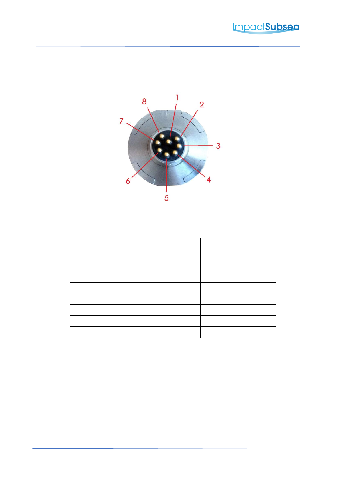
4.1.1 Connector Pin Out
The standard connector pinout is provided below:
Male Connector on ISS360 & ISS360HD Sonar
Pin
Function
Mating Wire Colour
1
0VDC (Power)
Black
2
12-65V DC
White
3
Ethernet TX-
Red
4
Ethernet TX+
Green
5
Ethernet RX- / Serial 0V
Orange
6
Ethernet RX+ / Serial 0V
Blue
7
RS232 TX & RS485 A+
White/Black
8
RS232 RX & RS485 B-
Red/Black
4.1.2 Power
The ISS360 & ISS360HD Sonar power input is polarity protected and can accept a DC
voltage from 12 to 65V. Do not attempt to power the ISS360 with an input voltage out with
this range.
When powering, the sonar should not be operated out of water for long periods of time.
Basic checks of operation can be performed out of water, but the unit should be submerged
once these are completed.
IMPACT SUBSEA
INNOVATIVE UNDERWATER PRODUCTS www.impactsubsea.com
Document No: 0000.1991 | Version No: 2.1 | 26th September 2022 12
4.1.3 Serial Interface
The ISS360 & ISS360HD sonars have in-line fuse protection on the serial lines. A prolonged
transient voltage on these lines will blow the surface mount fuses which will require
replacement by Impact Subsea or an approved service agent.
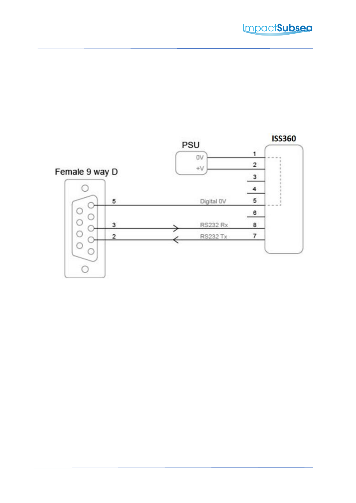
4.1.4 RS232 Wiring
Note: RS232 will not function if the digital 0V pin is not used as the RS232 ground
IMPACT SUBSEA
INNOVATIVE UNDERWATER PRODUCTS www.impactsubsea.com
Document No: 0000.1991 | Version No: 2.1 | 26th September 2022 13
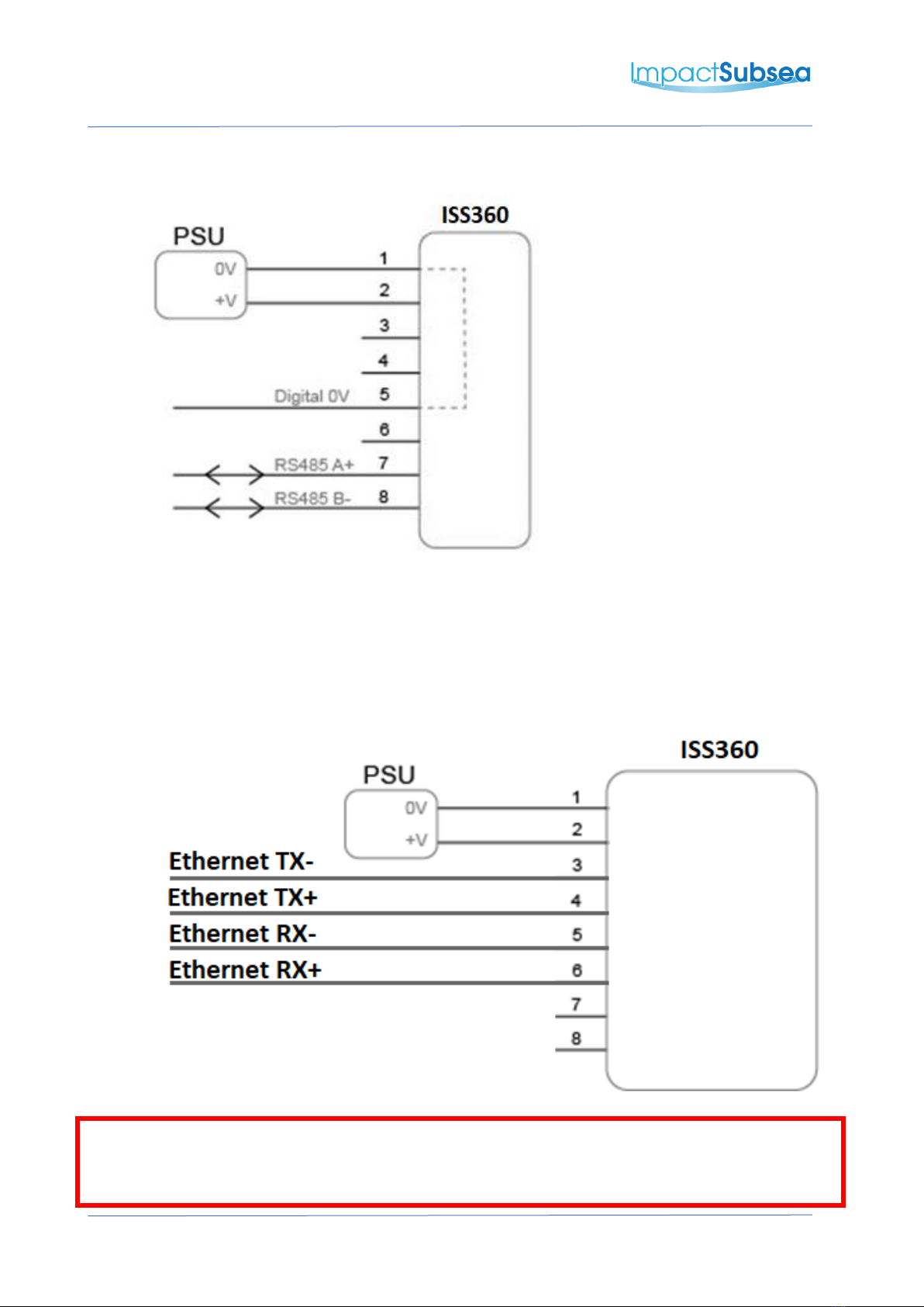
4.1.5 RS485 Wiring
The digital 0V must be connected on an RS485 interface, otherwise the voltage potential
between one of the A+ or B- lines to ground could reach a damaging level.
4.1.6 Ethernet Wiring
Note:
The ISS360 & ISS360HD cannot be powered over an ethernet connection. Any attempt to use a
power over ethernet connection will result in permanent damage to the ISS360/ISS360HD.

IMPACT SUBSEA
INNOVATIVE UNDERWATER PRODUCTS www.impactsubsea.com
Document No: 0000.1991 | Version No: 2.1 | 26th September 2022 14
4.1.7 Establishing Communications
The default dispatch serial settings are RS232, 115,200, N81.
If the sonar is tilted from vertical to upside down at least 3 times within the first 10 seconds
of power up then it will temporarily configure the serial interface to RS232, 9600, N81 and
output an ASCII message displaying the settings.
If running firmware version 3.0 and above, inverting 6 times within the first 20 seconds of
power up then it will temporarily configure the serial interface to RS485, 9600, N81 and
output an ASCII message displaying the settings.
Note: When the sonar is power cycled following this process the serial interface setting will
revert back to the last saved configuration.
4.1.8 Connector Mating
When mating the cable to the SubConn connector, to maximise the life of the connector, it
is important to observe the following:
•Always apply grease before mating, Molykote 44 Medium grease must be used.
•Disconnect by pulling straight, not at an angle.
•Do not pull on the cable and avoid sharp bends at cable entry.
•Do not over-tighten the bulkhead nut.
Do not expose the connector to extended periods of heat or direct sunlight. If a connector
becomes very dry, it should be soaked in fresh water before use.

IMPACT SUBSEA
INNOVATIVE UNDERWATER PRODUCTS www.impactsubsea.com
Document No: 0000.1991 | Version No: 2.1 | 26th September 2022 15
4.1.9 Connector Cleaning
General cleaning and removal of any accumulated sand or mud on a connector should be
performed using spray based cleaner (for example Isopropyl Alcohol).
New grease must be applied again prior to mating.
4.2 Installation Location
When evaluating the installation location of the sonar, there are several factors to consider to
achieve optimum performance:
•Acoustics (For Imaging)
•Alignment with Vehicle (For Pitch/Roll)
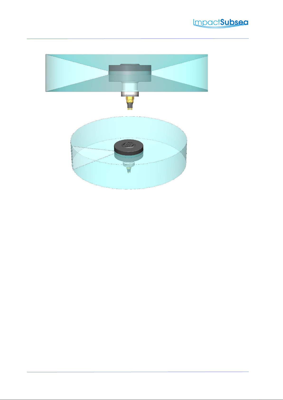
4.2.1 Acoustics (Image Performance)
Of primary importance is the location of the sonar to achieve good imagery. The boot end
of the sonar (see diagram in section 2.1 for the ISS360 and 3.1 for the ISS360HD) requires
to have a full 360° field of vision.
The boot end of the sonar contains a single transducer mounted to a stepper motor. This
transducer rotates through a 360° rotation in order to provide a 360° image of the sonar’s
surroundings.
When operating with a central frequency of 700kHz, the ISS360 has a 23° horizontal beam
(or 30° if using the ISS360HD). It is therefore important to ensure that no part of the sonar
mount/vehicle passes within this 23° or 30° beam. If it does, the part will be shown on the
sonar image and may reduce range performance.
Ideally the ISS360 should not be operated in close proximity to other acoustic equipment
with the same operational frequency (650 to 750kHz). Other acoustic equipment within
this frequency range may cause acoustic irregularities in the sonar image.
If required, the ISS360 operational frequency can be adjusted to move it out of band with
other equipment.

IMPACT SUBSEA
INNOVATIVE UNDERWATER PRODUCTS www.impactsubsea.com
Document No: 0000.1991 | Version No: 2.1 | 26th September 2022 16
4.2.2 Alignment with Vehicle
The standard installation is to install the ISS360 sonar with the boot end facing upwards,
connector facing downwards.
The sonar should be installed so that the top of the boot is perfectly level.
The indentation on the connector endcap should be installed pointing forward, in the
direction of the vehicle’s travel:
The sonar can also be installed with the connector facing upwards and the boot end facing
downwards. In this installation orientation, ensure that the ‘Sonar is Inverted’ box is ticked
in the seaView ISS360 Orientation settings window. This will automatically correct the
imagery to compensate for the inverted sonar installation.
IMPACT SUBSEA
INNOVATIVE UNDERWATER PRODUCTS www.impactsubsea.com
Document No: 0000.1991 | Version No: 2.1 | 26th September 2022 17
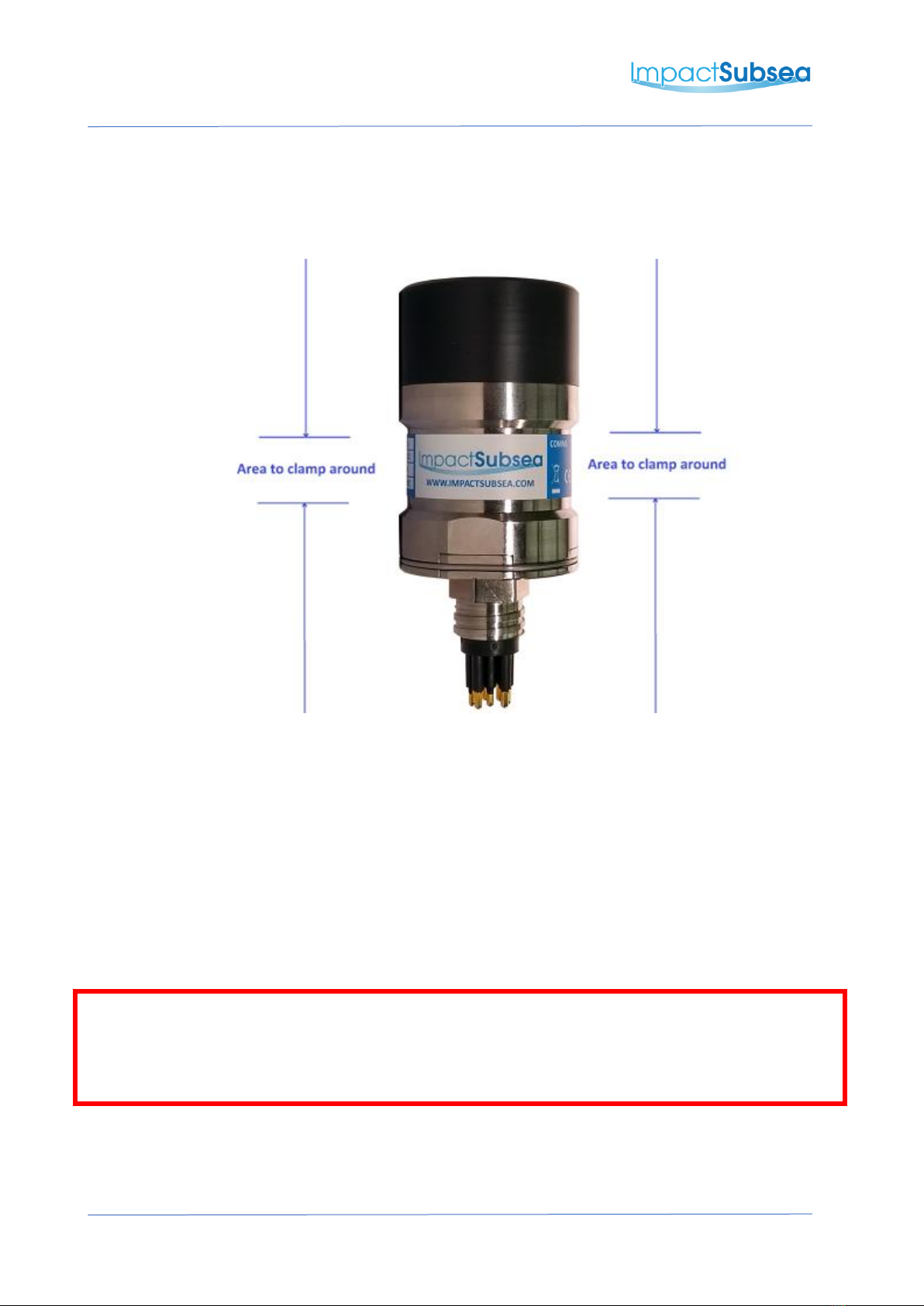
4.3 Mounting
The sonar should be mounted using clamps around the mid-section of the body. The body has a
20mm recess to allow a clamp to be tightened securely around the unit.
A non-metallic clamp should be used. In the event this is not possible, effort should be made to
electrically isolate the clamp from the sonar housing.
This can be achieved by using rubber or plastic strips around the body of the sonar.
The sonar has two flats on either side of the connector endcap end of the body. These are to
enable the unit to sit tightly against another flat surface if available. These flats also help prevent
the sonar moving when on the workbench for testing.
Note:
Sonar Boot: The black boot end of the sonar is oil filled under vacuum to remove all air. DO NOT
unscrew the boot from the sonar as the oil will escape and the sonar will require to be refilled with
oil.

IMPACT SUBSEA
INNOVATIVE UNDERWATER PRODUCTS www.impactsubsea.com
Document No: 0000.1991 | Version No: 2.1 | 26th September 2022 18
5.0 Operation
5.1 Use with seaView Software
Shown above: seaView ISS360 Sonar Application
The sonar is supplied with the intuitive Impact Subsea seaView software on USB. The latest
version of seaView can be downloaded from www.impactsubsea.com
seaView software works with all of the Impact Subsea range of underwater sensors. Single sensors
can be operated or multiple sensors together.
For sonars with version 2.0 firmware, seaView version 2.0 will be required. For sonars with version
3.0 firmware, seaView 3.0 or newer will be required. seaView is designed for use with a PC running
the Windows 7, 8 or 10 operating system. 32 and 64 bit versions of seaView are available.
The ISS360 application within the seaView software has been designed to be highly intuitive and
easy to use. For this reason, this manual only covers the core areas of the software to help the
user obtain familiarity with the application upon first use.

IMPACT SUBSEA
INNOVATIVE UNDERWATER PRODUCTS www.impactsubsea.com
Document No: 0000.1991 | Version No: 2.1 | 26th September 2022 19
5.1.1 Initial Connection
Shown above: Initial seaView launch screen
To begin, ensure the sonar is connected to the computer via RS232, RS485 or Ethernet
communications and is powered on.
Upon launch of seaView, the software will automatically scan the available communication
ports to detect the imaging sonar.
Once detected, the sonar will be displayed in the ‘Devices’ section in the centre of the
display. In the above example, the ISS360 sonar with serial number 1660.0015 has been
detected via an Ethernet connection and has an IP address of 192.168.1.200
Should a sonar be connected after running the software, the search button should
be pressed to search for the newly connected sonar.
Note:
Ethernet communications: If communicating via a network the ISS360 has DHCP enabled
by default, so it will automatically be allocated an IP address on the network.
If running directly into a PC - allocate the PC a static IP address to enable communication.
The default IP address of the ISS360 is 192.168.1.200. The PC should be configured to have
a compatible IP address (for example 192.168.1.100).
Left click once on the sonar then click on the ‘ISS360’ app at the left-hand side of the
screen. This will open the ISS360 sonar application and the sonar will automatically start to
scan. Both the ISS360 and ISS360HD make use of the same application.
IMPACT SUBSEA
INNOVATIVE UNDERWATER PRODUCTS www.impactsubsea.com
Document No: 0000.1991 | Version No: 2.1 | 26th September 2022 20
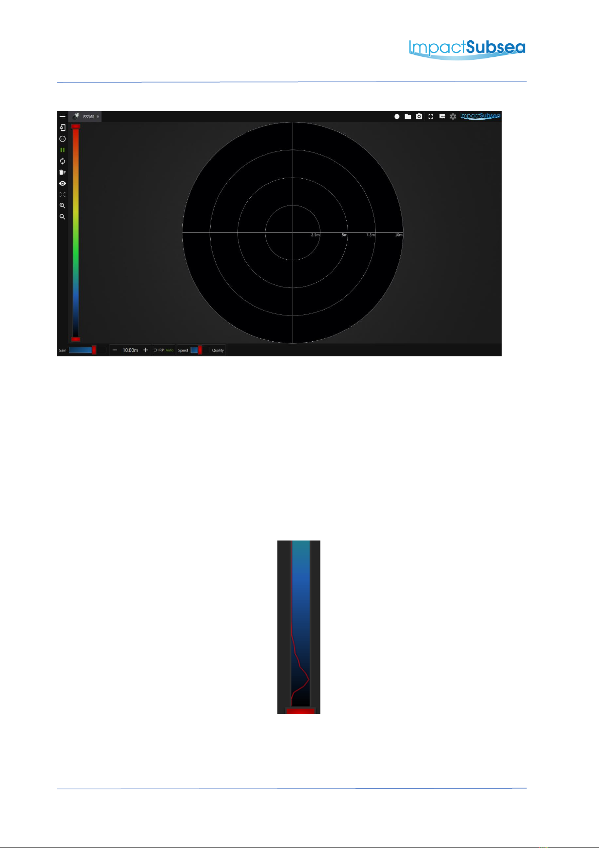
5.1.2 ISS360 Sonar Application
Shown above: ISS360 Application
Provided in this section is an overview of the key features of the application:
Colour Pallet:
To the left of the screen is the colour pallet selector, clicking on this will allow you to select
various colour pallet options for the sonar data to be rendered in.
Raw Data:
The raw data returning from the sonar is presented as a red line overlaid onto the colour
pallet:
To ensure all data is plotted on screen, the colour pallet should cover all of the raw data
being shown.
This manual suits for next models
2
Table of contents
Other Impact Subsea Sonar manuals


