Electrical Wiring
the protection circuit to engage.
The IMPACT LK Series amplifier was designed to operate effectively at loads down to 2 Ohms.
This means that you can install four 8 Ohm speakers per channel when using parallel wiring.
Increasing the number of woofers per channel at low frequencies (up to 100Hz) produces an
acoustic coupling effect. This acoustic coupling increases your power output by 3 dB per speaker.
When operating at 2 Ohms, the amplifier will increase their output power by approximately 50%. The
current draw will also increase by about the same amount, so be sure you have enough current to run the
amplifiers into a 2 Ohm load. If you lack adequate current, your music reproduction will be distorted.
Please note: The gain control of any car audio amplifier should not be mistaken for a volume control. It is
a sophisticated device, designed to match the output level of your audio source unit to the input level of
the amplifier. Do not adjust this input level to maximum unless your input level requires it. Ignoring these
instructions will result in an input overload to the amplifier, and excessive audio distortion. It can also cause
2 Ohm Operation (in stereo mode)
Wire the amplifier directly to the car battery. Make sure there is circuit protection (such as a fuse) on the
positive power lead, within 18 inches of the battery.
All IMPACT LK series power amplifiers are equipped with easy top access screw terminals. These
terminals are n in order to ensure excellent electrical contact and to resist corrosion.ickel-plated
When making electrical connections to the amplifier, please observe the following:
Use at least 8 gauge or heavier wire for power and ground connections.
For the ground connection, use the shortest possible wire to a good chassis ground point.
Wire the Remote connection to the remote turn-on lead of your equalizer or head unit. In some cases
this may be the power antenna lead of the head unit.
Fuses
Fus es prot ect bot h the ampl ifier and the electrical system of you r vehicle from faulty con dition s.
replace the fuse in you r ampl iifier, use a fuse of exactly the same type and rating. A different type or rating may
result in damage or cause a fire.
If you mus t
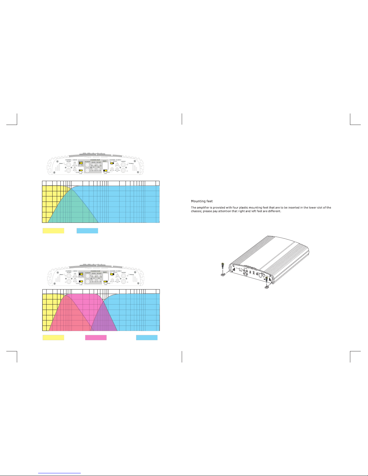
Mounting the Amplifier
Mark the location for the mounting screw holes by positioning the amplifier where you wish to install it and
use a scribe (or one of the mounting screws) inserted in each mounting hole to mark the mounting surface.
If the mounting surface is carpeted,measure the hole centers and mark with a felt tip pen.
Drill pilot holes in the mo unting surface for the mo unting screws and insert the mo unting
holes. Tighten them securely.
screws into these
Note: Before beginning your installation, be sure to take note of any wires, lines or other devices in your
vehicle which may be located behind any mounting surface.
-4- -5-
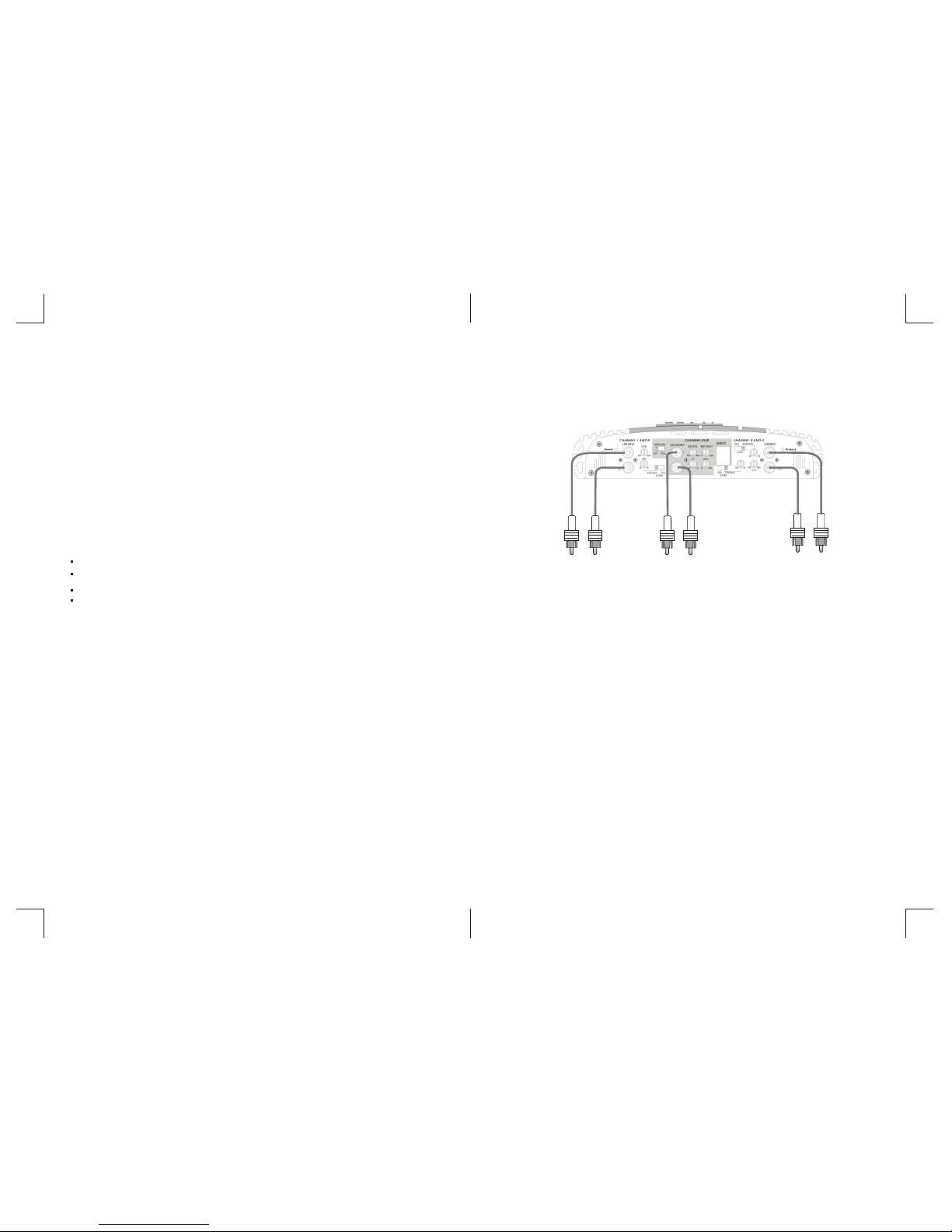
REAR
INPUTS
5 Channel Amplifier LK 705 - Input wiring
HEAD UNIT with Front/Rear/Sub OUTPUT
FRONT
INPUTS
SUB
INPUTS
If your HEAD UNIT have less than 3 RCA output, you can match the requested
INPUT plugs by using some “Y adapter ”